Weekly Task
Group assignment:
communicate between two boards.
Individual assignment:
design and build a wired &/or wireless network connecting at least two processors.
The assignment for this week is to design and build a wired or wireless that intergartes at least two Processors. I decided to do the serial bus communication using two nodes and a bus. One of my main reason for choosing the serial bus communication for this assignment is to try and understand how it work so that I can apply that know in my machine design project as I plan to in future build a cnc mill using the serial communication (Nodes).
Communication
Communication between two MCU is called embedded communication.To perform the communication one of the MCU act as a Sender and other to be as a receiver.MCU communications may in one direction or both, depends on the users choice.
Parallel Communication
Parallel interfaces transfer multiple bits at the same time. They usually require buses of data - transmitting across eight, sixteen, or more wires. Data is transferred in huge, crashing waves of 1’s and 0’s.It transmit multiple bits of data at same time.they require buses of data to transmitting across eight, sixteen, or more wires.
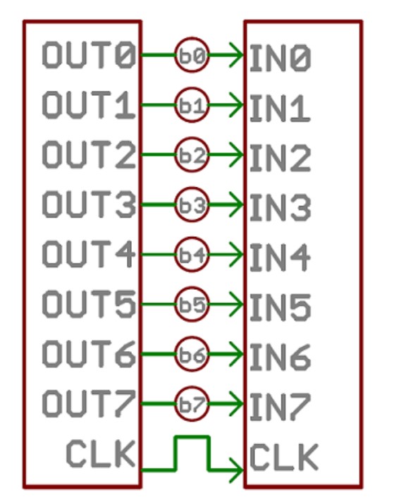
Paralle communication is fast and straightforward. If we go with this, we need to more I/O pins to establish this communication.. Details are taken from Link
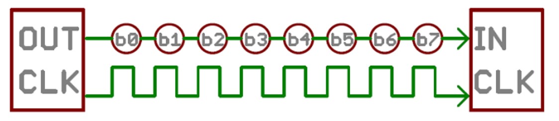
Serial Communication
Serial interfaces stream their data, one single bit at a time. These interfaces can operate on as little as one wire, usually never more than four. But this way of communication is slow, but its more reliable compare to Parallel. I refer Sparkfun website for knowing more about serial communication
There are various serial protocols for MCU to esstablish communication between other MCU.Serial Communication are sorted into two forms they are
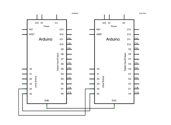
Master Writer/Slave Receiver(I2C Protocol)
The I2C protocol involves using two lines to send and receive data: a serial clock pin (SCL) that the Arduino or Genuino Master board pulses at a regular interval, and a serial data pin (SDA) over which data is sent between the two devices.
Group Assignment
Firstly I write I2C communication program using Wire.h library.
In the master we required Wire.h library.we begin the I2C bus using the Wire.begin() function. If no argument is provided in the function, Arduino will start as a master.
The code for master is given by:
#include <Wire.h>
void setup() {
Wire.begin();
Serial.begin(9600);
}
byte x = 0;
void loop() {
Wire.beginTransmission(8); // transmit to device #8
Wire.write("x received is "); // sends five bytes
Wire.write(x); // sends one byte
Serial.print("x sent is:");
Serial.println(x);
Wire.endTransmission(); // stop transmitting
x++;
delay(500);
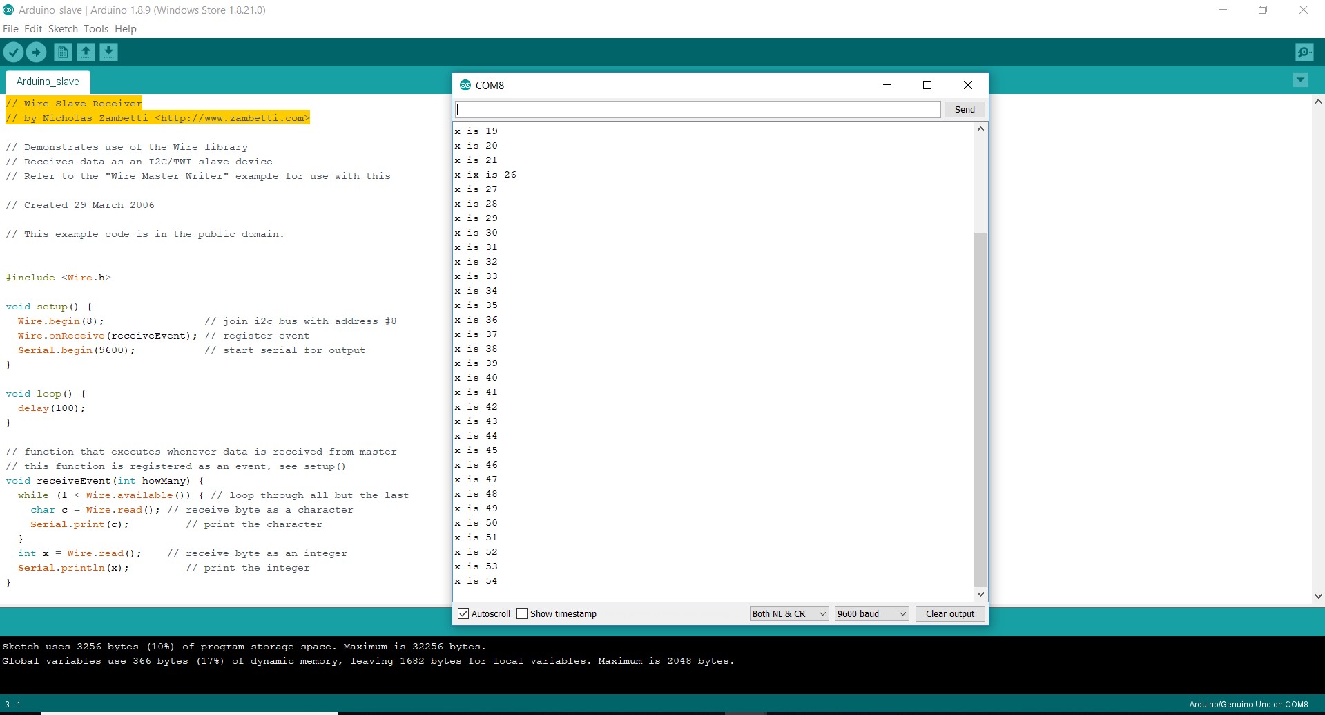
}the code for slave is given by
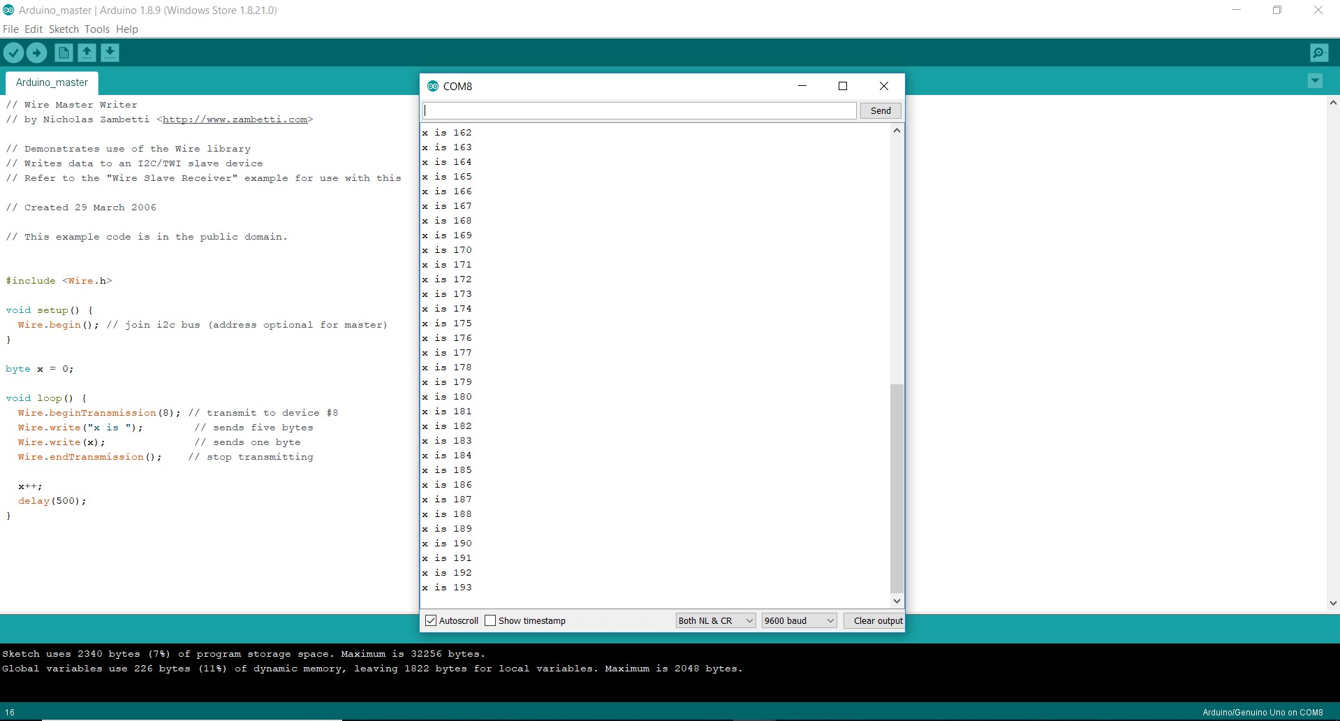
This is then outputted via serial
#include <Wire.h>


void setup() {

  Wire.begin(8);              // join i2c bus with address #8

  Wire.onReceive(receiveEvent); // register event

  Serial.begin(9600);           // start serial for output

}


void loop() {

  delay(100);

}


void receiveEvent(int howMany) {

  while (1 < Wire.available()) { // loop through all but the last

    char c = Wire.read(); // receive byte as a character

    Serial.print(c);         // print the character

  }

  int x = Wire.read();    // receive byte as an integer

  Serial.println(x);         // print the integer

}
Networking
Two or more computer systems linked together is known as networking. Local area network and wide area network are the types of networks.
Networking is simply an information exchange between you and another person. It involves establishing relationships with people. A network consists of two or more computers that are linked in order to share resources(such as printers and CD's), exchange files, or allow electronic communications. The computers on a network may be linked through cables, telephone lines, radio waves, satellites, or infrared light beams.
Individual Assignment
Designing - RS232 Serial Bus
In this Week I made two board i,e. master and slave (bridge and node)board.I followed Neil Board and re-route it.
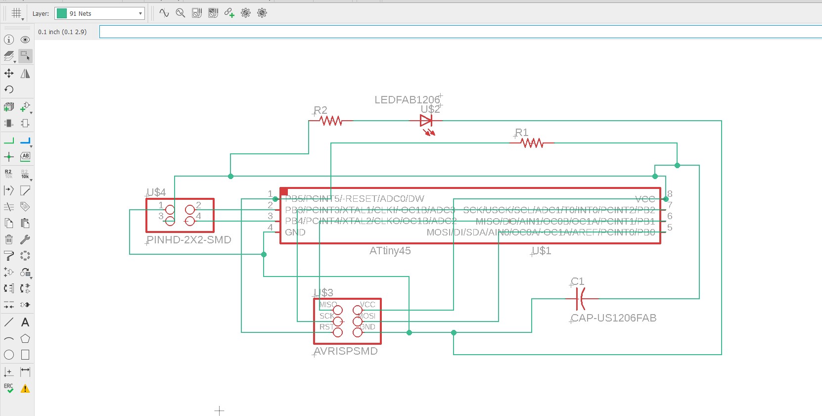
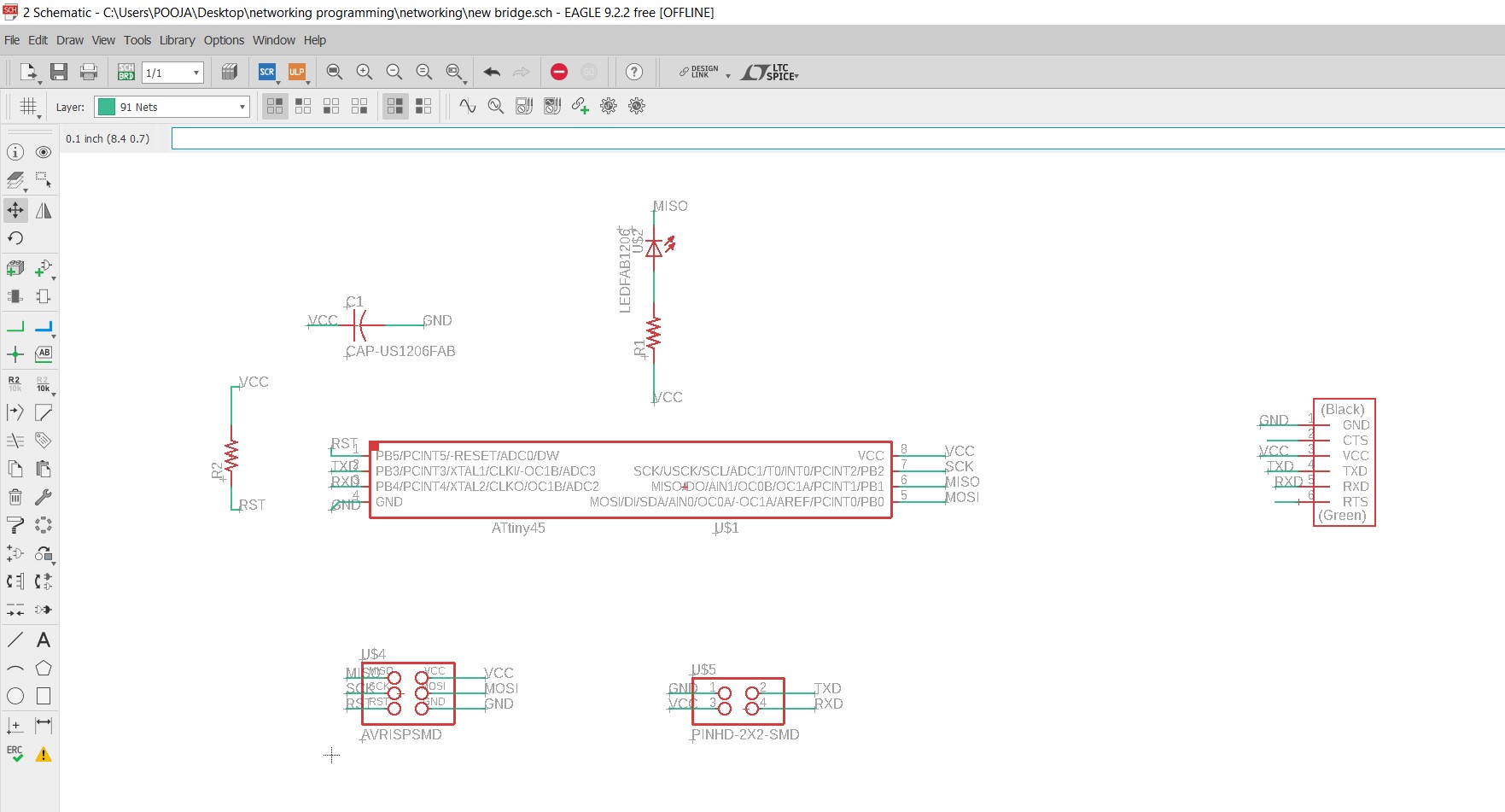
1.Node - This board connect to the bridge board to receive the signal or for communicate.
Schematic diagram of my node board
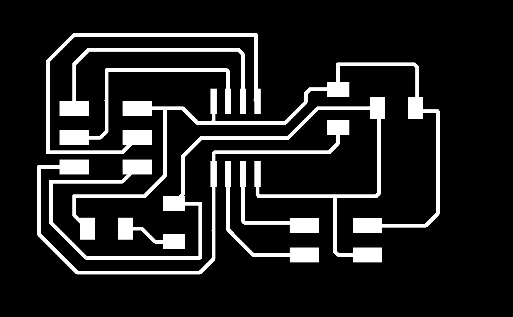
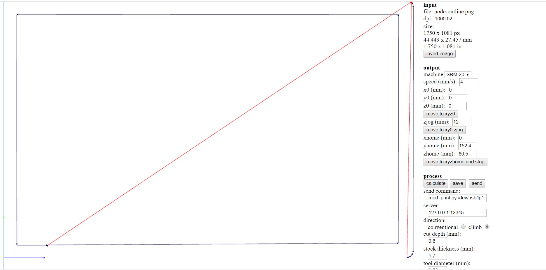
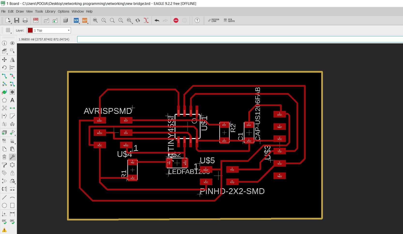
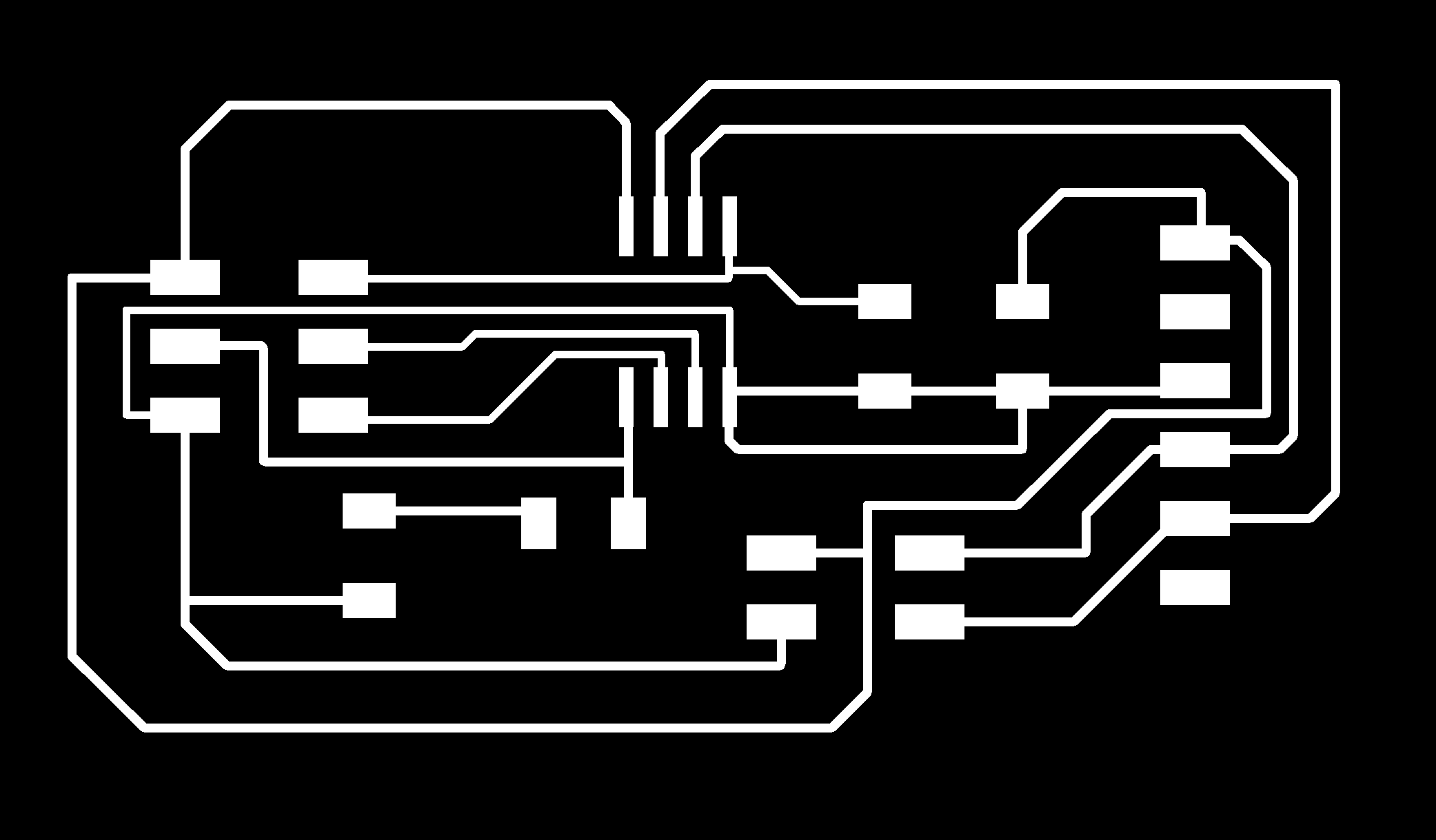
I routed board and make .Png file
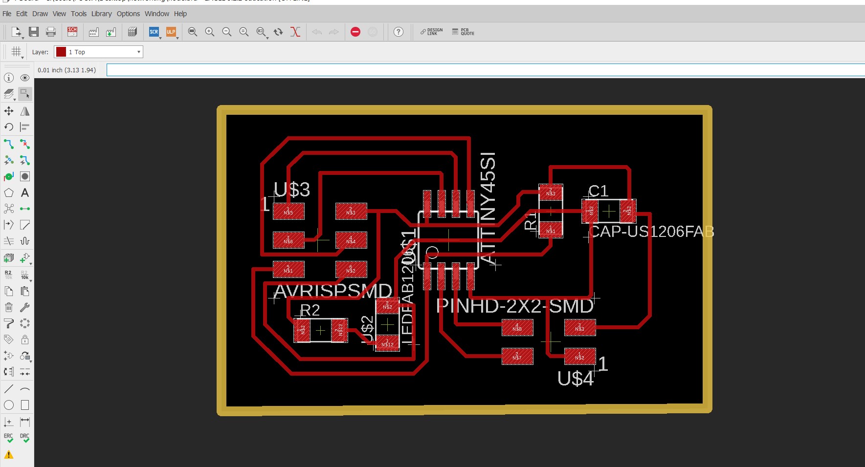
PNG file
|

|
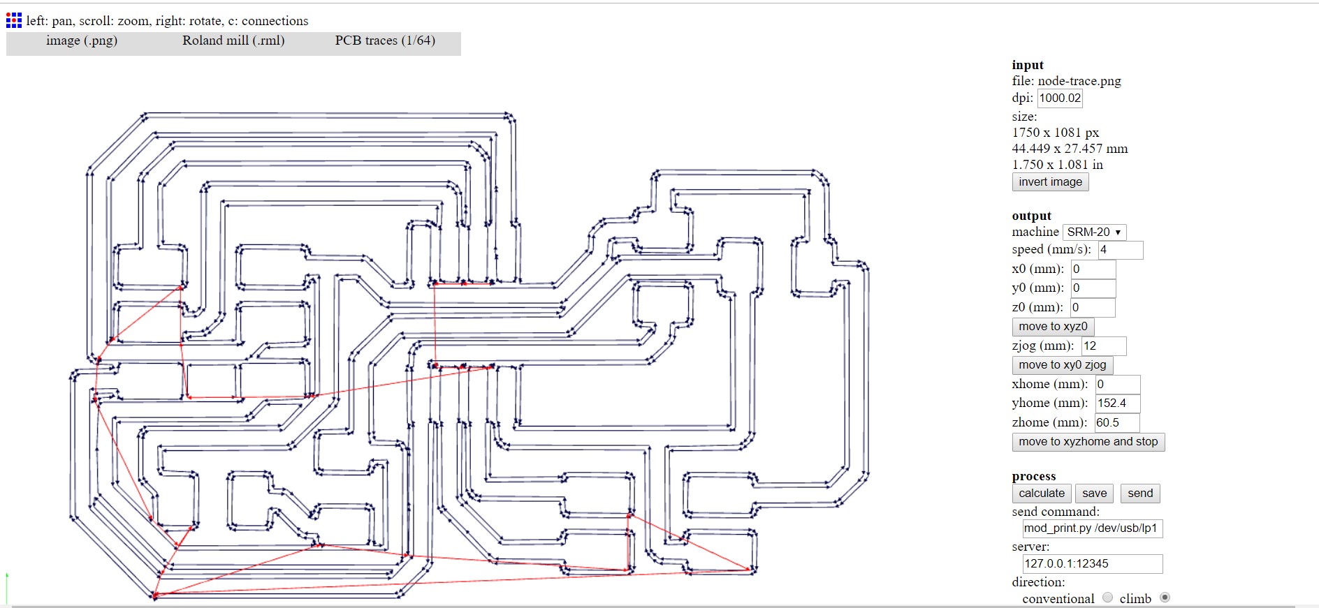
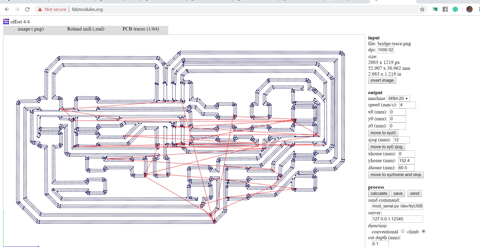
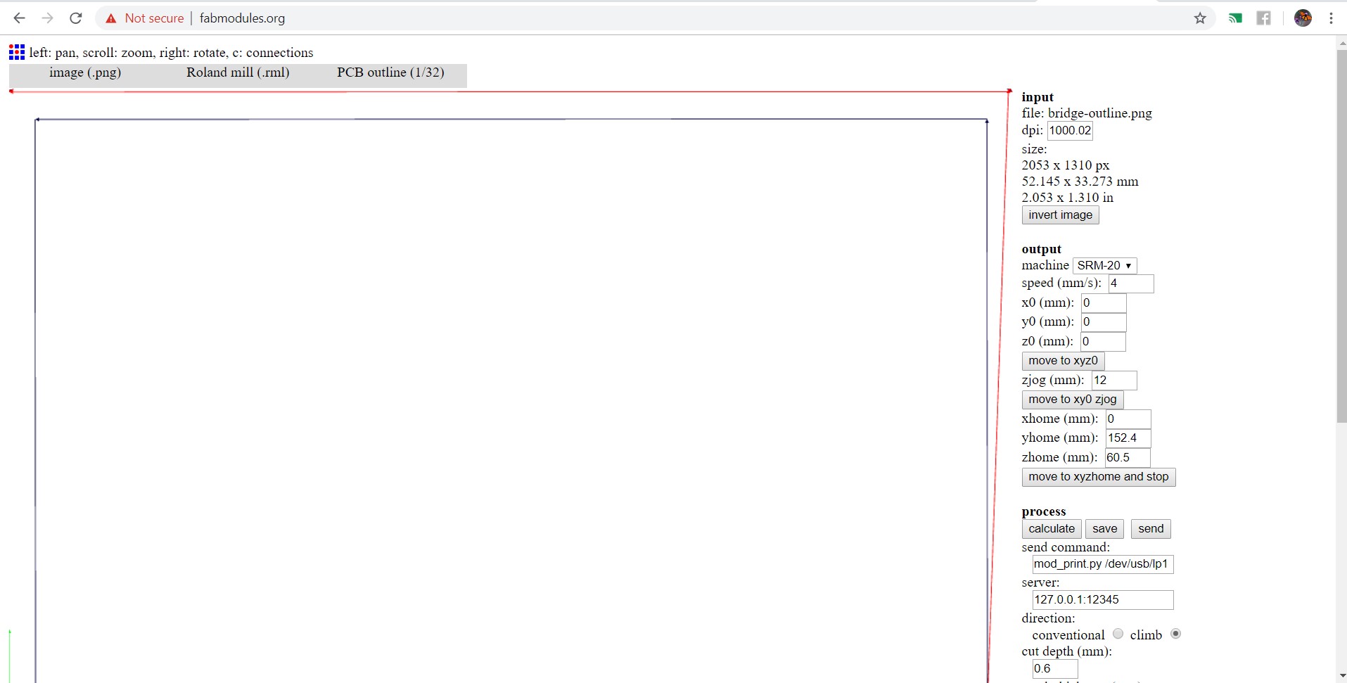
then I make .rml file using fab modules
2.Bridge - This board communicates with the serial port and other board with the help of FTDI cable.
Schematic diagram of my Bridge board
Routing and Export in .png file
PNG file
|

|
Making .rml file
I collected components as neil board required.
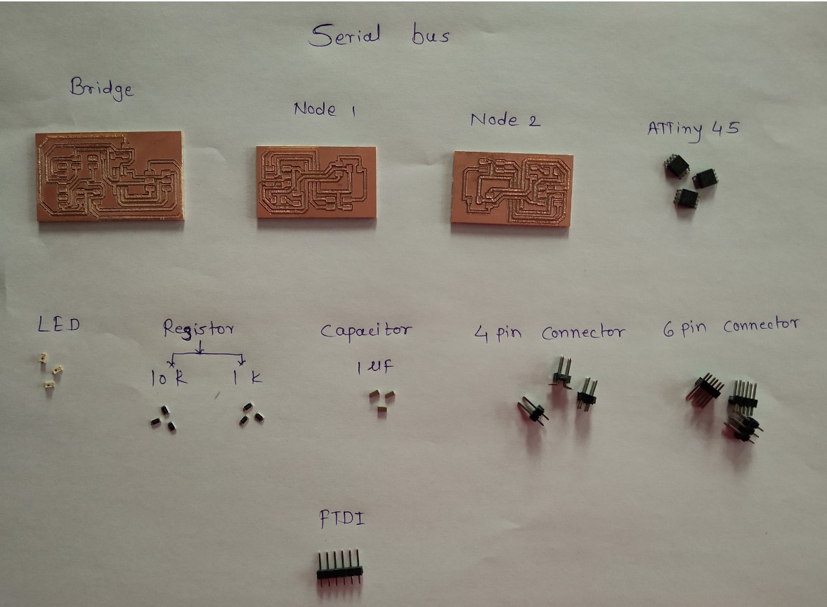
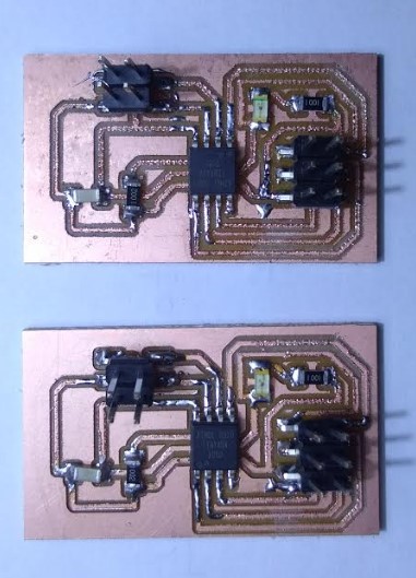
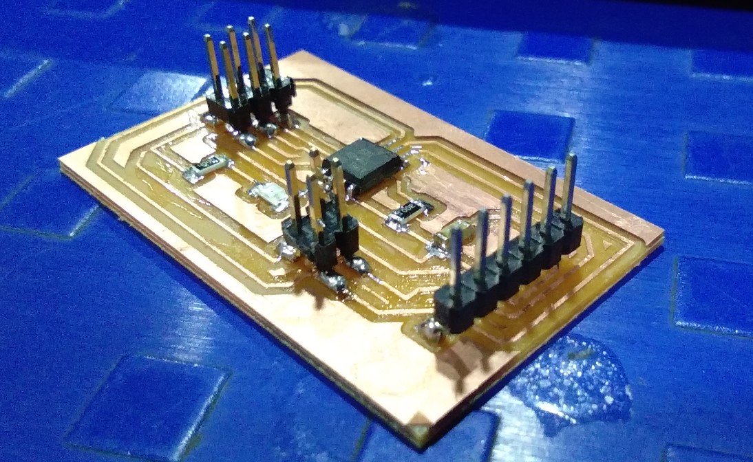
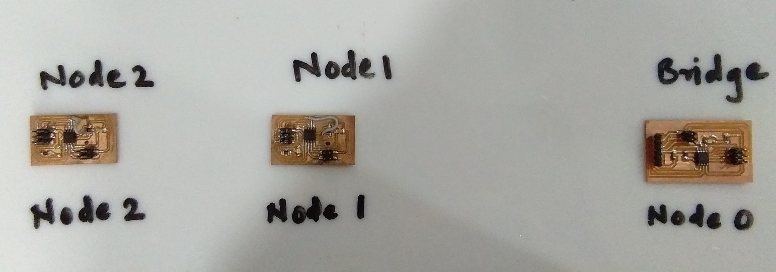
After designing I milled my three board (2 Node and 1 Bridge) on SRM20 Machine.then I solder it.
this image shown my 2 node board and 1 bridge board
Programming
After soldering and testing of the board then I going to program it and its burn the program as well.
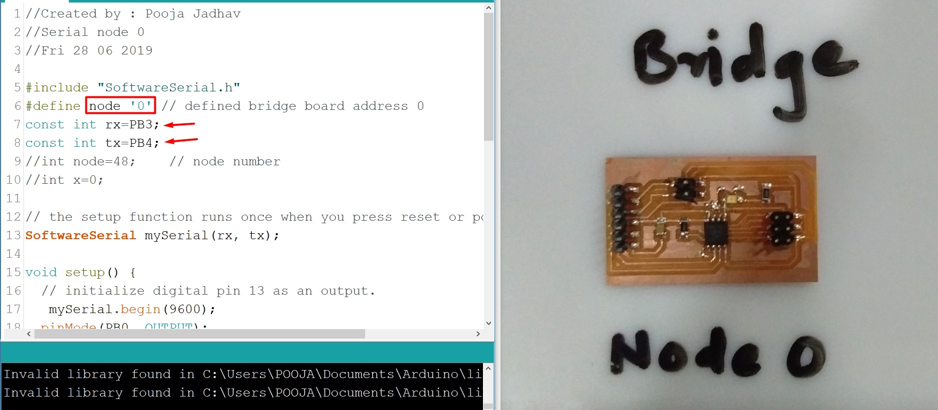
In my bridge board . I defined Node Address is 0.The code for Bridge serial communication with node.
Same code but need to change the node ID in the code.In my Node board . I defined Node Address is 1 for first node board and defined another node address is 2 for second board.
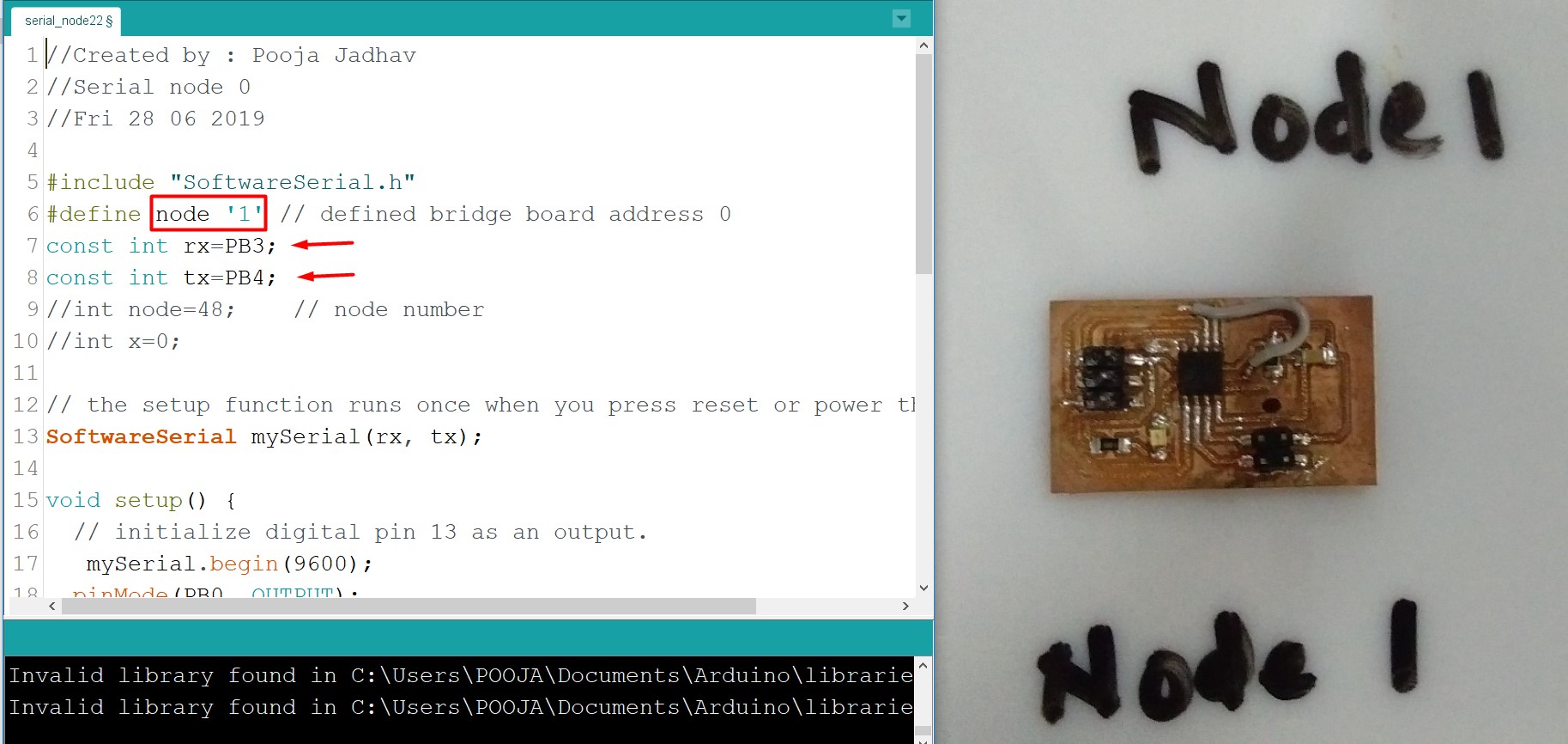
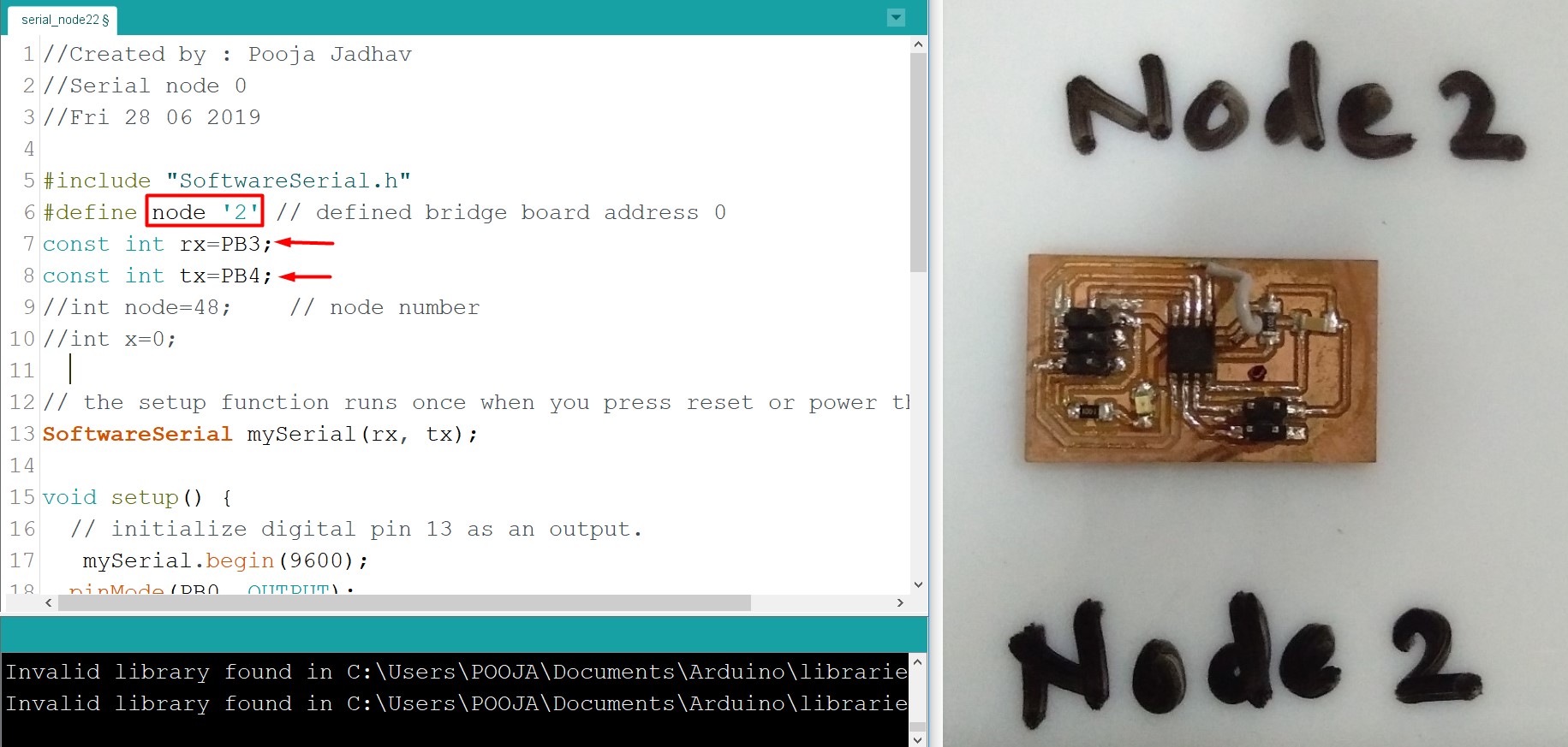
Here is the program
                //Created by : Pooja Jadhav
//Serial node 0
//Fri 28 06 2019

#include "SoftwareSerial.h"
#define node '2' // defined bridge board address 0
const int rx=PB3;
const int tx=PB4;
//int node=48;    // node number
//int x=0;

// the setup function runs once when you press reset or power the board
SoftwareSerial mySerial(rx, tx);

void setup() {
  // initialize digital pin 13 as an output.
   mySerial.begin(9600);
  pinMode(PB0, OUTPUT);
  digitalWrite(PB0, HIGH);
}

// the loop function runs over and over again forever
void loop()
{
  if(mySerial.available() > 0)

  {
    //mySerial.print("here");
    int x=mySerial.read();
    delay(1000);
   // mySerial.print(x);

  if (x==node)
    {
    digitalWrite(PB0, LOW);   // turn the LED on (HIGH is the voltage level)
    delay(500);
    digitalWrite(PB0, HIGH);
    delay(500);

        }
  }
}
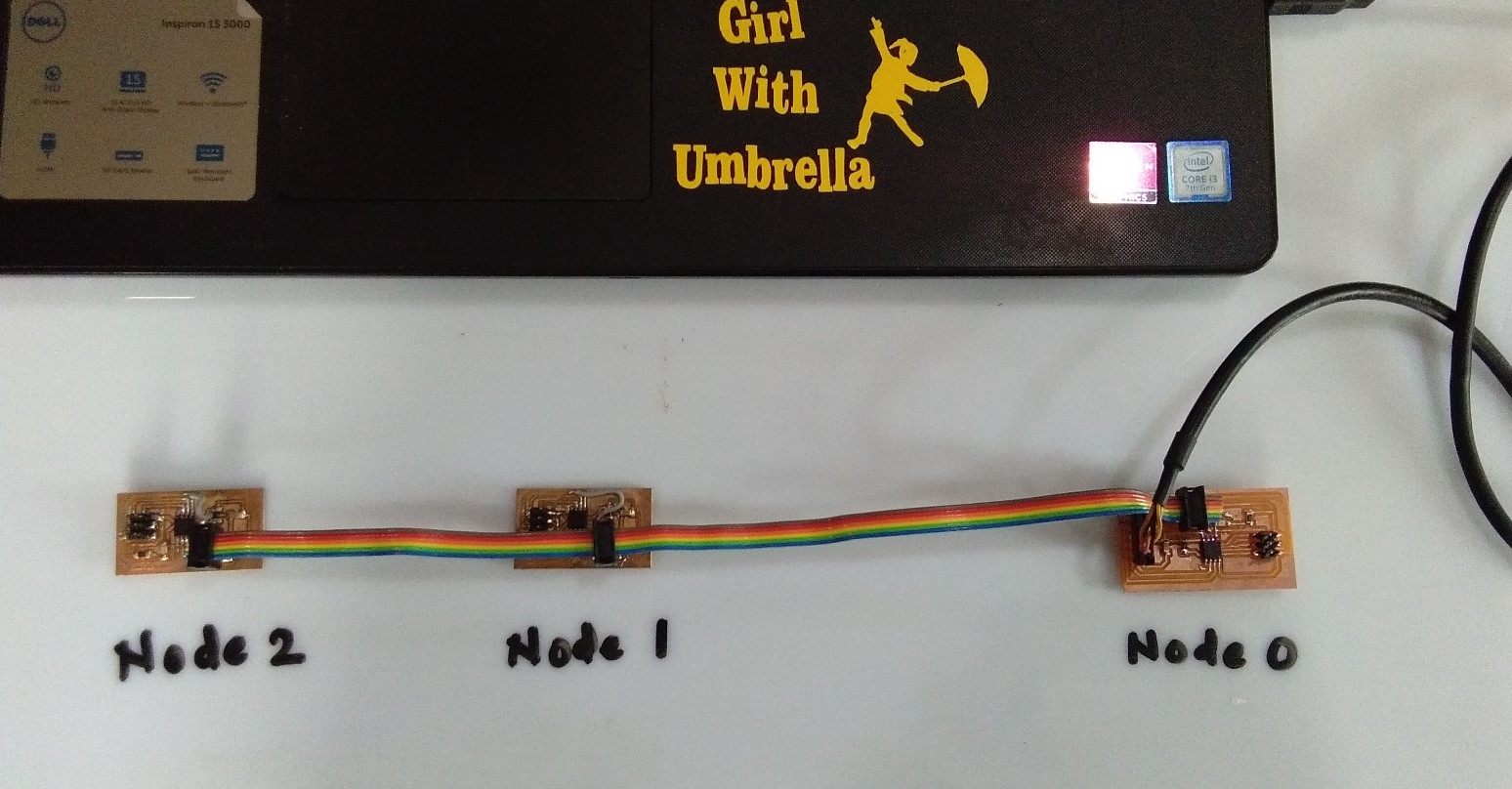
Below image shown bridge and node board.
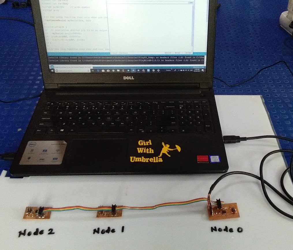
Then I arranged three board in serialy.I used 3x3 Pin header with Ribben cable to make a communication Bus.I connected RX and TX from each board using ribben cable. Then I checked continuity.
In serial monitor, When I pressed 0 and clicked Enter then Blinking LED of bridge board beacause I defined 0 Node ID for bridge board. Same think in Node board.but in Node board I pressed 1 and 2 Node ID.
here the video
You can Download Board file
You can Download .PNG file
You can Download .rml file
You can Download original code
Learning Outcome
In this week we tried different things and I understand the master-slave relation.but this assignment is really hard for me.In communication I got many errors some of board,program and some of my mistake.but from this error I got a lots of knowlegde of Network and communicatio.