Weekly Task
Group assignment:
measure the analog levels and digital signals in an input device
Individual assignment:
measure something: add a sensor to a microcontroller board that you have designed and read it
Introduction about Input devices
Electronics device which can get analog signal from out side and send to the controller and process it in digital signal (serial monitor in hexadecimal value) it know as input devices.
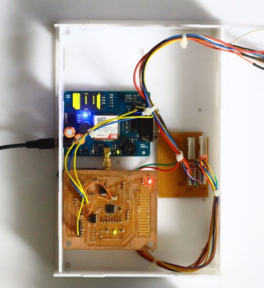
In this week we need to connect a sensor to a microcontroller and read that value, I decied to make my final project board using AT-mega 328 IC for microcontroller. my final project is Dam water Level. For inputs I need a water level sensor.I also made my input device that is Water level sensor
Sensor tested on Arudino
Before started design of my final project board.I tested some sensor on arudino like ultrasonic sensor,LDR light sensor,temperature sensor.
LDR Light sensorGroup Assignment
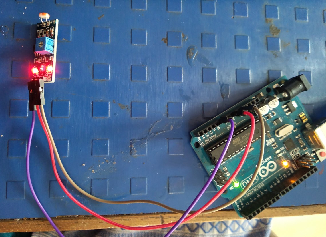
LDR - A Light Detector or a Light Sensor is a device or circuit that detects the intensity of the light incident on it. Different types of light detectors are LDRs (or Light Dependent Resistors), Photo Diodes, Photo Transistors, etc.
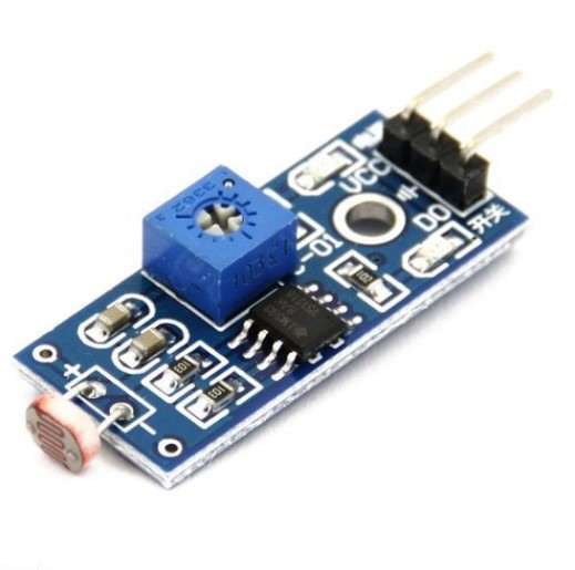
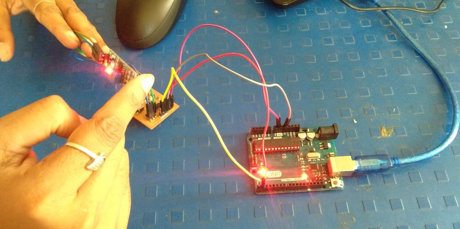
I connected LDR sensor to arudino
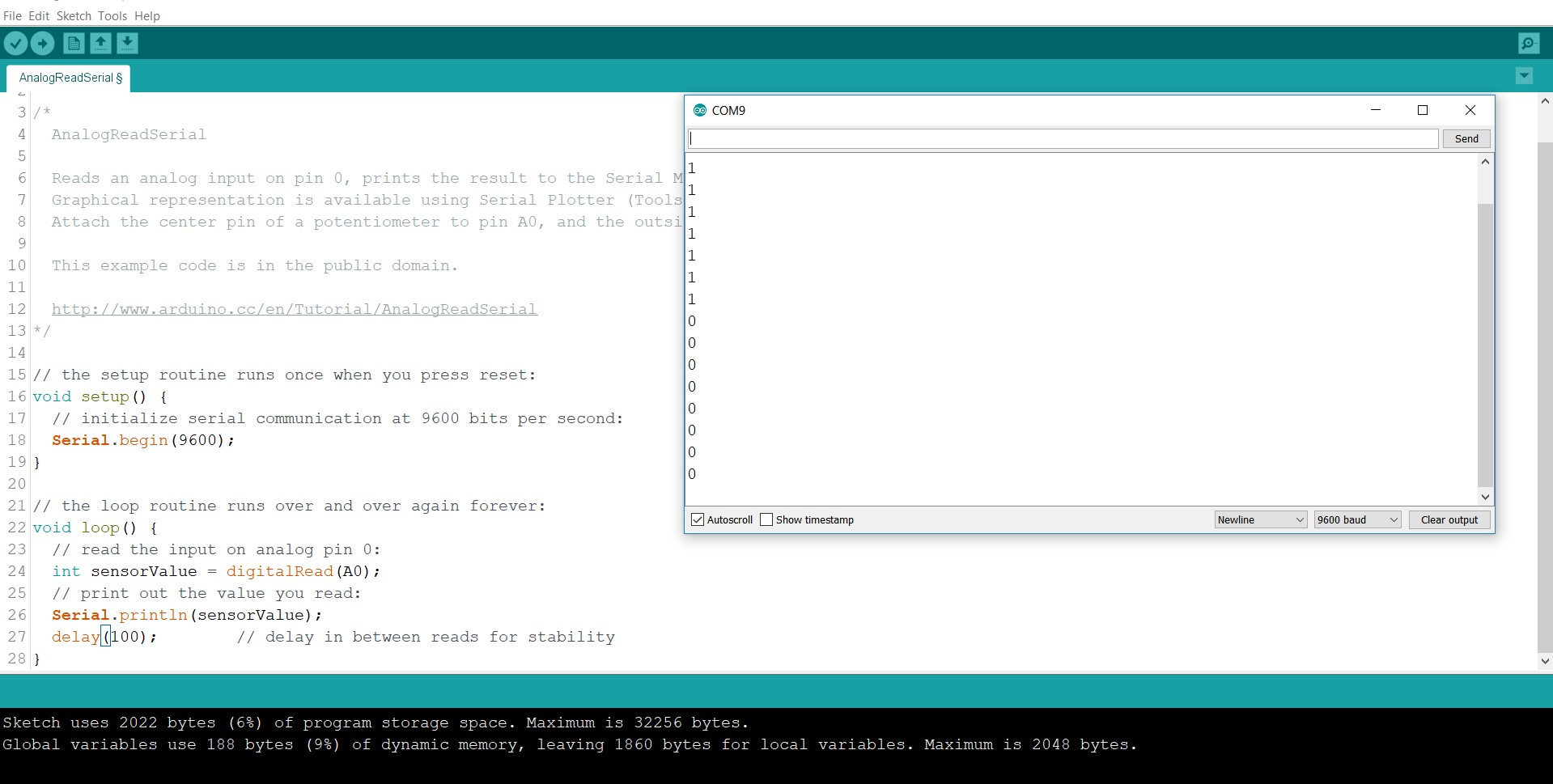
opened Arduino -->Example --> Basic --> AnalogReadSerial
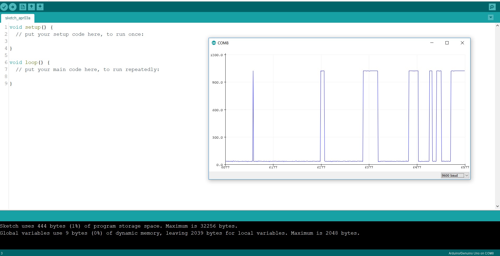
I connected LDR to arduino using jumper wires.and uploaded program.I got the output..when LDR sensor is in light then I got a value 1,either I got a 0 value.
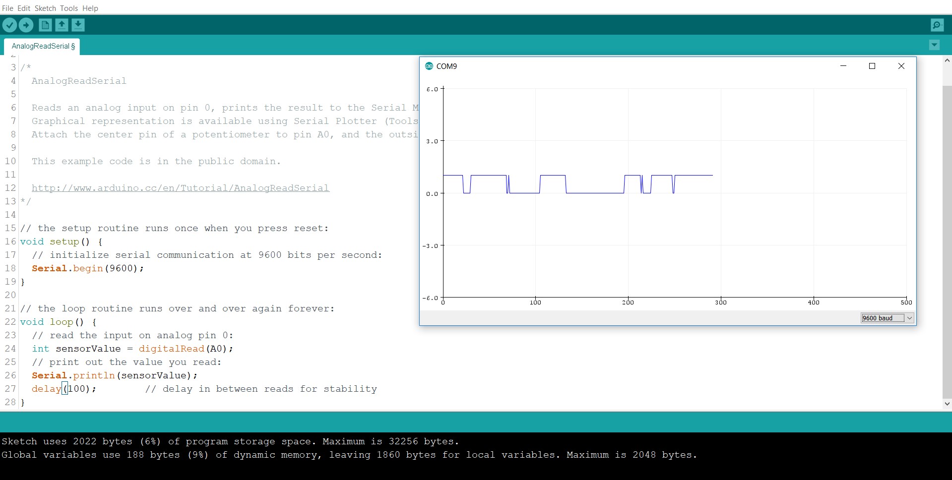
Here I see the sine Waves....
Same sensor I tried to did on my hello Board.I connected LDR to my hello board.Firstly I got the errors many times.then I checked the softwareserial Library.
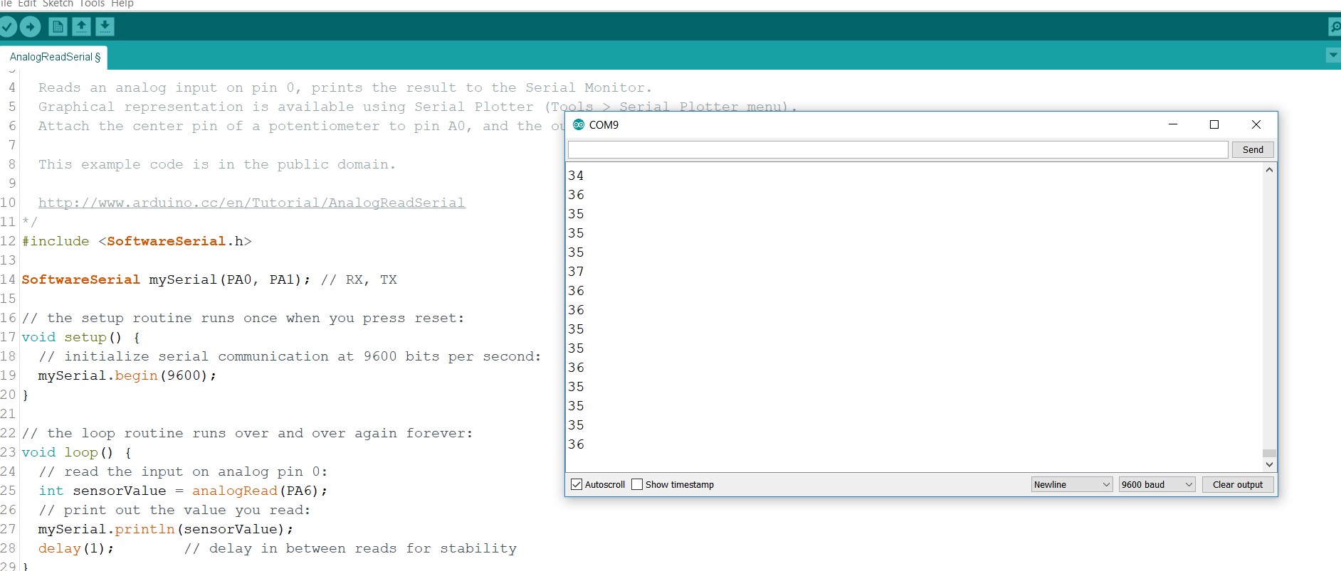
Uploaded program then I got a output..Sinewaves...using Hello board.
Individual Assignment
Water level sensor
Level sensors are used to monitor and regulate levels of a particular free-flowing substance within a contained space.
Water level sensor Features
Design and Fabricate Board
Using Eagle and Rolland SRM-20 milling machine, I made two PCB for sensing Water level sensor. And AT-mega 328 microcontroller Board.I want to measure water level in my project so I decided to make water level sensor in this assignment.
In water level sensor I need 5 connectors for checking level in different steps.So,I took 5 connectors (2 pins header),registors (In one circuit I took two registor) and 8 pin header for input(5 for inputs and 2 for GND and VCC). Firstly I arranged components and join it using jumper wires.then i checked erros.then I got a one error,I cleared it and clicked on switch board.
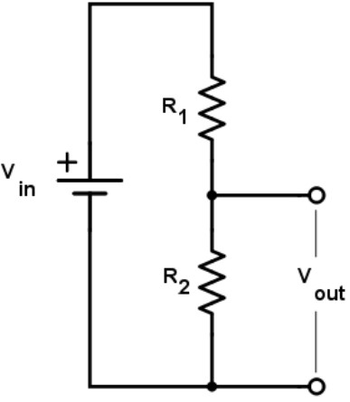
For Design this sensor I used voltage divider circuit.
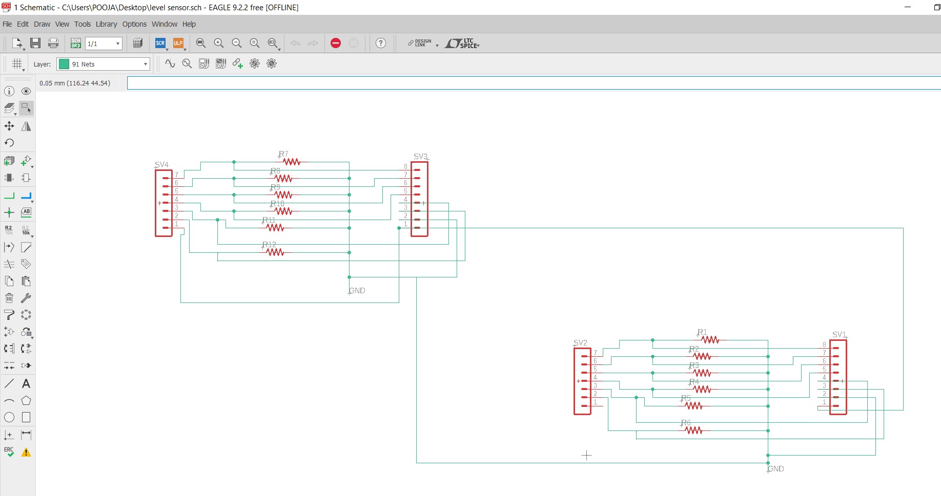
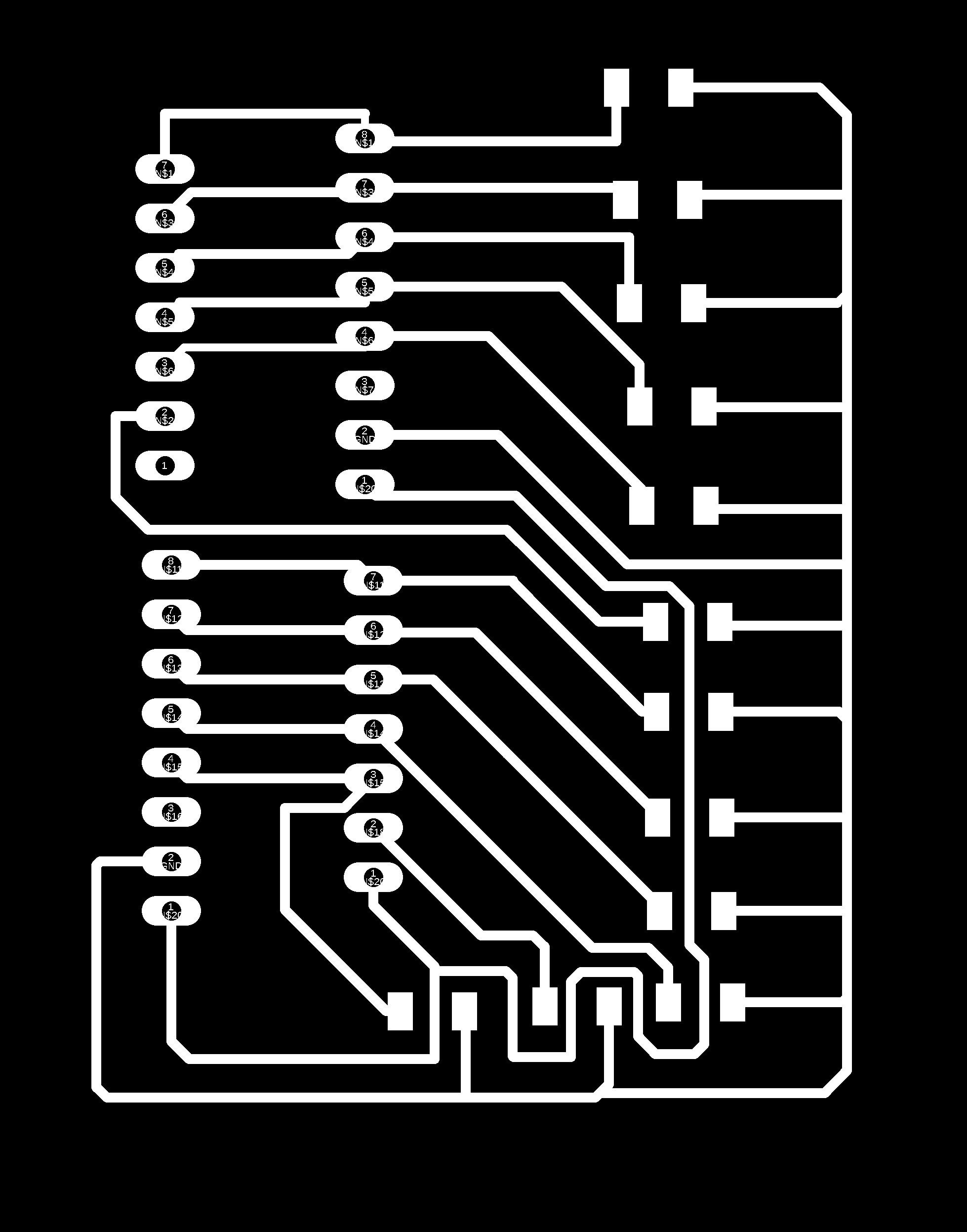
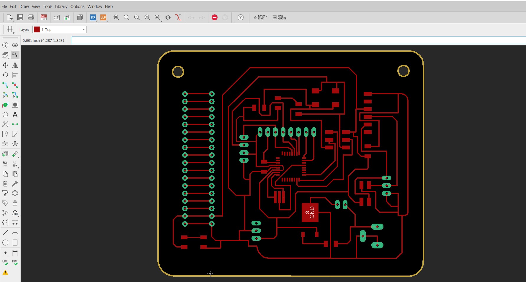
Then I routed my board and checked the DRC. Here routing is done.
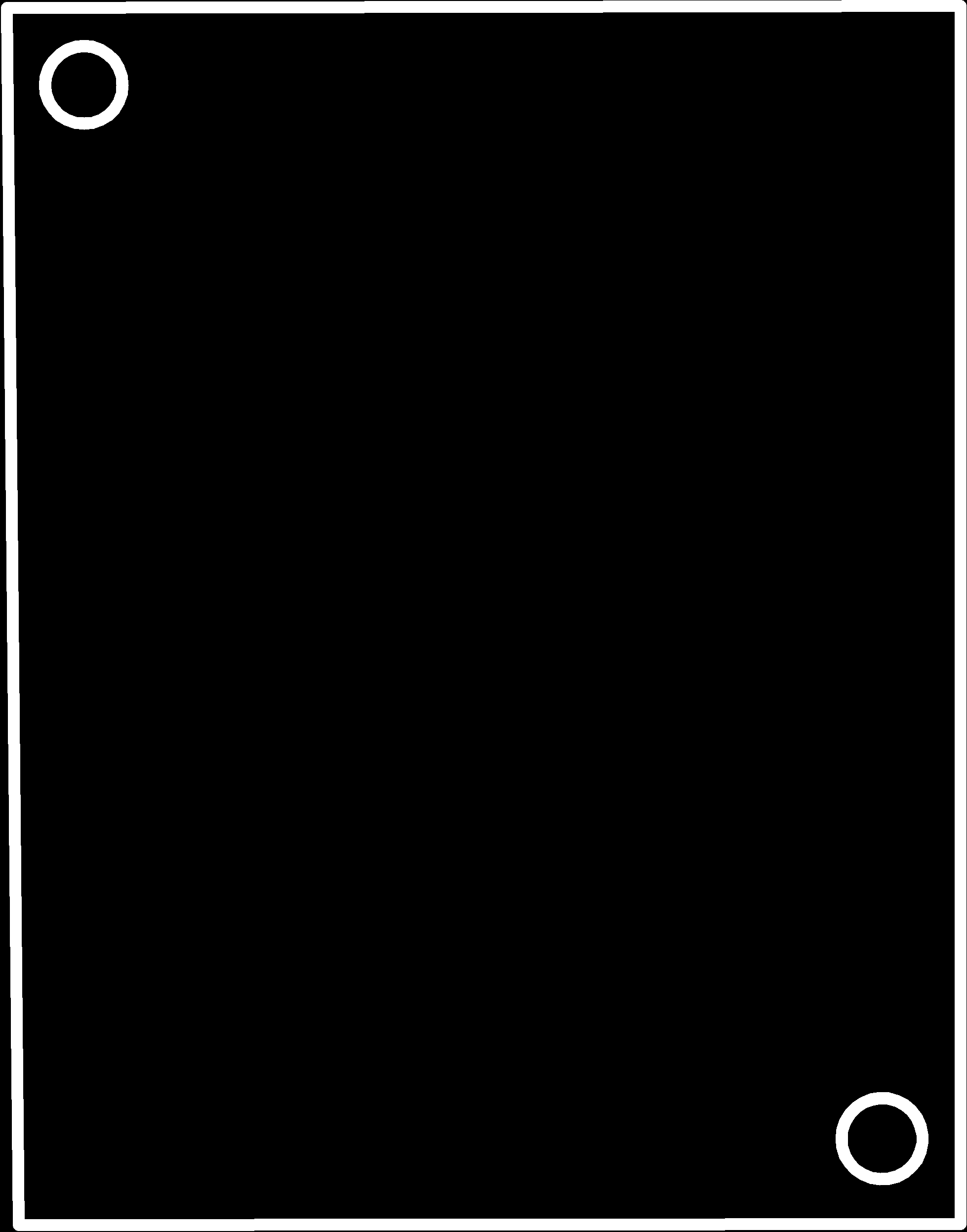
And saved the board in .png format.
|
|
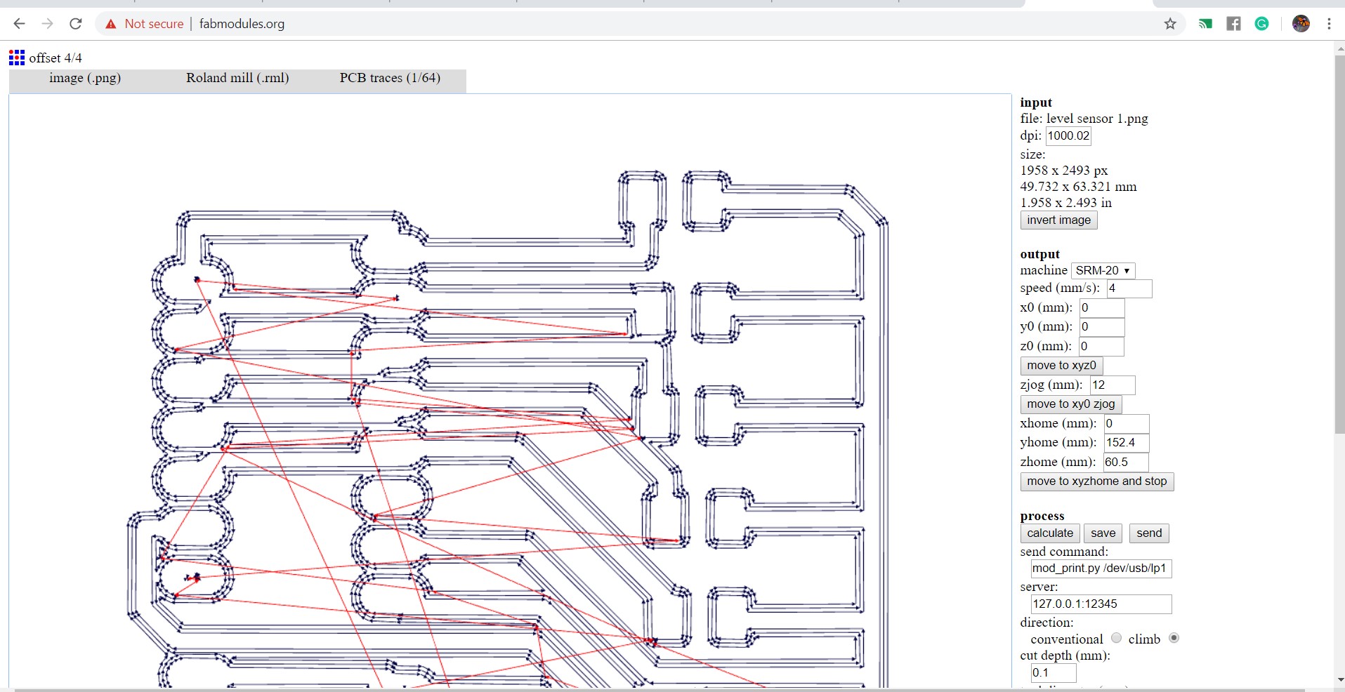
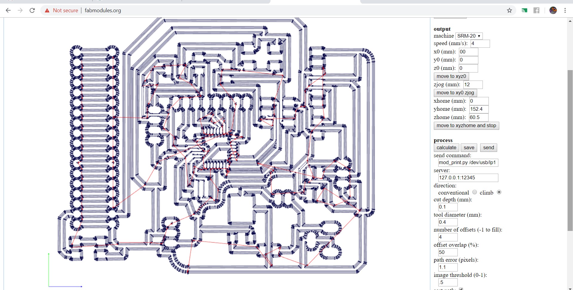
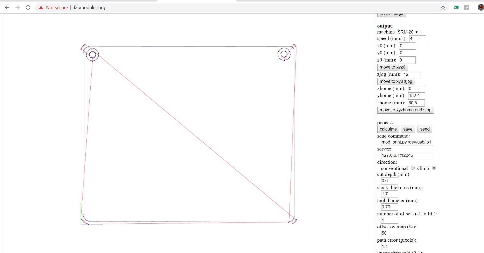
I used fabmodules for making .rml file
|
|
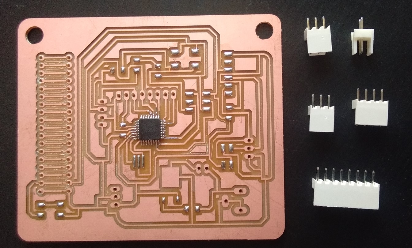
Then I made my microncontroller board using AT-mega 328p IC.
Atmega 328p-High performance micro chip developed by Atmel .It is a 8bit AVR RISC-based microcontroller combines 32KB ISP flash memory with read-while-write capabilities, 1024B EEPROM, 2KB SRAM, 23 general purpose I/O lines, 32 general purpose working registers, three flexible timer/counters with compare modes, internal and external interrupts, serial programmable USART, a byte-oriented 2-wire serial interface, SPI serial port, a 6-channel 10-bit A/D converter (8-channels in TQFP and QFN/MLF packages), programmable watchdog timer with internal oscillator, and five software selectable power saving modes. The device operates between 1.8-5.5 volts.
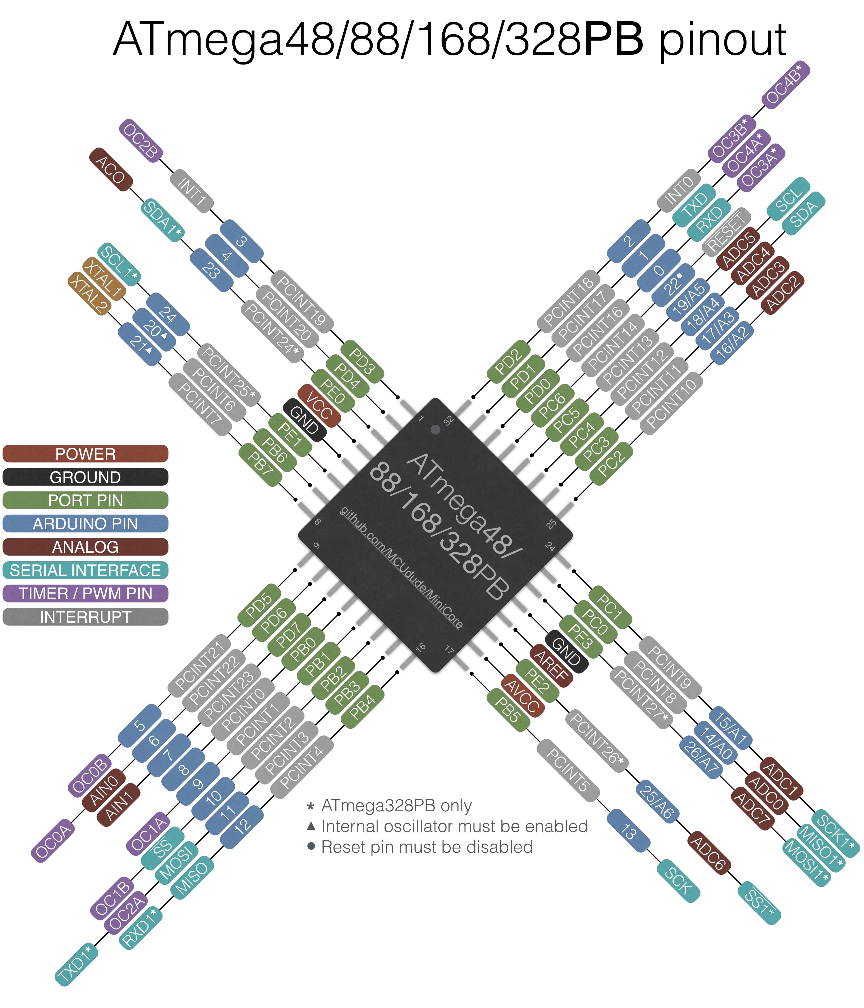
ATmega 328p-AU Pinout from Atmel Data Sheet
In the image above I taged the most important pins of ATmega328p-AU. In the folowing I will describe the fuction of those pins:
All Voltage supply Pins have to be connected. From the Data Sheet ATmega328p-AU:
Before started my board design I add Atmega 328p library in egale
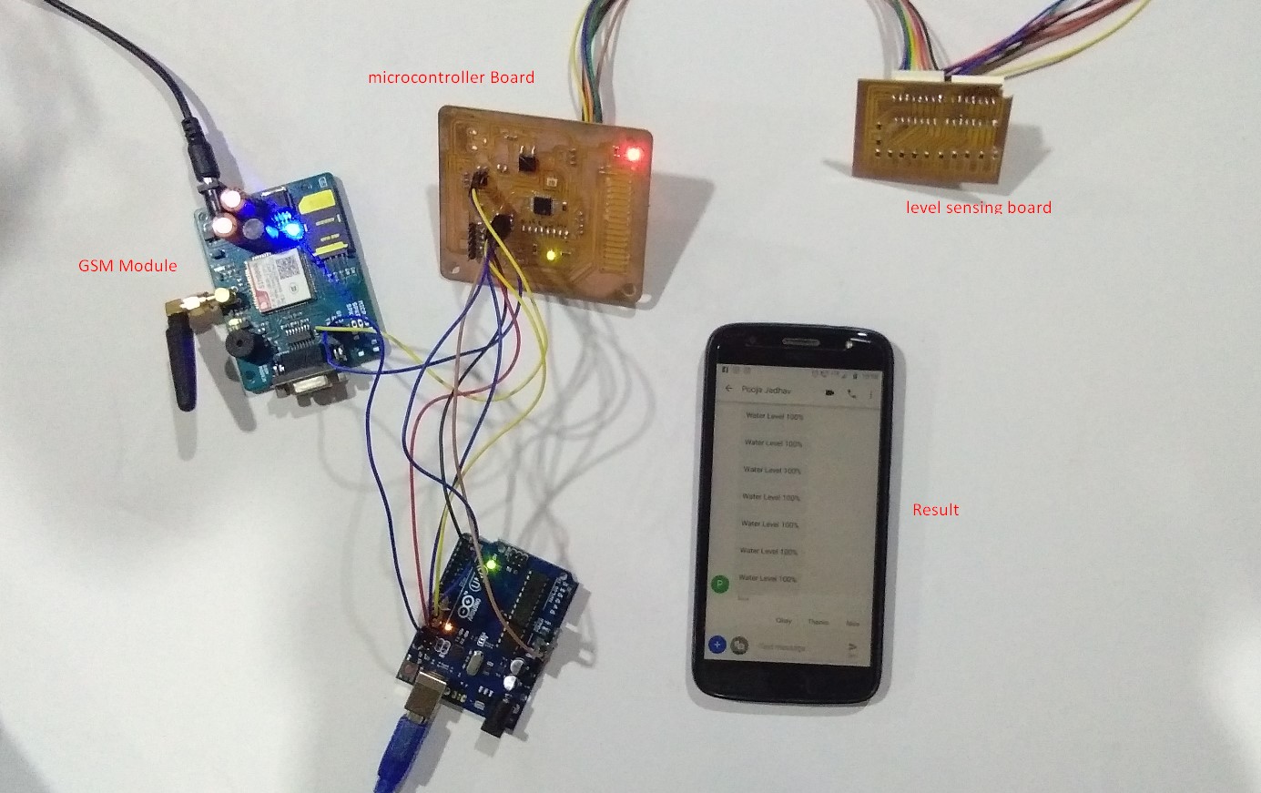
Open the eagle softawre and started schematics.my output board of final project is LED Matrix Display.I used GSM Module for sending messege receiver side to transmitter side.GSM module has 3 pins(RXD,TXD and GND),So,I took 3 pin header for output.
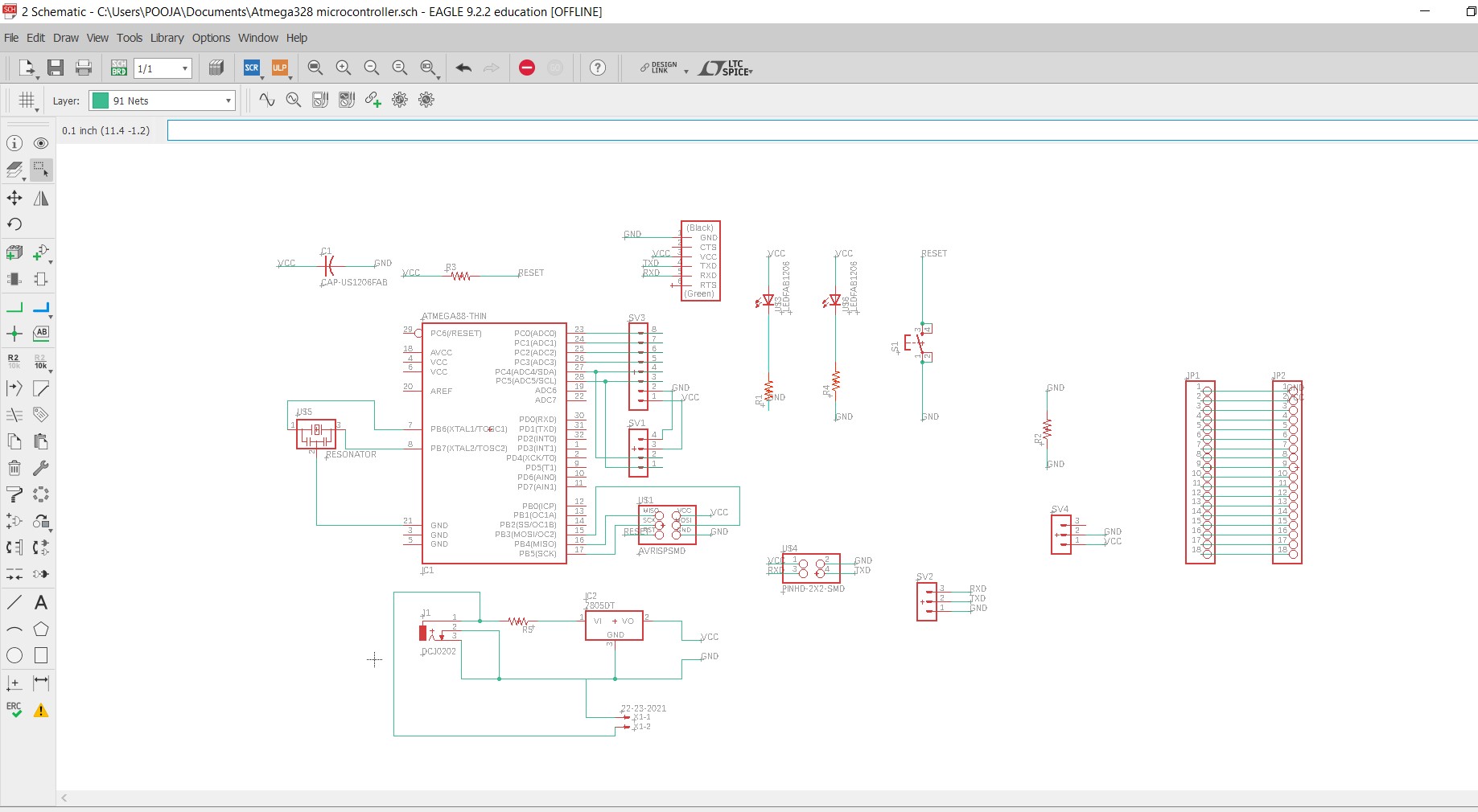
A 20Mhz resonator connected across the XTAL1 and XTAL2 pins.Join push button to reset pin and another pin of the switch is grounded.Crystal connected across the XTAL1 and XTAL2, add the load capacitances from the pins to ground. I used Resonator instead for Crystal oscillator because it already has capacitors inbuild.
I used 8 pin header for inputs from sensor.and also used 3 pin header for output(GSM Module).then I used LED for indicator,switch,power jack for supply.
After design the pcb in eagle and export the traces, dimension and dill paths separately, save it as png ( use monochrome mode to export the images )
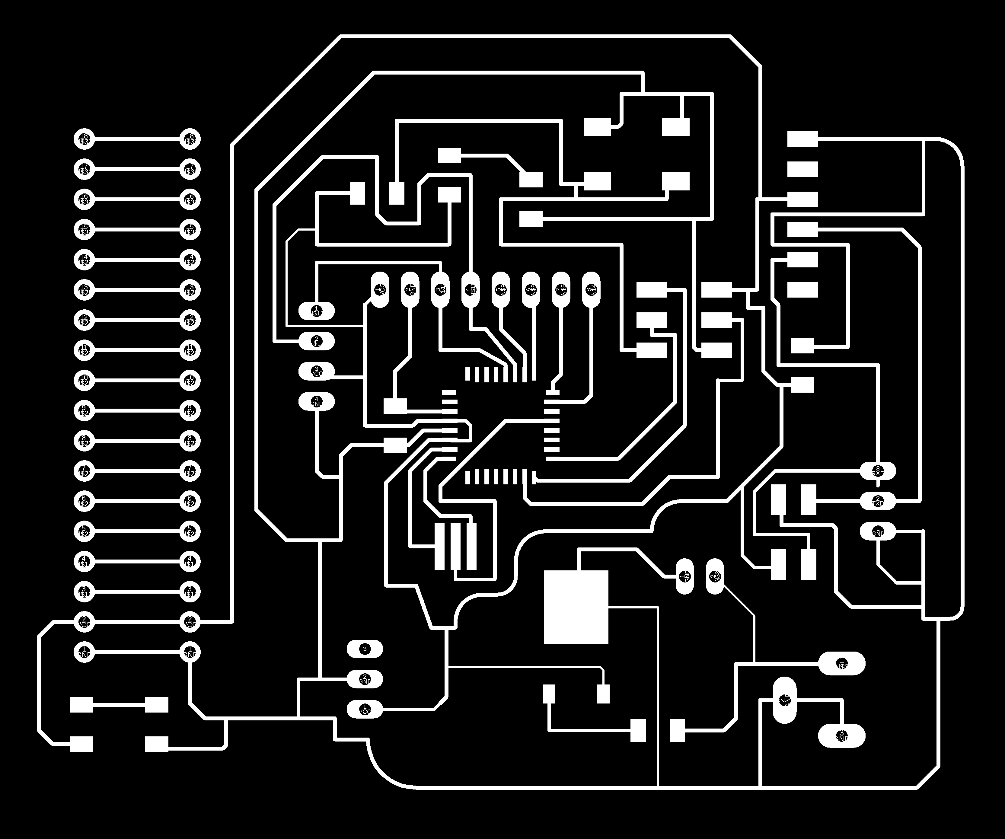
After opening the traces image in fabmodule and choose use 1/64 bit to mill the pcb.while drawing the traces I gave 0.012 inch as the trace width.
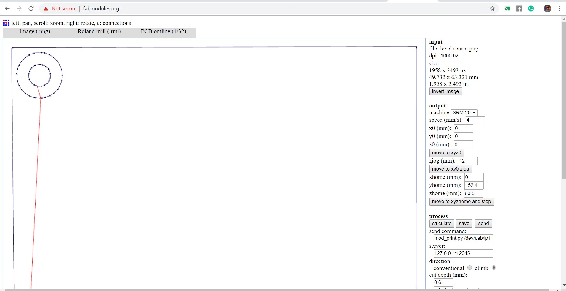
the outline image in fabmodule and choose use 1/32 bit to mill the pcb.
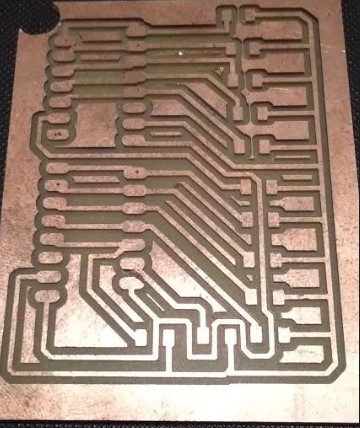
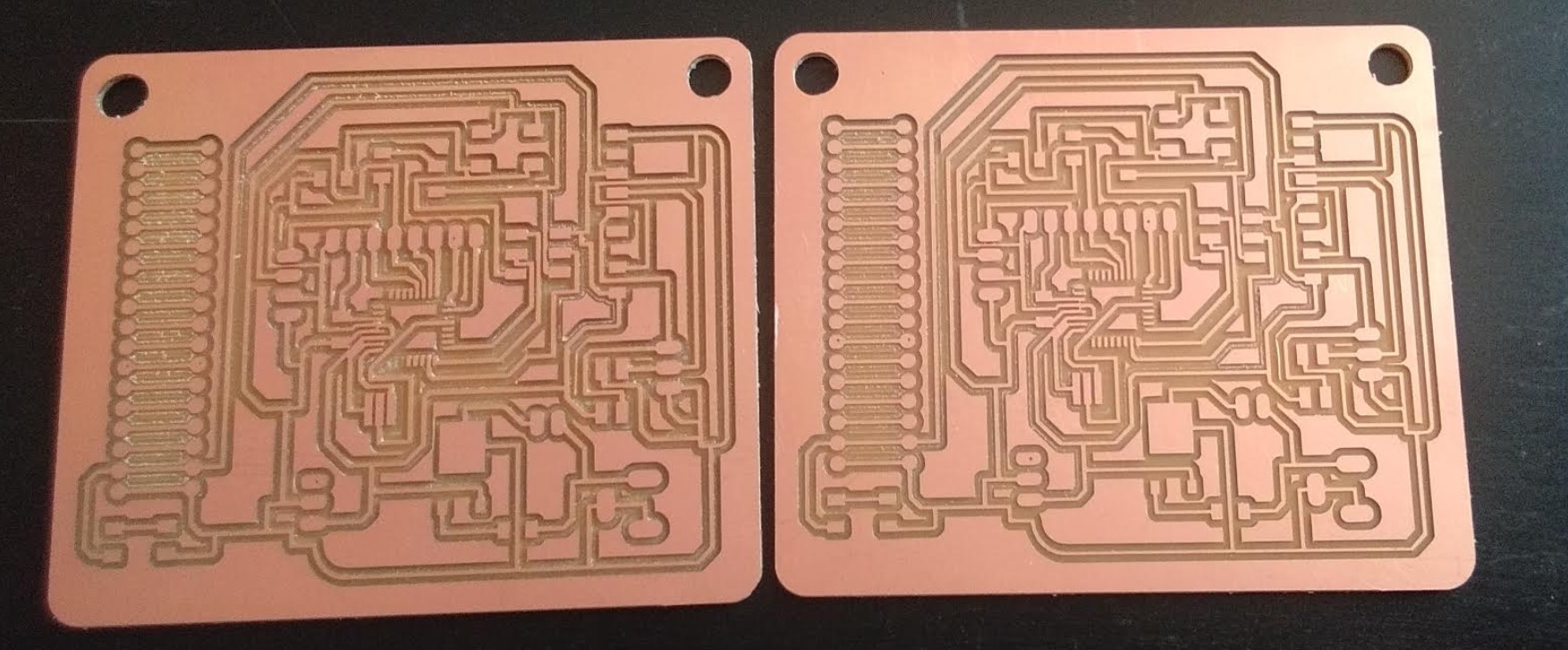
Then milling board.
I have made same board for my Output device
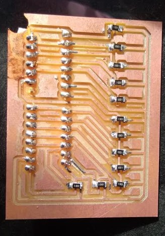
Soldering
What component I used?
- Atmega 328p
- 8 pin connector
- 4,3 and 2 pin connector
- LED
- Register 499 ohm
- Capacitor 10 microfarad
- 20mHz Resonator
Soldering board
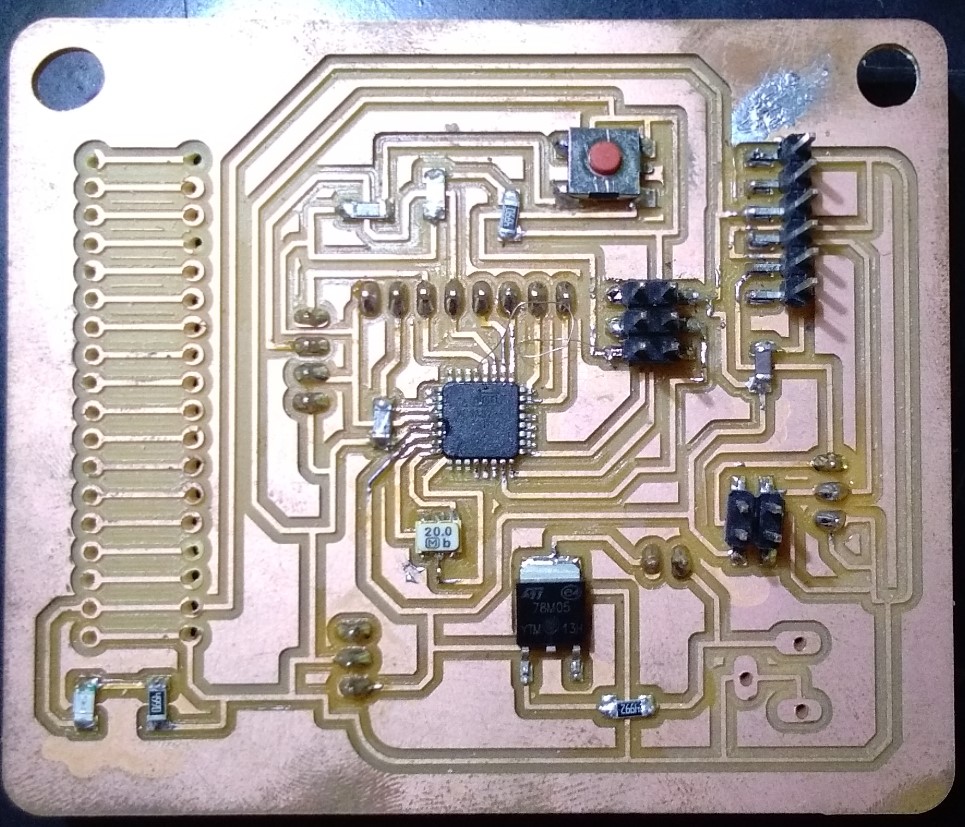
I have made a two module first is Transmitter side and second is receiver side.
Here is the code of Transmitter side.
                //Made on 10/06/2019
//Project by : Pooja Jadhav
//Transmitter code
//Dam water level controller


//GSM SIM800//
#include
SoftwareSerial mySerial(7,8); // RX, TX

void setup()
{
  Serial.begin(9600);// start serial port
  mySerial.begin(9600);
}

void loop()
{
     if (mySerial.available())
     Serial.write(mySerial.read());
     delay(10000); //Give enough time for GSM to register on Network
     SendSMS();    //Send one SMS
     //delay (60000);
     delay (60000);
   // while (1);

}

int level1 (int x)
{
   x = analogRead (A0);
 //Serial.println(x);
  return x;
}

int level2 (int y)
{
   y = analogRead (A1);
  //Serial.println(y);
  return y;
}

int level3 (int z)
{
   z = analogRead (A2);
 // Serial.println(z);
  return z;
}

int level4 (int p)
{
   p = analogRead (A3);
 // Serial.println(p);
  return p;
}

int level5 (int q)
{
   q = analogRead (A4);
 // Serial.println(q);
  return q;
}


void SendSMS()
{
  int a,b,c,d,e,f,g,h,i,j,k,l,m,n;
  a = level1(h);
  b = level2(i);
  c = level3(j);
  d = level4(k);
  e = level5(l);
 // f = level2(m);
 // g = level2(n);

  Serial.println(a);Serial.println(b);Serial.println(c);Serial.println(d);Serial.println(e);

  mySerial.println("AT+CMGF=1");    //To send SMS in Text Mode
  delay(1000);
  mySerial.println("AT+CMGS=\"+919112735153\"\r"); //Change to destination phone number
 // mySerial.println("AT+CMGS=\"+918380862704\"\r");
  delay(1000);
  //mySerial.println ("Water Level 100%");

   if (a > 100 && b > 100 && c > 100 && d > 100 && e > 100 )
 {
    mySerial.println ("Water Level 100%");
    Serial.println ("Water Level 100%");
   delay(1000);
 }


 else if (a > 100 && b > 100 && c > 100 && d > 100 )
 {
    mySerial.println ("Water Level 75%");
    Serial.println ("Water Level 75%");
     delay(1000);
 }


 else if (a > 100 && b > 100 && c > 100 )
 {
    mySerial.println ("Water Level 50%");
    Serial.println ("Water Level 50%");
     delay(1000);
 }

 else if (a > 100 && b > 100 )
 {
    mySerial.println ("Water Level 25%");
    Serial.println ("Water Level 25%");
    delay(1000);
 }

  else if (a > 100 && b <= 100)
 {
    mySerial.println ("Water Level  5%");
    Serial.println ("Water Level  5%");
    delay(1000);
 }

 else if (a < 100 && b < 100 && c < 100 && d < 100 && e < 100 )
 {
    mySerial.println ("Water Level  0%");
    Serial.println ("Water Level  0%");
    delay(1000);
 }

   mySerial.println((char)26); //the stopping character Ctrl+Z
  delay(500);


}
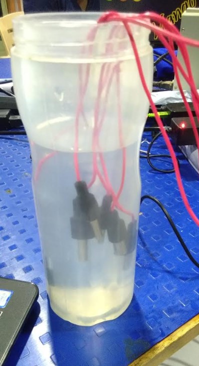
Before Installing On Dam I tested it own our space.I tested it on bottle.
How to work it?- I used level sensor for sensing the water level in Dam.Water have a good conductive Electricity.when sensor touch to water they shot and send data.
For the communication I used GSM Sim800A Module.
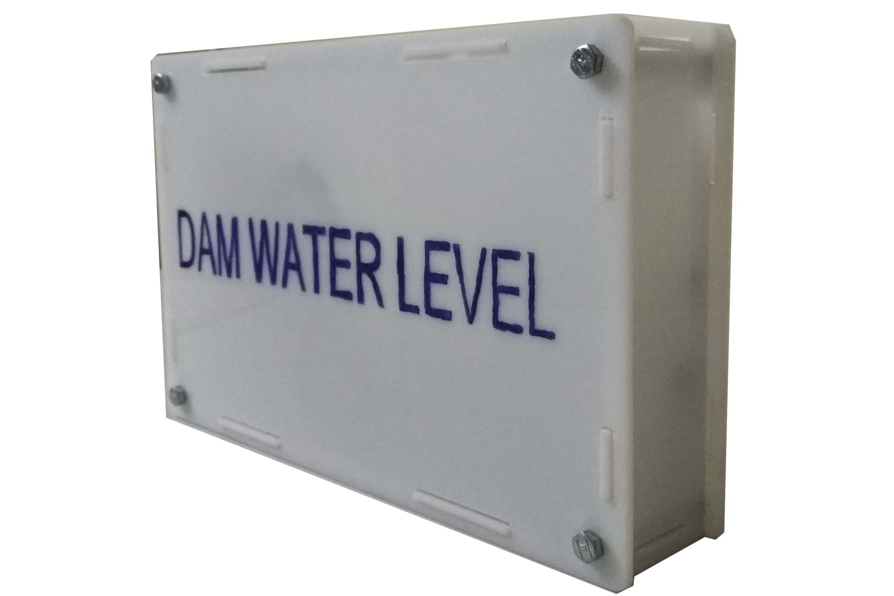
Then I made casing design using laser cutter
It looks like this
This video shows the Inputs from water level sensor.
You can Download Board file
You can Download PNG File
You can Download .rml file
learning Outcomes
In this week I made my water sensing board using water level sensor and microcontroller board using Atmega328p.I mostly learning communication part using gsm module. and also learn how to sense water.