Weekly Task
Group assignment:
measure the power consumption of an output device.
Individual assignment:
add an output device to a micro controller board you've designed, and program it to do something
An output device is any piece of hardware item which utilizes whatever data and commands from your micro controller/processor in order to perform a task.
In my final project, I made input device i,e water level sensor.for showing the output I used LED matrix display .
I wrote description about Atmega 328p Ic in previous week.I decided add output device.I have made two same board one for input and one is my output.actually this is my final project board .I used it Input and output device also.
In the previous week I made water level sensor and microcontroller board using Atmega-328p IC. I have made two similar board for Input and Output device.
For Input I used water level sensor.after checking the level, it shows on the display. so,I plan to add LED matrix Display board that displays the water level in percentage.
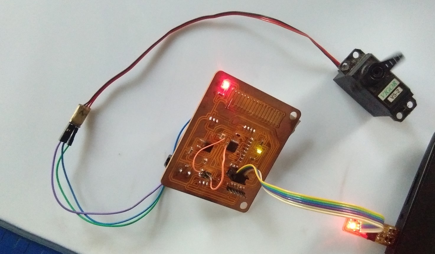
For output I controlling servo motor from my board.
Servo MotorA servomotor is a rotary actuator or linear actuator that allows for precise control of angular or linear position, velocity and acceleration.It consists of a suitable motor coupled to a sensor for position feedback. It also requires a relatively sophisticated controller, often a dedicated module designed specifically for use with servomotors. (from wikipedia)
for the output I used run servo motor on my board
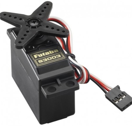
Servo motor have 3 pins
Firstly I upload program to my board through Arudino as ISP. Then I connected this wired to my atmega board.
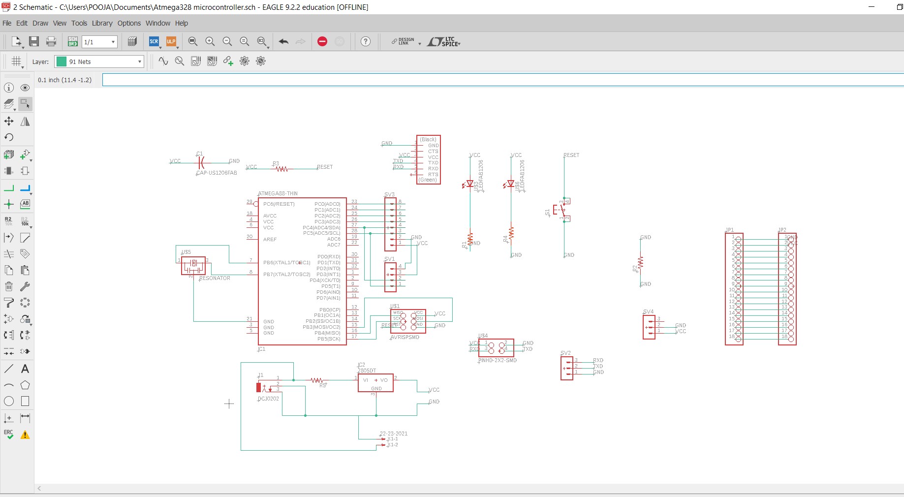
schematic
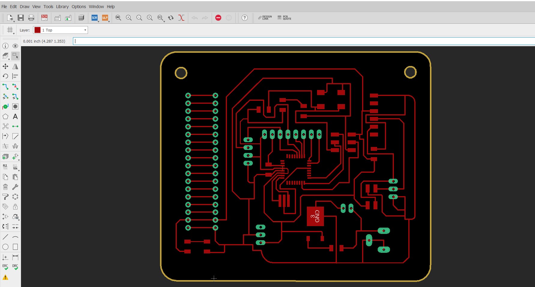
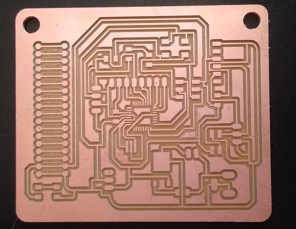
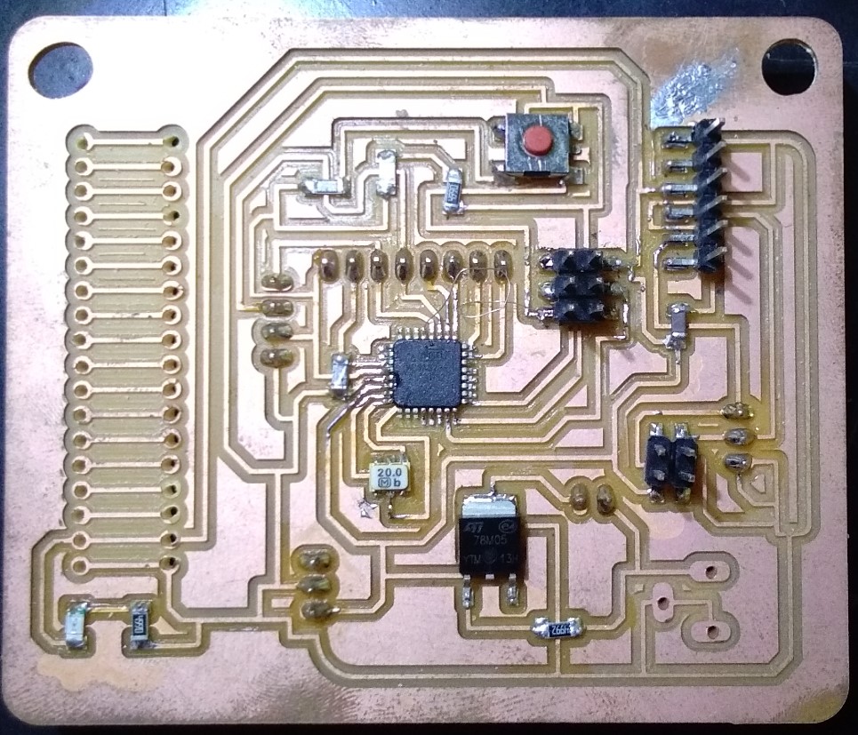
My ATmega328p Board final Layout:
save my file in .png file.
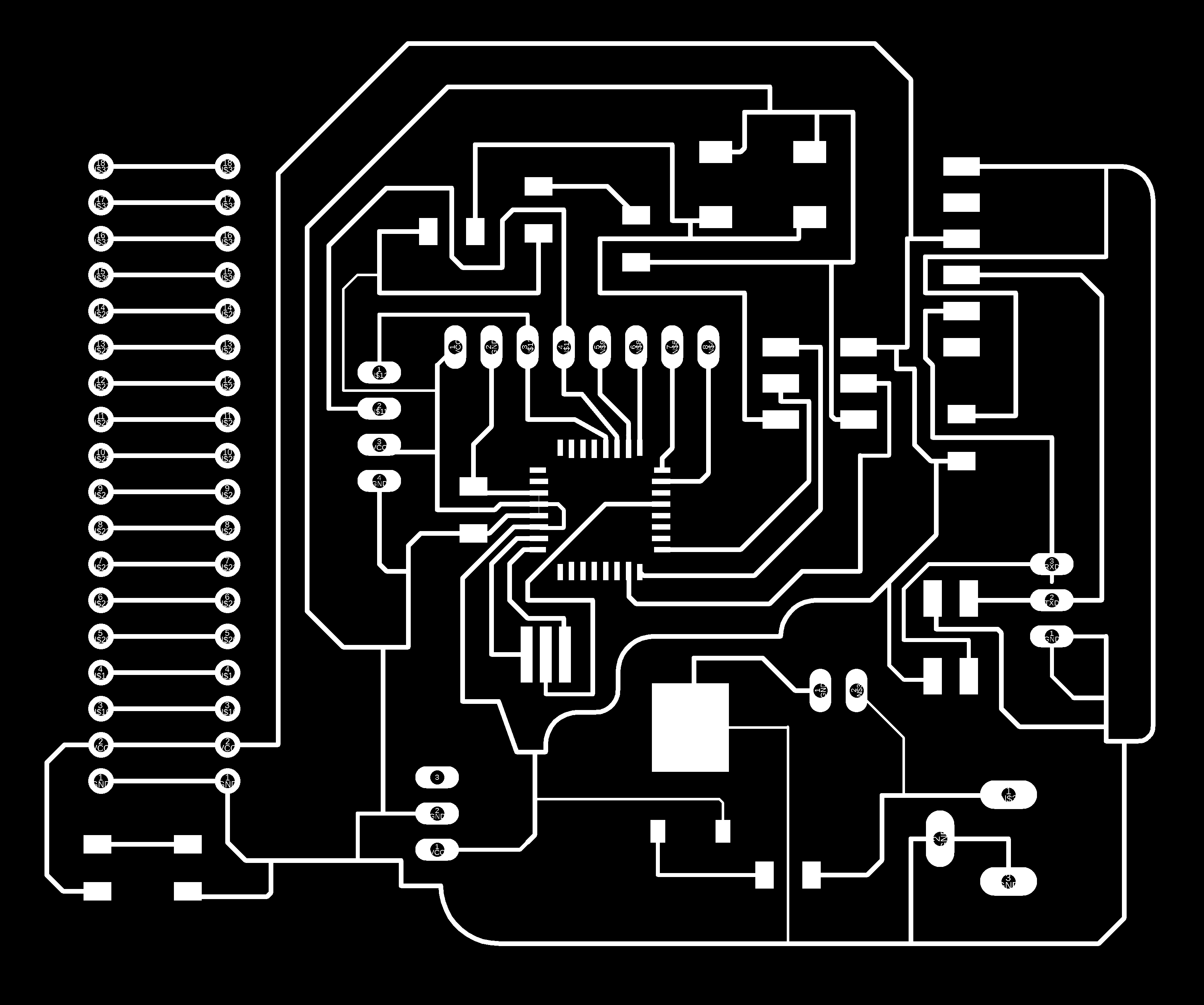
|
|
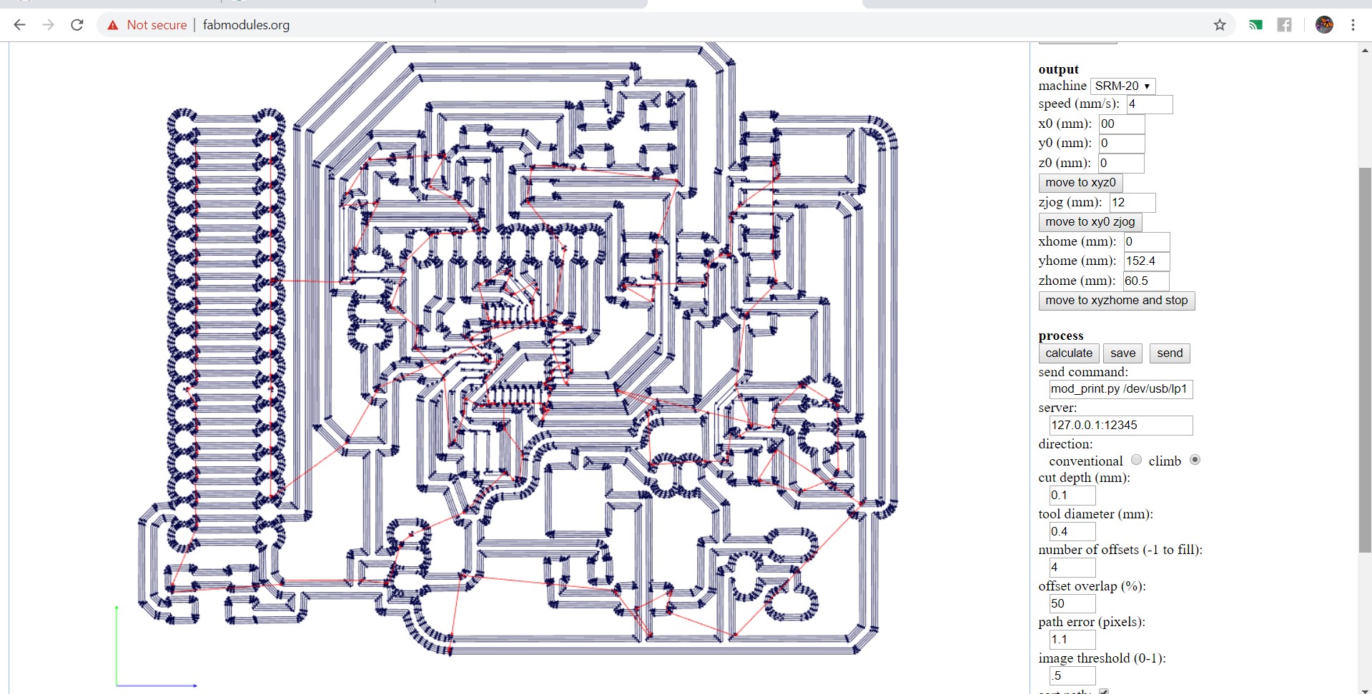
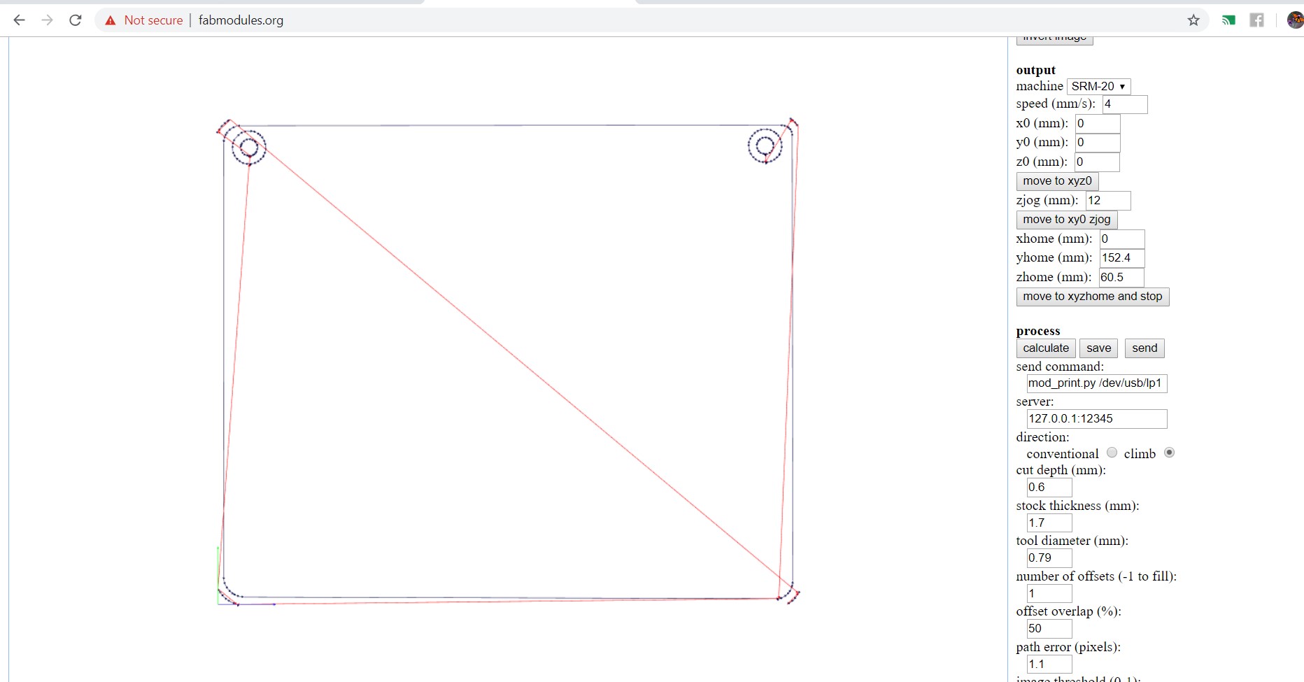
then make .rml file using Fabmodule.
program for servo motor
                 #include

Servo myservo;  // create servo object to control a servo
// twelve servo objects can be created on most boards

int pos = 0;    // variable to store the servo position

void setup() {
  myservo.attach(9);  // attaches the servo on pin 9 to the servo object
}

void loop() {
  for (pos = 0; pos <= 180; pos += 1) { // goes from 0 degrees to 180 degrees
    // in steps of 1 degree
    myservo.write(pos);              // tell servo to go to position in variable 'pos'
    delay(15);                       // waits 15ms for the servo to reach the position
  }
  for (pos = 180; pos >= 0; pos -= 1) { // goes from 180 degrees to 0 degrees
    myservo.write(pos);              // tell servo to go to position in variable 'pos'
    delay(15);                       // waits 15ms for the servo to reach the position
  }
}
video shows the sweep motor from my board
This Atmega board Actually is my final project board. I used it as output board. for the output I choose servo motor and LCD Display.
That time my FabISP did not work beacause of detection and troubleshooting problem. So, I used Commerial Arduino board for the just only programming.
I solved the problem regarding FabISP. and program it.
LCD Display
LCD modules are vey commonly used in most embedded projects, the reason being its cheap price, availability and programmer friendly.
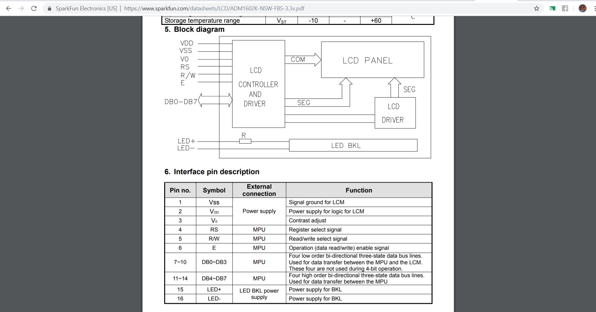
16×2 LCD is named so because; it has 16 Columns and 2 Rows. There are a lot of combinations available like, 8×1, 8×2, 10×2, 16×1, etc. but the most used one is the 16×2 LCD. So, it will have (16×2=32) 32 characters in total and each character will be made of 5×8 Pixel Dots.I followed the LCD display datasheet.
Pinout diagram of LCD Display
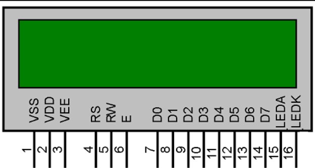
Description of pins
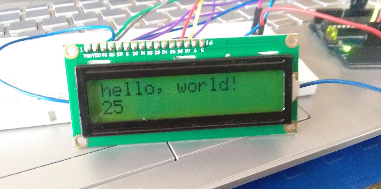
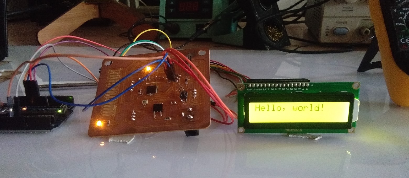
For Output design I tried to used 16 X 2 LCD display.I tested hello world program using arudino.
I go to Examples-->LiquidCrystal-->Hello world.
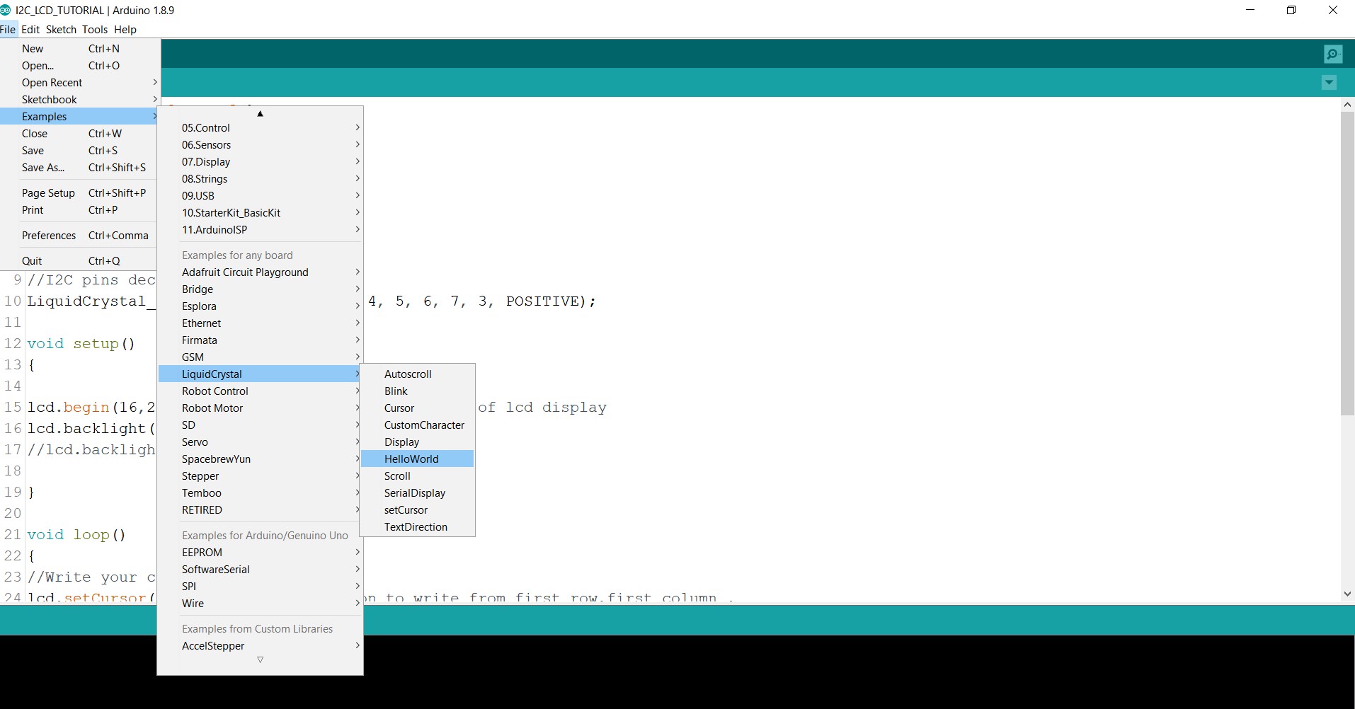
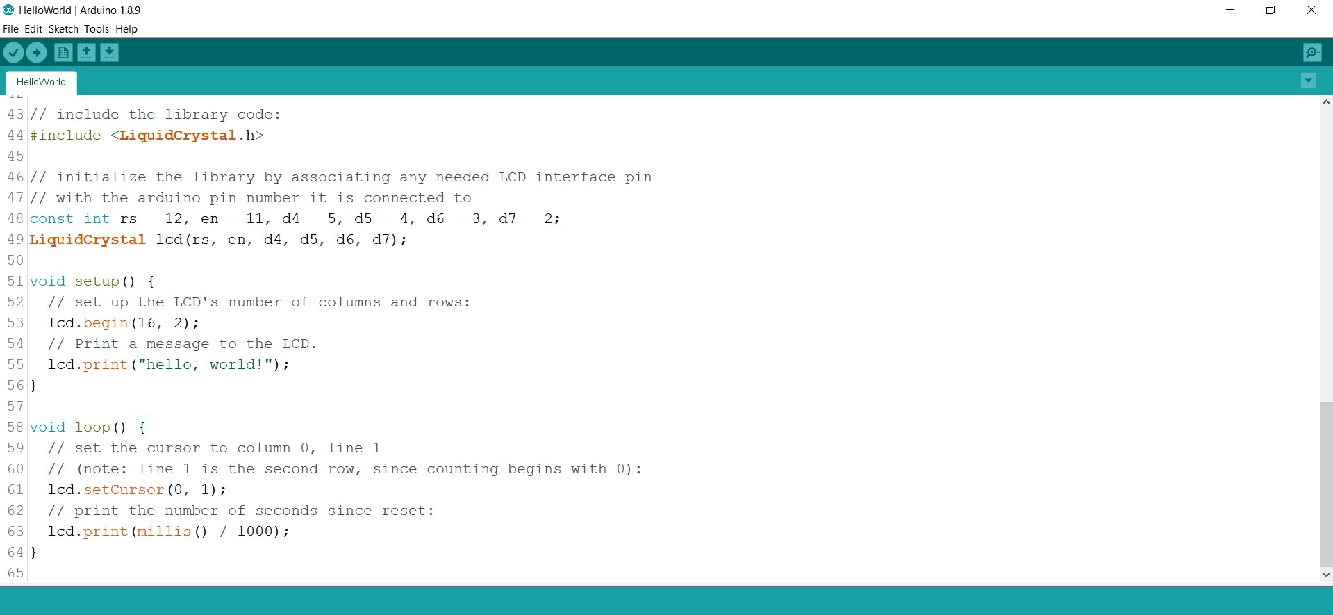
Here is the Program...
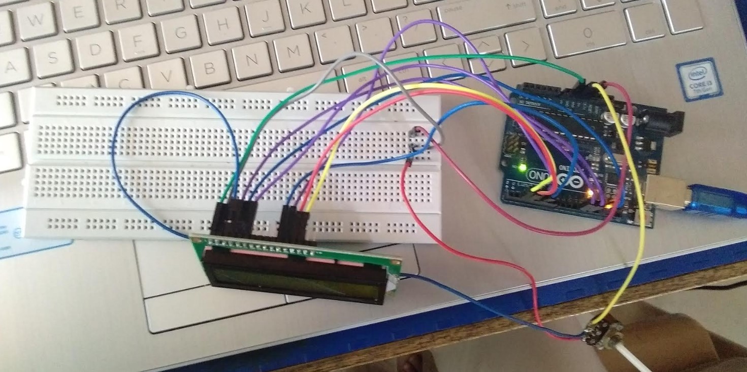
Then I connect LCD display with arudino using jumper wires.
After testing on arduino I go to my atmega board. Then I selected some tool which is required for arduino.and upload the program.
arudino code
here the video
Group Assignment
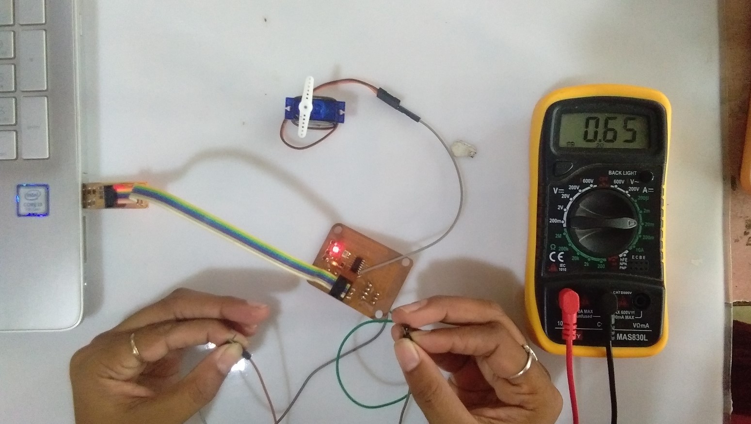
For group assignment, we have to measure the power consumption of the output device.
We have Servo motor and LCD Display we measure the power consumption of LCD and servo motor.
Firstly upload program on board. then a take current checking Multimeter.We join VCC and GND to multimeter
power consumption for servo is 0.64
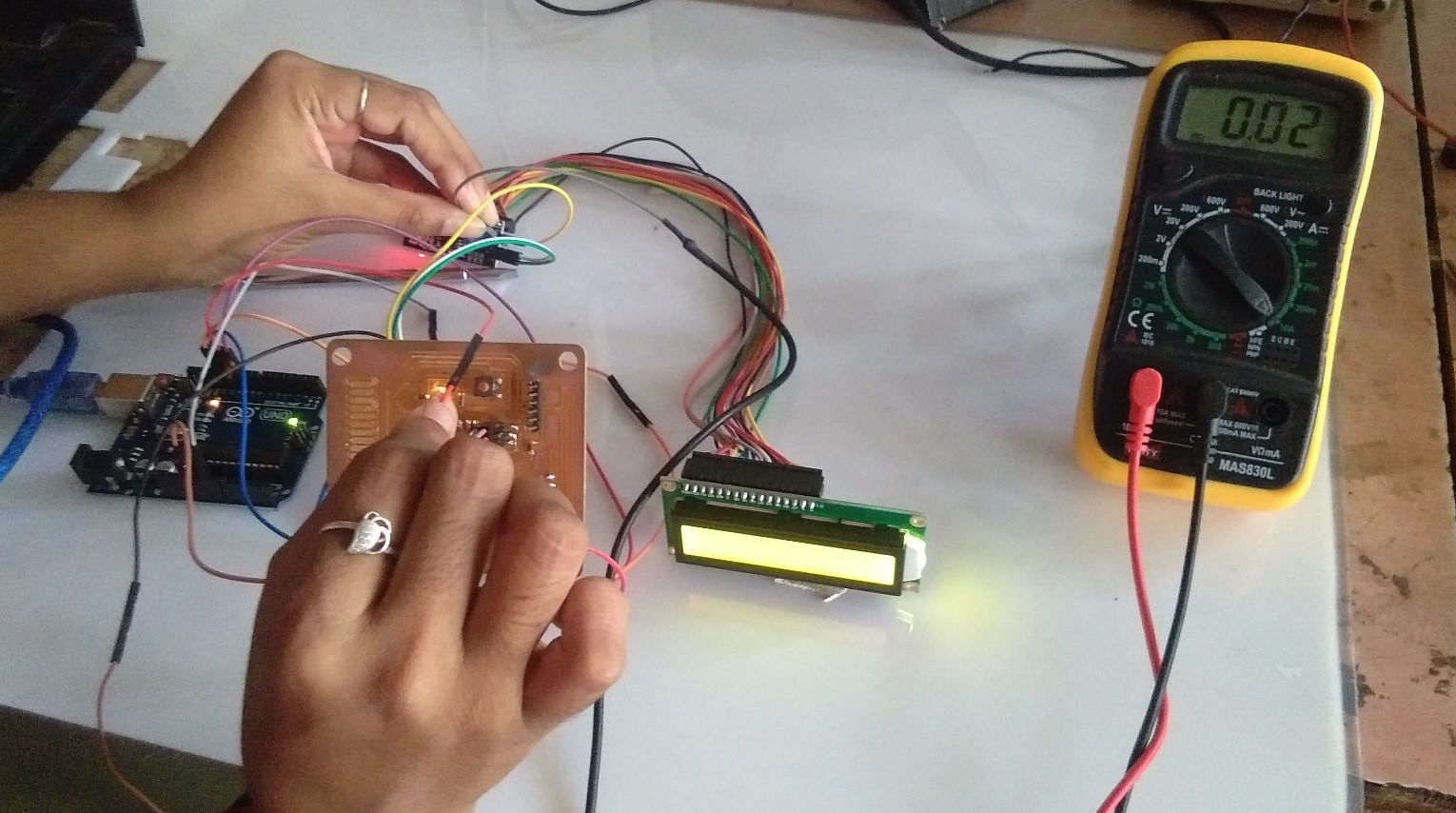
Same thing we done with LCD Display.
we check the power consumption and result is 0.02
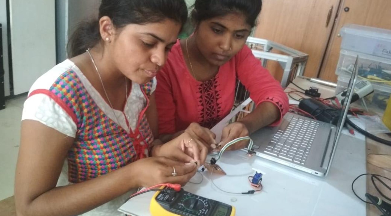
Aditi and me completed this group assignment
You can Download Board file
You can Download PNG File
You can Download .rml file
Learning Outcome
In this week I tried to used LCD Display as a output and adding components and redesign my In my Atmega 328p