8. Computer controlled machining
Assignments for the week
Group assignments
- Test runout, alignment, speeds, feeds, and toolpaths for your machine
Individual assignment
- Make something big on a CNC machine.
Requirements
-
Explained how you made your files for machining (2D or 3D)
-
Shown how you made something BIG (setting up the machine, using fixings, testing joints, adjusting feeds and speeds, depth of cut etc)
-
Described problems and how you fixed them
-
Included your design files and ‘hero shot’ photos of final object
Group assignments
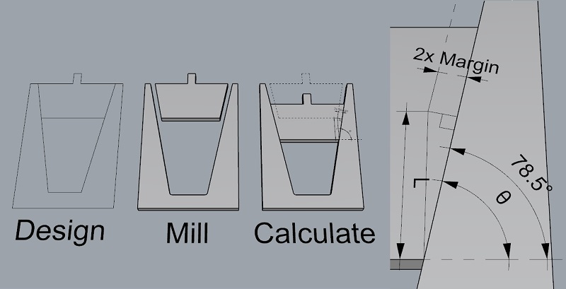
Draw a test patterm
We draw a “Popsicle” shape to test and search a good margin setting.
When the outcomes getting bigger or smaller,
the edge of Popsicle will move up or down with a 1/cosin(θ) magnificator of the design angle. This file gives 10x magnification. (link for file at the bottom of page)
Test cut
updated 6.20.2019
Machine and materials
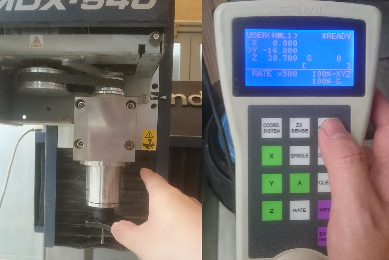
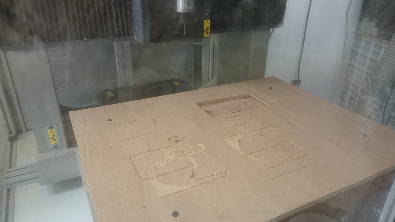
I use 3-axis Roland MDX-540 to do milling. Link
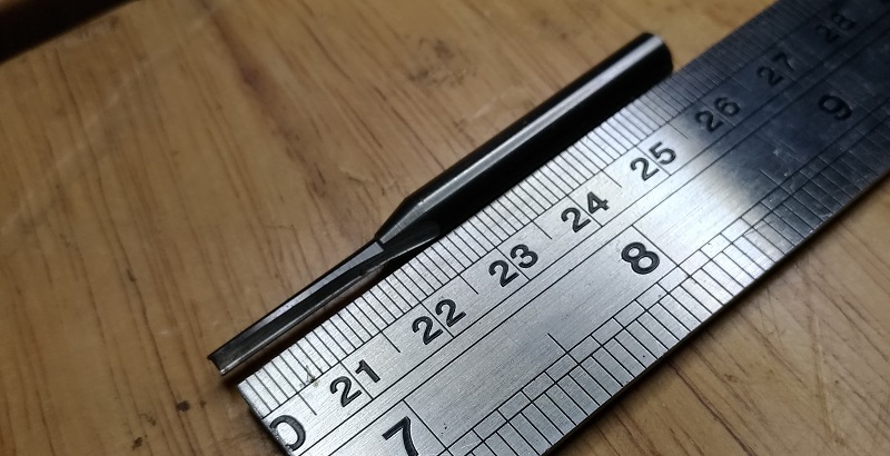
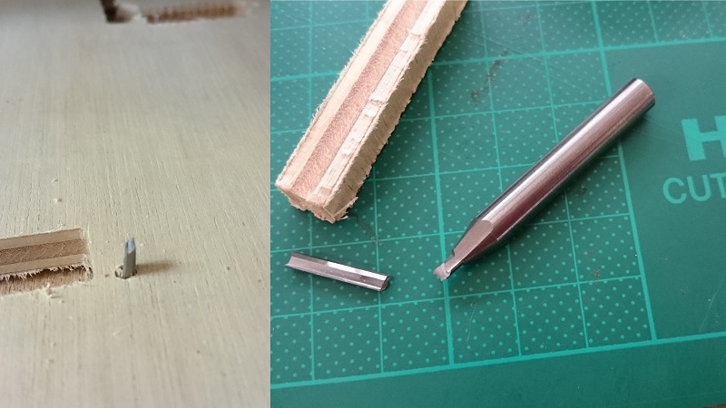
Milling bit is a 3mm cutting diameter, 20mm cutting length 2 flutes, flat end, up-cut, uncoating large angle bit.
It is a bit design and sales by local hobbyist.
Material I use is 8mm lumber core board.
Note: MDX-540 uset user’s XY as working XY, confuse with system XY will cause wrong positioning.
The bit:
Test milling
-
Install the end mill, power on the machine, set up originnal pint of user XYZ.
-
Open Dr.engrave, draw a small Rectangle, move to a desire position.
-
Set a higher position z axis to cut in the air.
-
Set up the “printer” MDX-540, print to makesure the path doed not hit something.
-
Mill It.
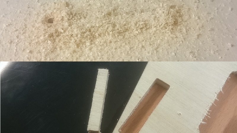
Broken end mill cartige
We try another setting, and break the end mill.
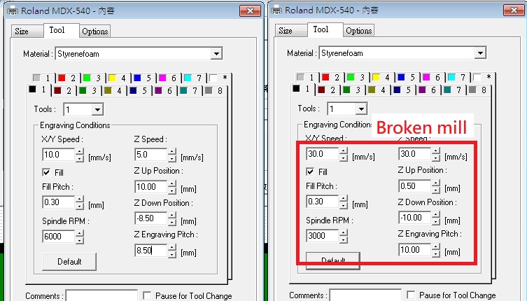
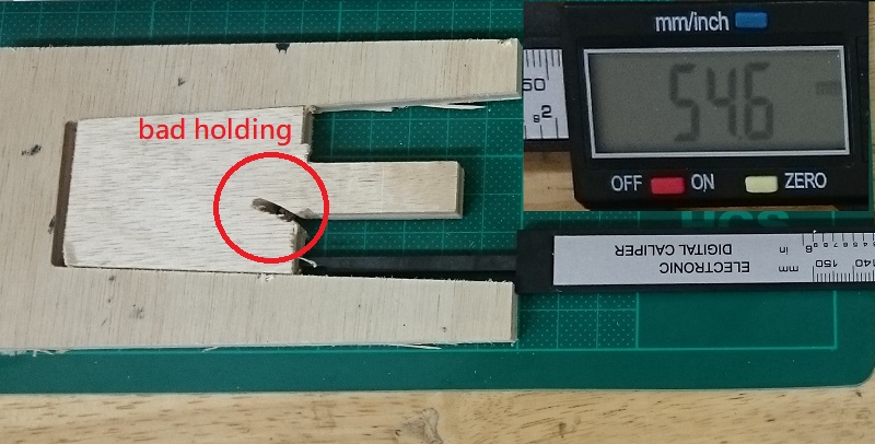
Test Resault
NOTE: This test is a wrong design and calculate but a good estimate.
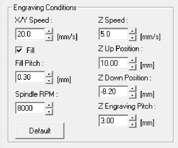
Finally we find a opperatable set up:
Spining speed 10000 RPM,
XY-milling speed 40 mm/min,
Z-milling speed 5 mm/min,
Cutting deepth 3mm.
And Margin is between 54.6 (lightly touch) to 58 (press apply)
So the Margin range for design well be 2.73 to 2.9 mm (1.365 to 1.45 for each side).
I choose 2.75, but the resault shows tighter well be better if you do some after-mill works.
Individual assignment
A too big to build in time project
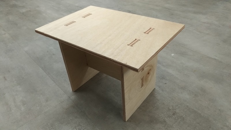
My frist project was a 70 x 135 cm coffee table made by MDX-540 (cutting size 50 x 40 cm)
But It needs too much time to cut and assembly, so after a model had made, I turn to another simplified work.
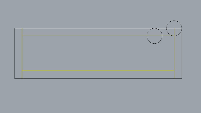
This is my way to graw a pin in 2D sketch.
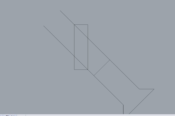
And joint.
Two point in the diagram are the same position when assembly with one of two object turn vertical.
A test model for coffee table.
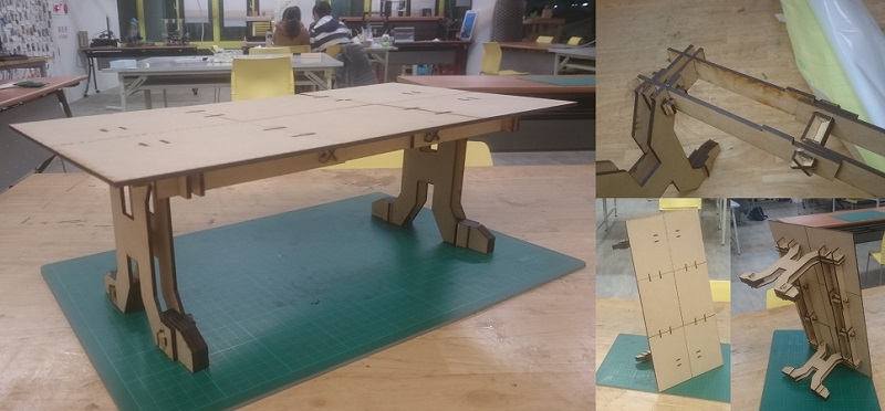
Smaller big thing
Design
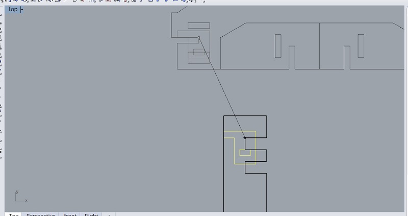
Frist draw a 2D sketch, “grow” a thickness, then assambly to 3D model for test.
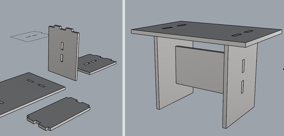
Back to 2D, modify it by the margin measuer in the group assignment.
Arranging for milling
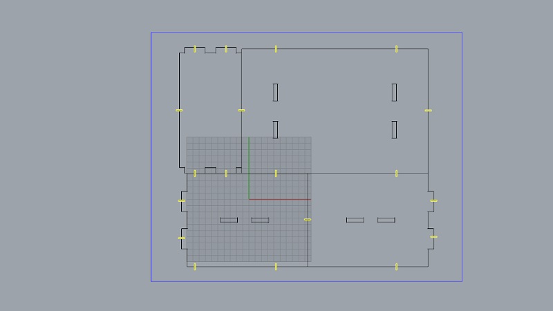
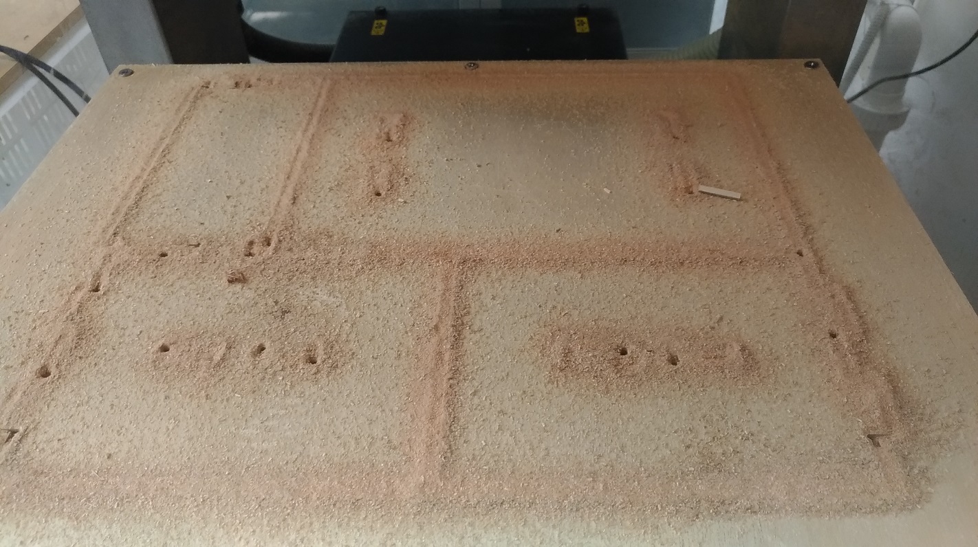
Cut
Milling setting
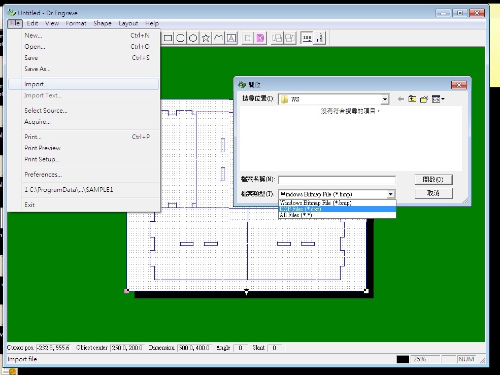
Export DXF file anf import it to Dr.engrave.
Cut air frist, then mill it.
Assambly