7. Electronics design
Assignments for the week
Group assignments
- Use the test equipment in your lab to observe the operation of a microcontroller circuit board.
Individual assignment
- Redraw the echo hello-world board, add (at least) a button and LED (with current-limiting resistor), check the design rules, make it, test it.
- Extra credit: Simulate its operation. Render it.
Requirements
- Shown your process using words/images/screenshots.
- Explained problems and how you fixed them, including how you worked with design rules for milling (DRC in EagleCad and KiCad).
- Outlined problems and how you fixed them.
- Included original design files (Eagle, KiCad, Inkscape, .cad - whatever).
Group assignments
See 2019 Fablab Taipei Group site Week 7
Individual assignment
BOM
| Parts | Spec. | Quantity |
|---|---|---|
| ATtiny 44A | 1 | |
| Resistor | 0 ohm | 1 |
| 100 ohm | 2 | |
| 10k ohm | 2 | |
| Crystal | 20 MHz | 1 |
| Capacitor | 0.1 nF | 2 |
| 100nF | 1 | |
| LED | Red | 1 |
| Yellow | 1 | |
| Bottom | 1 | |
| Heder | 2x3 | 1 |
| 1x6 | 1 |
Redraw and check the design rules.
-
Download and install Eagle. Download free version

-
If needed, change the language by command line or .bat file, and use it as a shortcut.
cd <path of eagle>
    SET LANG=en_US
    start eagle.exe
-
Download and unzip Fab academy libraries. Download libraries here
-
Open Eagle, load library at file / open / Library.

-
Save it then close it.

-
Create a new project then a new schematic.

-
Check Datasheet to replace by crystal. It shows reccommended capacitor as well.
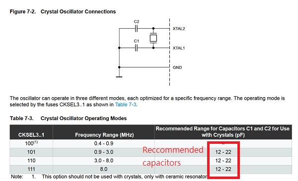
-
Add parts, duble click to palce it, Esc to finish.

-
Link parts.

-
Draw a open end then name it to link with those have the same name.

-
Right click to set values of parts.

-
Swich to board view

-
Set up Design rules frist. Otherwise you will need to draw all path again.

-
Move and rotate to arrange parts.

-
Route parts. Don’t use auto route, It only works when you need a hint.

-
Check Errors

Make it
-
Show only top layer and export image.


-
Use document layer, same to set and export the outline.

-
Go to your images and set (or check) the right size by image editer.

-
If you have a wrong size…

-
Mill it, soldering it, same as week 5 (or open in a new tab)

Test it
After downgrade Arduino IDE to 1.6.9.0, I can programing attiny 45 borad. But when I programming attiny 44a, the IDE returns an error.
avrdude: stk500_getsync() attempt 1 of 10: not in sync: resp=0x15
avrdude: stk500_getsync() attempt 2 of 10: not in sync: resp=0x15
avrdude: stk500_getparm(): (a) protocol error, expect=0x14, resp=0x14
avrdude: stk500_getparm(): (a) protocol error, expect=0x14, resp=0x01
avrdude: stk500_initialize(): (a) protocol error, expect=0x14, resp=0x10
avrdude: initialization failed, rc=-1
Double check connections and try again, or use -F to overridethis check.
Try it again
avrdude: Expected signature for ATtiny44 is 1E 92 07
Double check chip, or use -F to override this check.
After change two capacitor that with cystal to 10 pF, and remove external clock, I guess it’s a soldering issue.
I will make another board to test.
A new board works fine.
Code
Following is the code for Arduino IDE.
int blink_time = 500;

void setup() {
  // initialize digital pin 13 as an output.
  pinMode(2, INPUT);
  pinMode(3, OUTPUT);
}

// the loop function runs over and over again forever
void loop() {
  if (digitalRead(2)==HIGH){
    blink_time=1000;
  }
  else if ((digitalRead(2)==LOW)){
    blink_time=300;
  }
  else {
    blink_time=500;
  }

  digitalWrite(3, HIGH);   // turn the LED on (HIGH is the voltage level)
  delay(blink_time);              // wait for a second
  digitalWrite(3, LOW);    // turn the LED off by making the voltage LOW
  delay(blink_time);              // wait for a second
}