Since my Final project deal with the controlling and monitoring the temperature and the humidity inside the infant incubator, in this assignment I decided to work on temperature sensor as an input to to the microcontroller.
Basically, microcontroller accepts two types of inputs depending up on the type of sensor i.e. analog or digital. Analog sensor senses the external parameters (wind speed, solar radiation, light intensity etc.) and gives analog voltage as an output. The output voltage may be in the range of 0 to 5V. There are a wide variety of temperature sensors compatible with Arduino, ESP32, ESP8266 and other development boards. So, it can be difficult to to pick up the most suitable sensor for your project. To overcome this problem, I compared the results from six different sensors: DHT11, DHT22, LM35, DS18B20, BME280 and SHT11.
Group assignment
Analog input
Probe an input device’s analog levels and digital signals
To measure the input signals We used the memory prime oscilloscope available in our FABLAB.
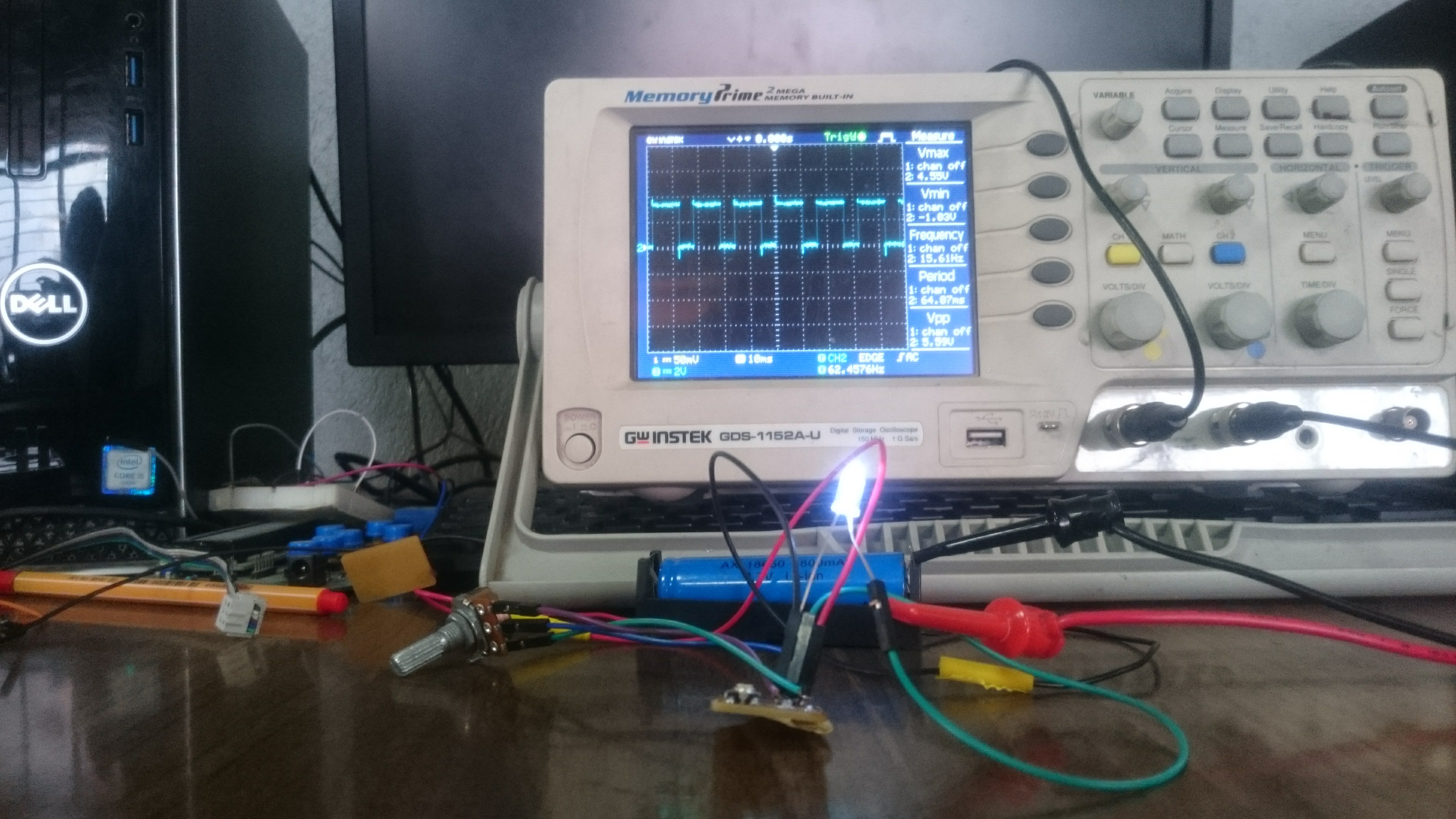
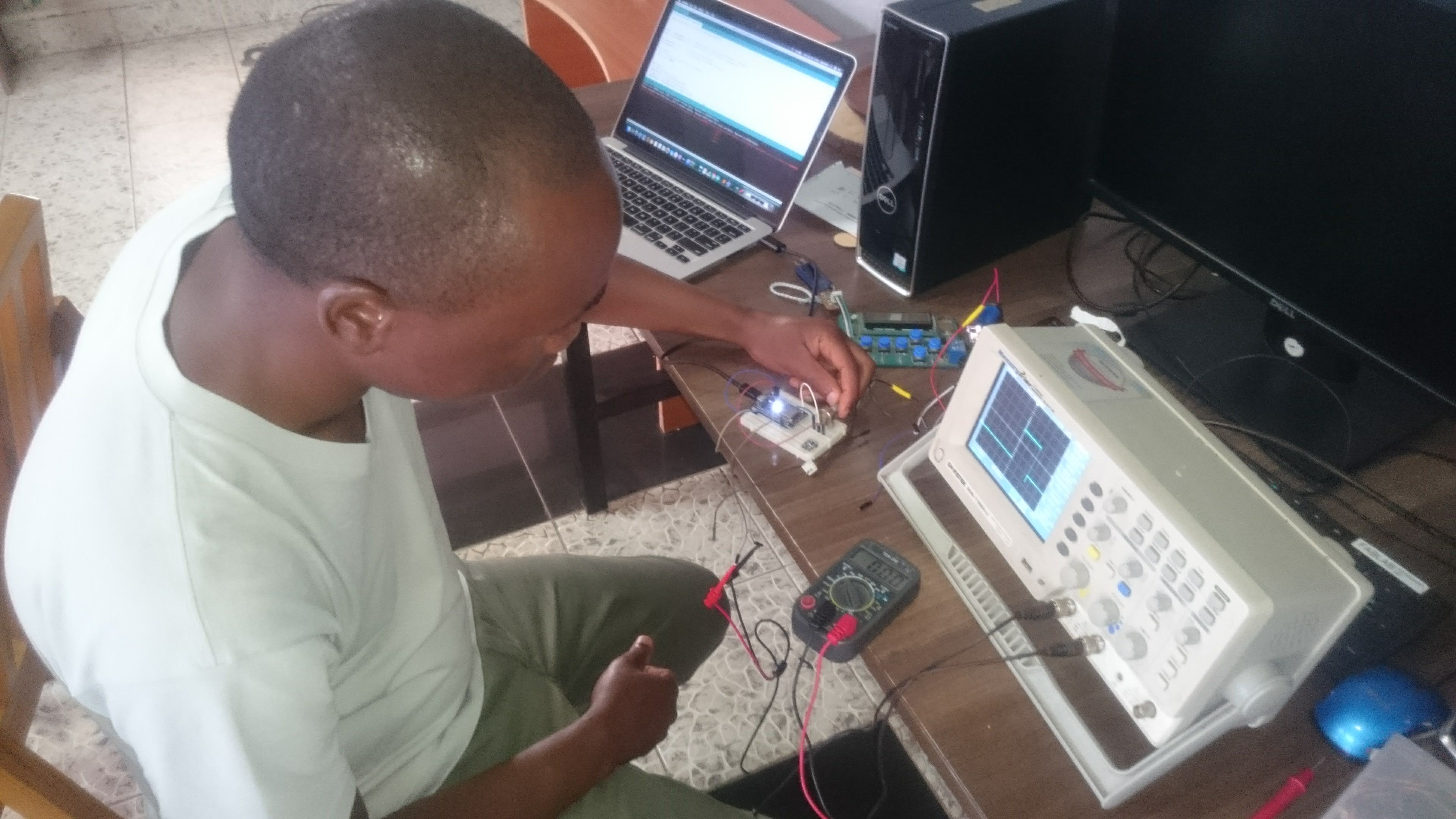
We used Attiny45 and potentiometer as the input device. Attiny45 has only two analog input pins (AIN1 and AIN2), our potentiometer was connected to AIN1 pin
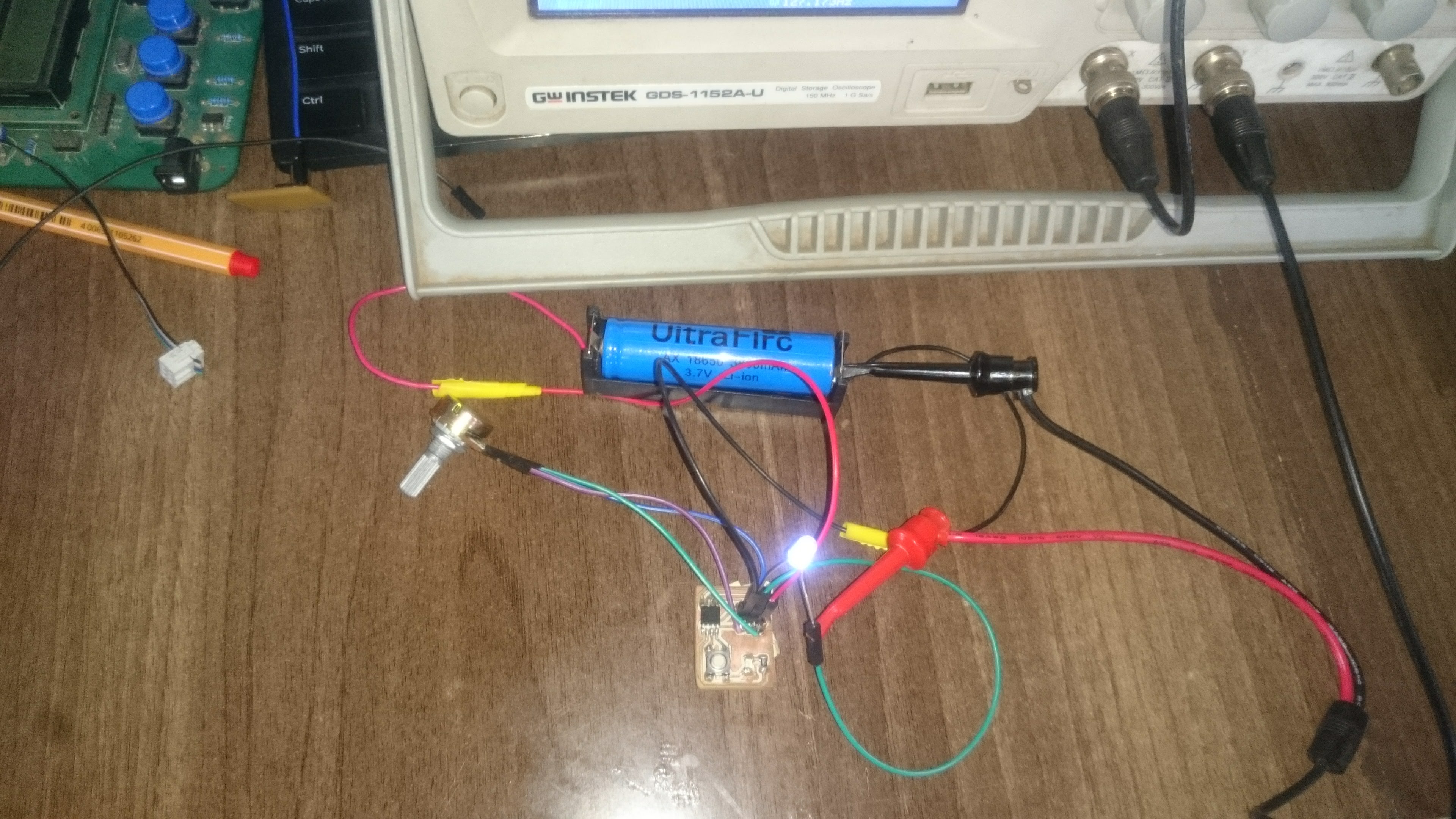
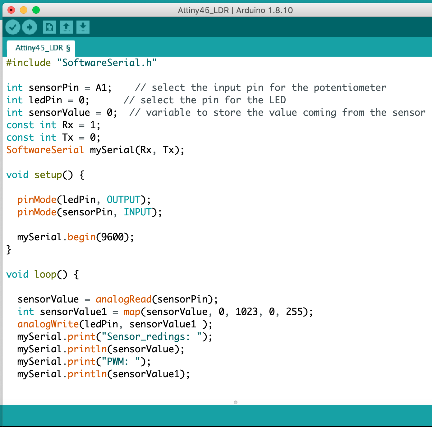
By adjusting the potentiometer the input voltage was varying between 0 and 3.98 voltage.
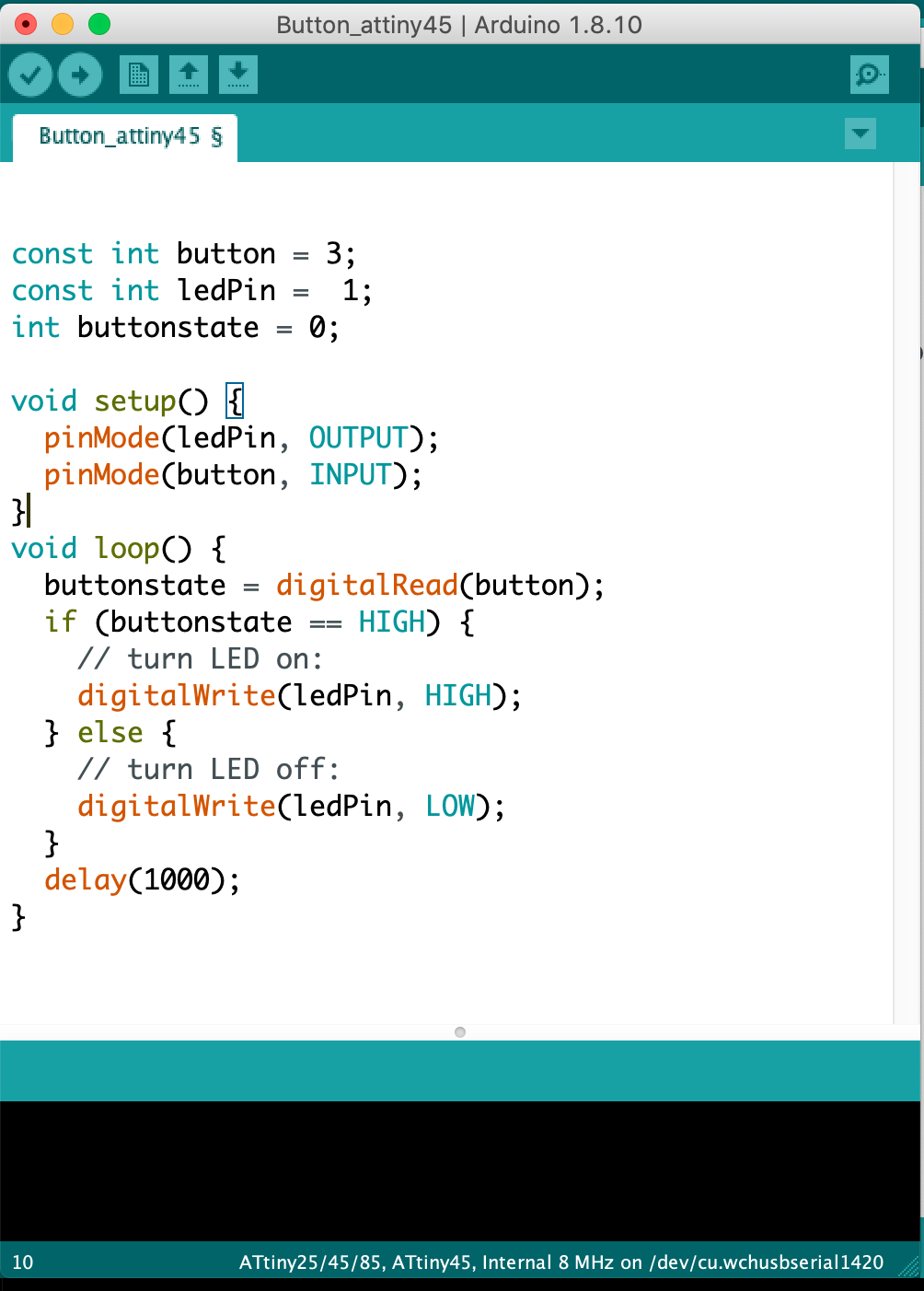
Digital input signal
Analog input with nodemcu
We also measured the input signal by using ESP12 NODEMCU Board and serial ploter from arduino IDE
Individual assignment
Measure something. add a sensor to a microcontroller board that you have designed and read it.
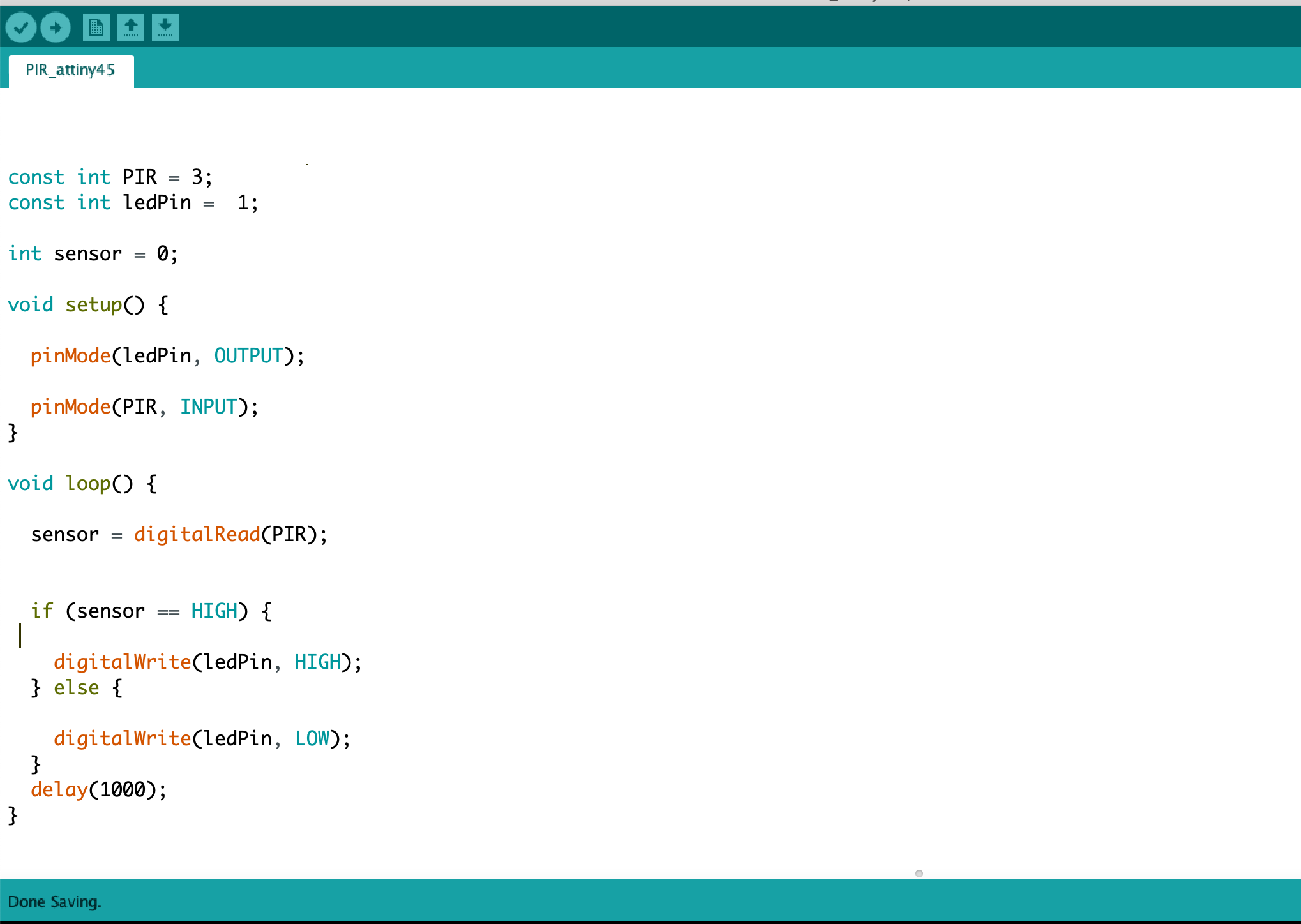
In this assignment, I decided to design a security system for detecting the presence of the intruder in the vicinity of the compound or inside the building
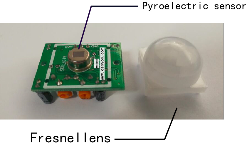
What is a PIR Sensor?
PIR sensor detects a human being moving around within approximately 10m from the sensor. This is an average value, as the actual detection range is between 5m and 12m.PIR are fundamentally made of a pyro electric sensor, which can detect levels of infrared radiation. For numerous essential projects or items that need to discover when an individual has left or entered the area. PIR sensors are incredible, they are flat control and minimal effort, have a wide lens range, and are simple to interface with.
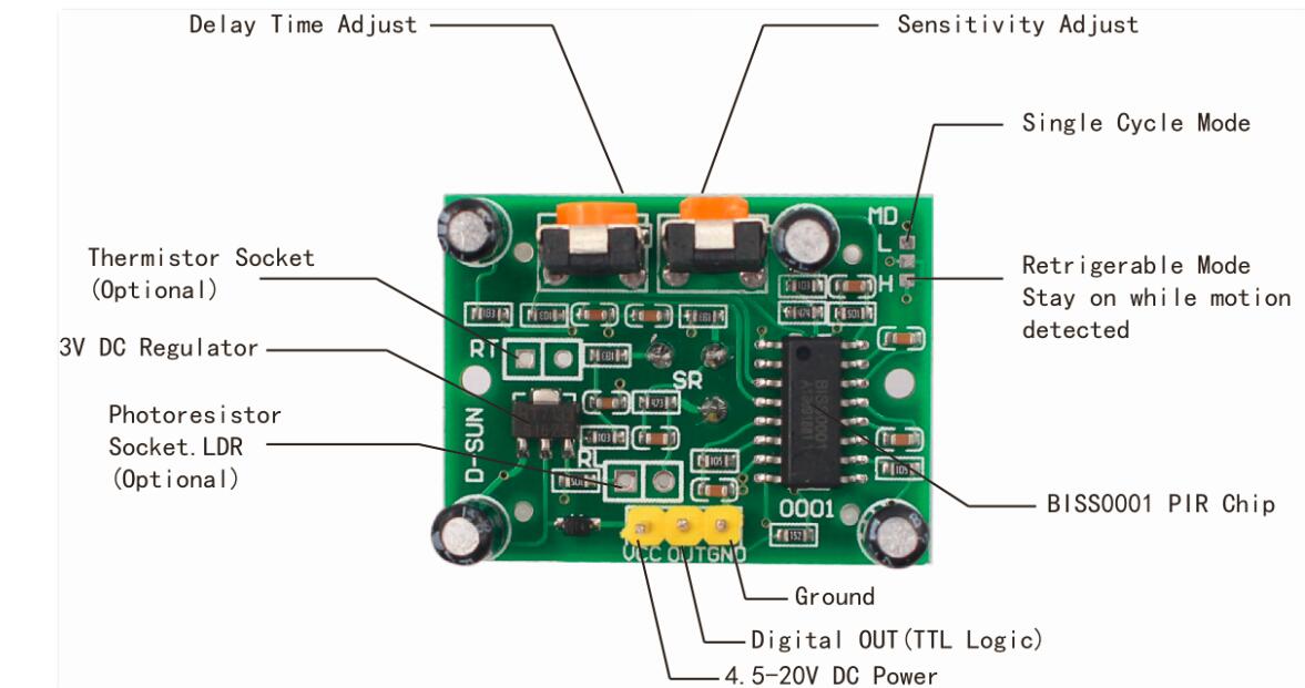
SPECIFICATIONS
- Working voltage: 4.5V to 20V
- Output: High: 3.3V, Low: 0V
- Detection angle: Approximately 120 degrees
- Range: Adjustable, up to 7m
- Trigger modes: L unrepeatable trigger / H repeatable trigger (default)
- Dwell time: (Stay-ON time) adjustable between 5-300 Seconds. –– it can be further increased by increasing the value of the CY1-Timing capacitor on pin 4 of the IC
- Operating Temperature: -20 – +80 Degrees C.
- PCB Dimensions: 33x25mm, 14mm High not including the Lens; Lens: 11mm high, 23mmDiameter. Weight: 6g
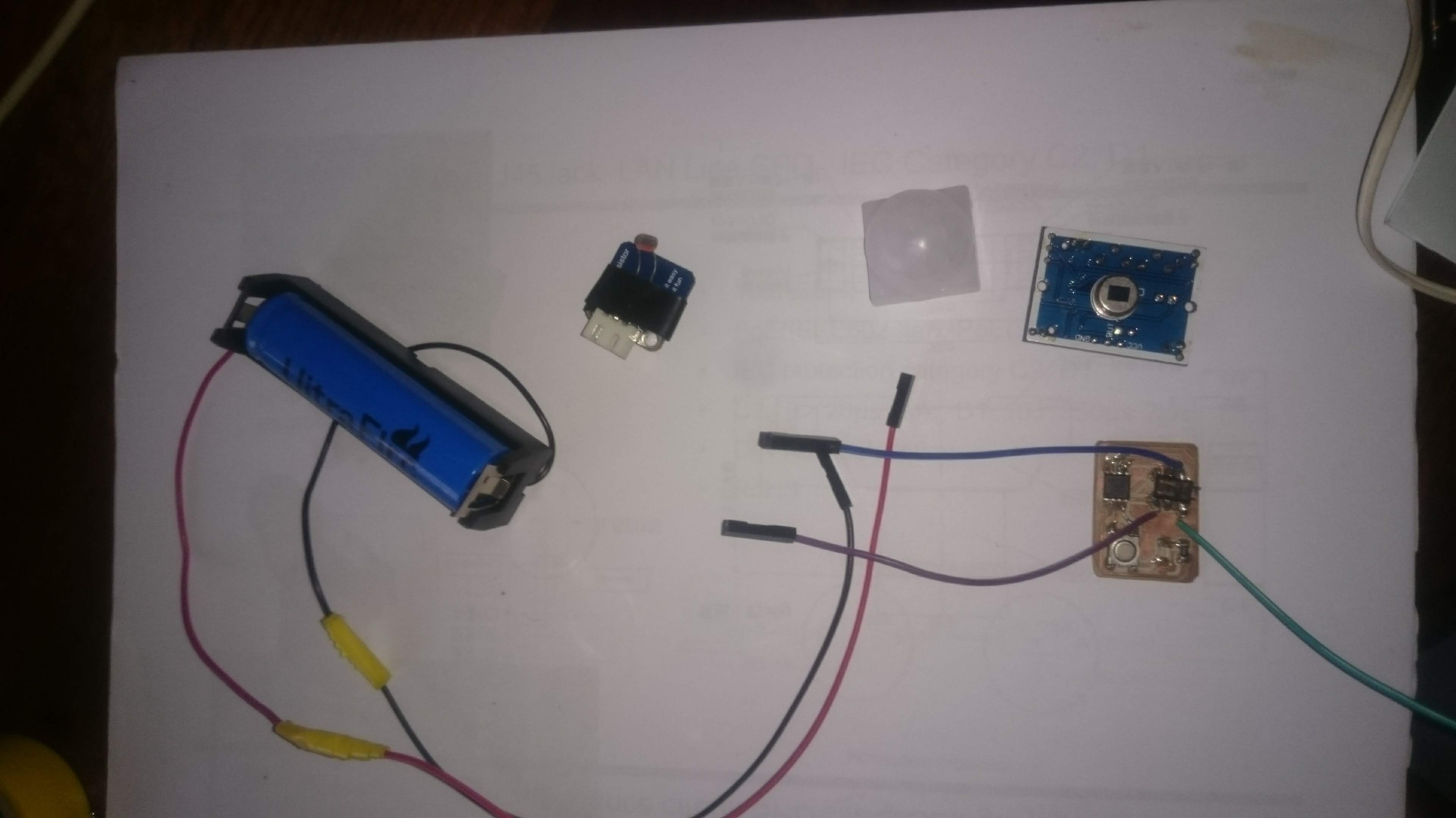
IMPLEMENTATION
Used materials:
- PIR sensor
- Attiny45
- 3.7 volts lithium battery
- FabTinyISP board
- Buzzer sound
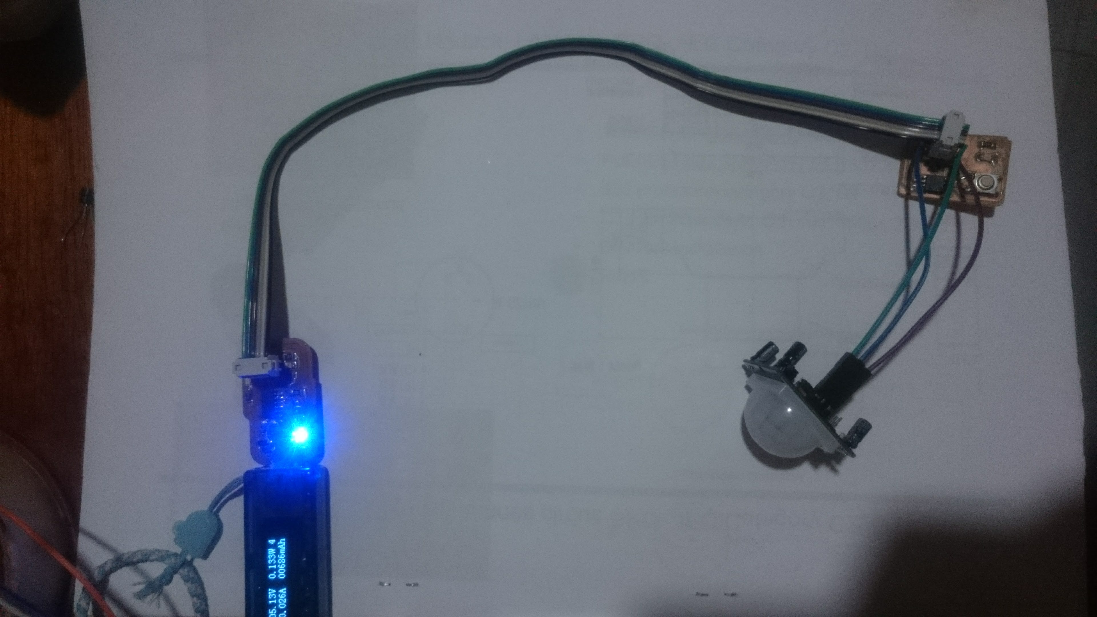
To implement the circuit, I prefered to use the Attiny 45 board designed during the ELECTRONICS DESIGN assignment week. more details.
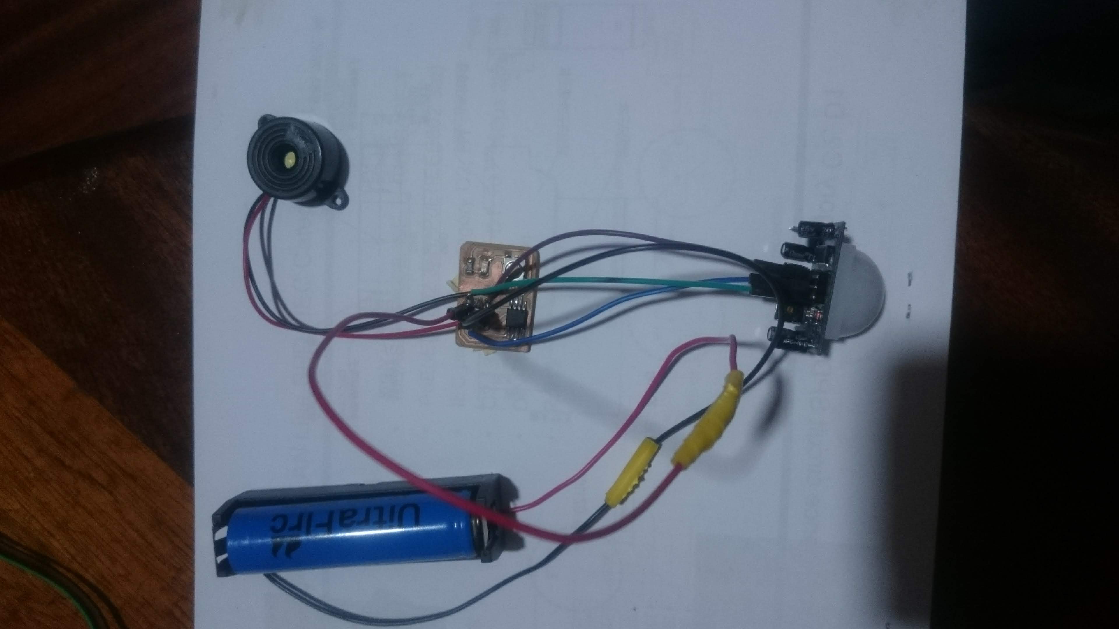
programming the board with FabTinyISP board
Most of the used sensors are digital sensors and use onewire as the communication protocol except LM35 which is the analog sensor.
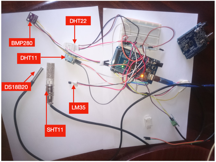
To compare sensors, I preferred to use Atmega 2560 (Arduino mega), because this board has many pins and high performance. After consulting the data-sheet of the ATmega2560, I wired the data pins of the temperature sensors to the following pins on Arduino Mega:
- DHT11: Pin 2
- DHT22: Pin 5
- DS18B20: Pin 4
- LM35: Pin A0 (analog PIN)
- SHT11: Pin 11 (Data), Pin 10 (SCK)
- BMP280: Pin 20 (SDA) and Pin 21 (CSL)
Arduino mega with sensors
Reading Sensors with Python
To capture the data I used the python script that help me to extract the data from Arduino mega through the USB port.
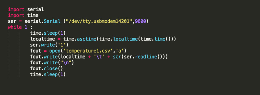
The experiment run for approximately 7 hours and temperature readings were recorded every 5 seconds.
Sample of the recorded data

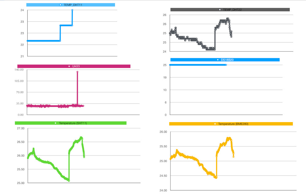
We’ve plotted all readings to better compare the measurements from the different temperature sensors.
Comparing Temperature Readings
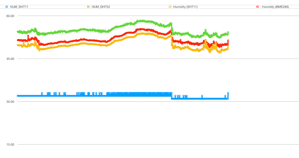
Comparing Humidity Readings
The obtained results show that BME280 and SHT11 are also the temperature sensor that gave more stable temperature readings without many oscillations between readings. This has to do with the resolution of the sensor. The DHT22 and LM35 behave very similarly with lots of oscillations. The DHT11 couldn’t detect small temperature changes, because its resolution is of 1ºC.
Finally, the LM35 temperature sensor detected has lots of oscillations between measurements. After comparing many sensors from different vendors, I decided to use BME280 because SHT 11 is more expensive comparing to BME 280 but the obtained results is almost the same.
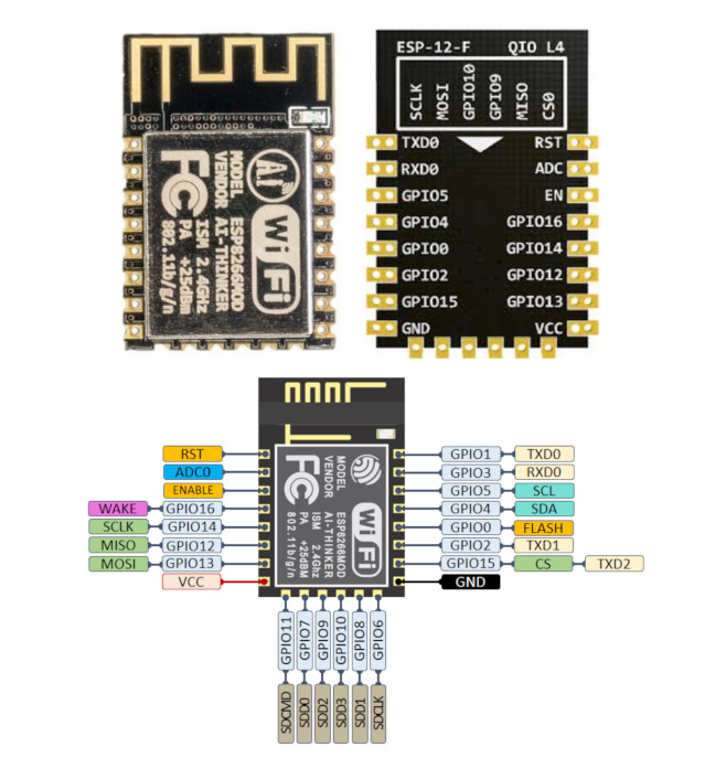
ESP-12E Module
To accomplish this assignment, I decided to use another type of microcontroller ESP-12E, based on ESP8266. This devices has many features comparing to the existing arduino or Attiny44 0r Attiny45 such as a more powerful processor than the Arduino's Atmega328, a 4Mb flash memory and much more RAM. It basically has almost everything that an Uno has to offer, plus much more. It has fewer GPIO, ADC and PWM options than the Uno, but supports Serial Communication protocols which is motivated me and pushed me to work on this board. more details.
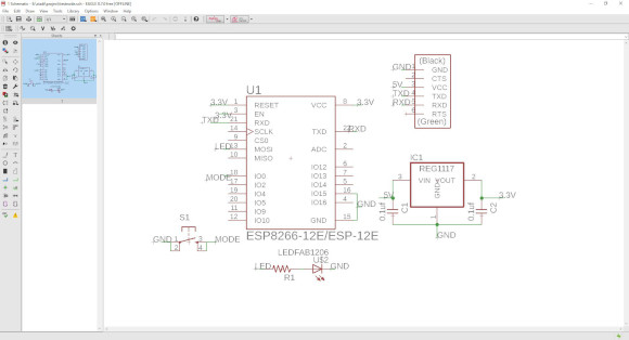
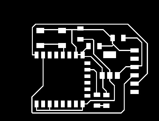
Schematic and circuit board
The circuit was designed with the help of the eagle software.Afterward the circuit board and the PCB board were generated and printed out.
Eagles circuit diagram
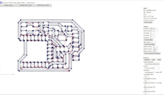
Traces
Creating Milling files with Fab Modules.
Outlines
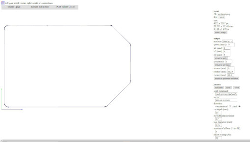
To print PCB I used Roland SRM-20 Desktop Milling Machine.
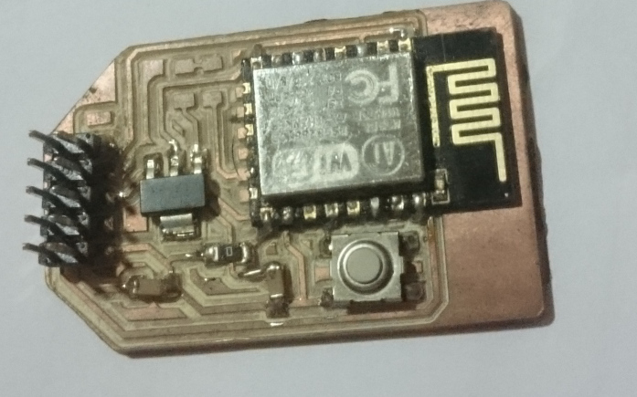
Printed and asssembled board
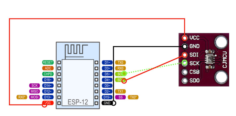
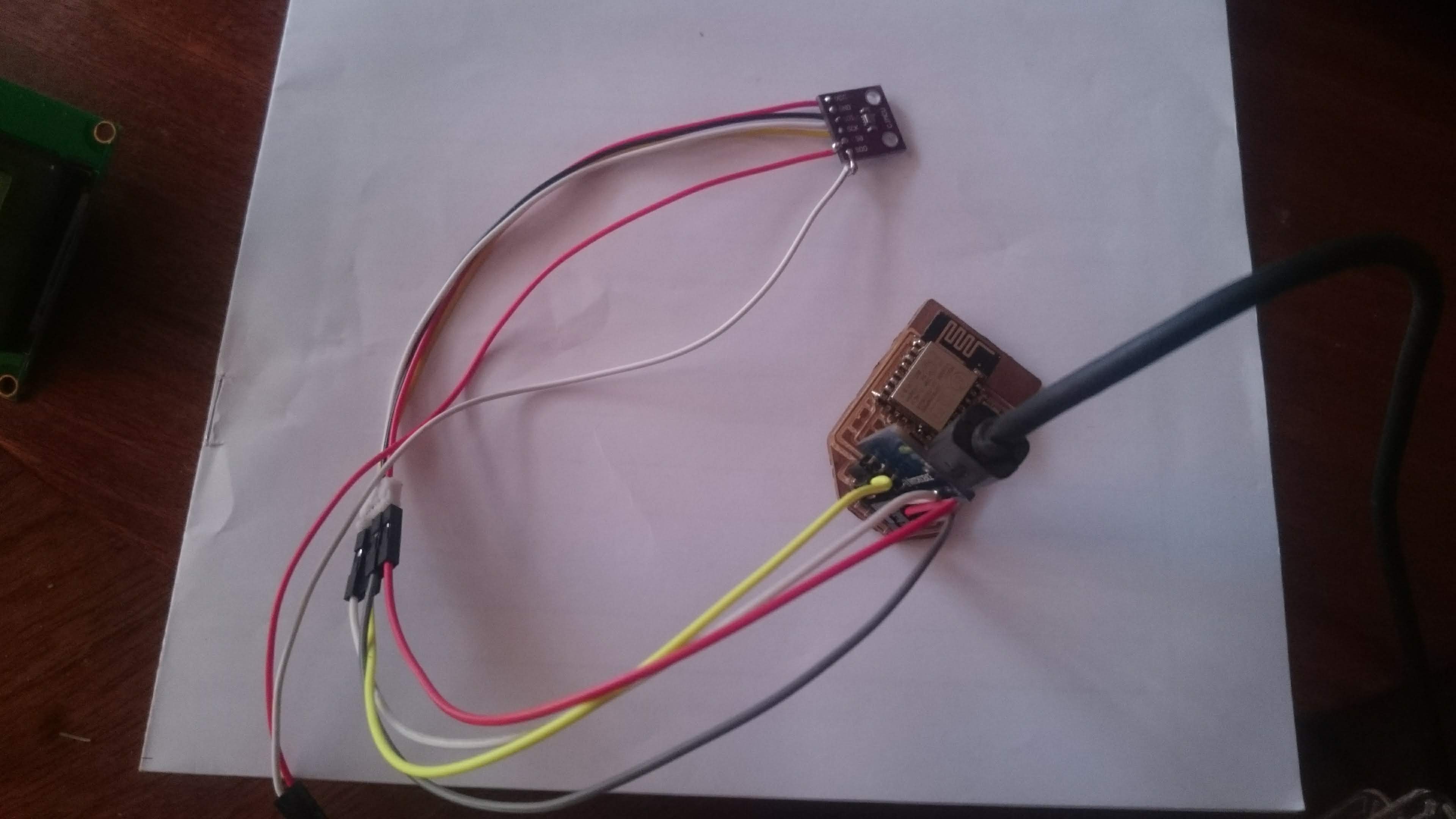
Wiring BME280 Sensor to ESP8266
Connections are fairly simple. Start by connecting VIN pin to the 3.3V output on the ESP8266 NodeMCU and connect GND to ground. Next, Connect the SCL pin to the I2C clock D5 pin on your ESP8266 and connect the SDA pin to the I2C data D4 pin on your ESP8266.
Uploading Code to the ESP8266 12-E Chip
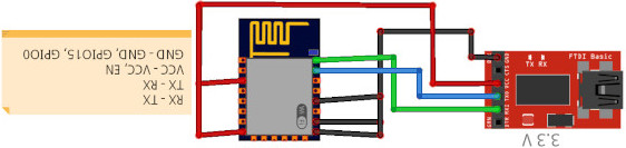
Uploading code to the ESP-12E requires establishing a serial communication between your ESP8266 and an FTDI Programmer as shown in the schematic diagram below.
Connect FTDI VCC to ESP8266 ESP-12E VCC and GPIO_2, RTS/CTS to CH_PD, DTR to GPIO_0, GND to GND and GPIO_15, TX to RX and RX to TX.
Aploading the program to the board
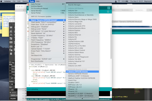
Open the Arduino IDE.In the Arduino IDE, under Tools –> Board, select “Generic ESP8266 Module”.
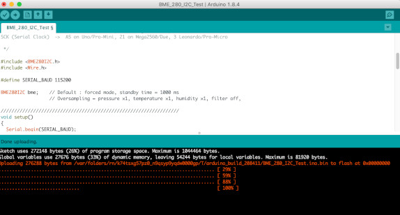
The next step is to upload the program to the board and check if the progress of uploading is displayed in the console of the Arduino IDE.If so, you can now write any sketch you want and program your ESP8266 easily.
If everything goes well, you should get a message like this one
Challenge
When I was aplading the program to the the board, I didn't archieve the result at the first trial.
This is the identified error
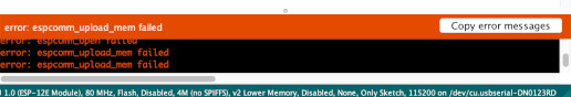
I searched form the internet the meaning of the error and I found the solution from this tutorial on youtube. The GPI0 pin was not connected to the GND.