Inspiration for the project
After observing the transmittion of the Noval COVID-19 and how its mortallity rate increased daily, I thought if I make a sanitizing tunnel might help to reduce the transmission of the COVID-19.
Project implementation
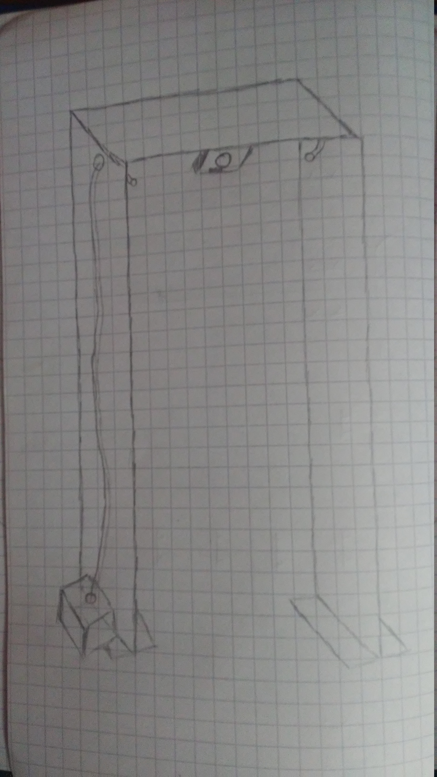
I started with sketching the final look of the project.
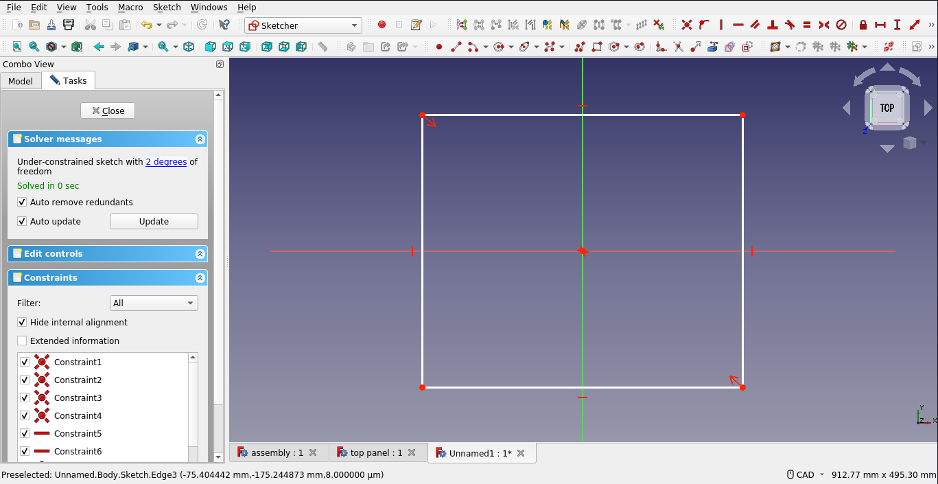
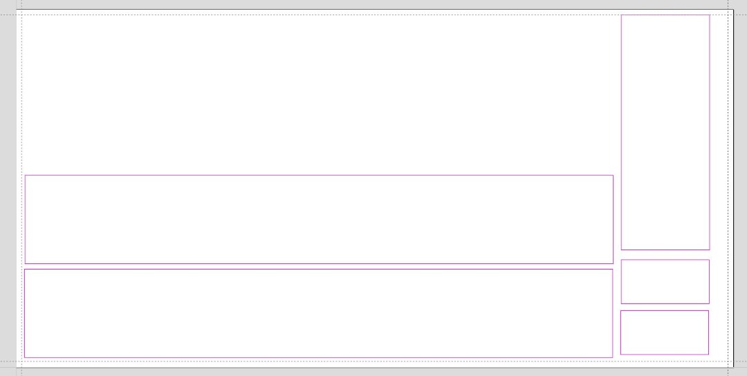
Then I designed the tunnel in FreeCAD, the part I will cutout for implementation.
I made a sketch of the parts I will use to create the tunnel.
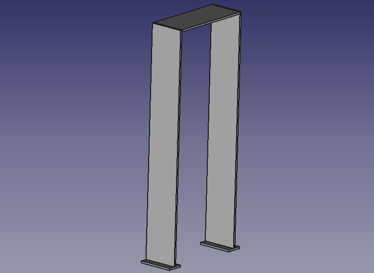
I made an assembly of different parts for visual of the final tunel.
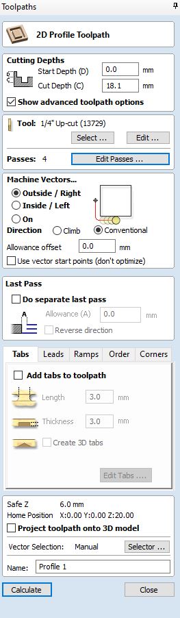
I exported the original files in DXF and used them in Vcarve to cut parts to make the tunnel.
this are the settings I used for toolpath cutting out the pieces.
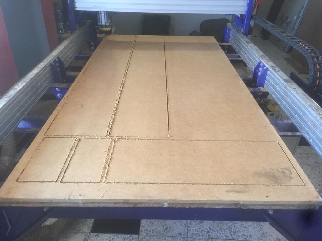
and here after cutting the pieces out.
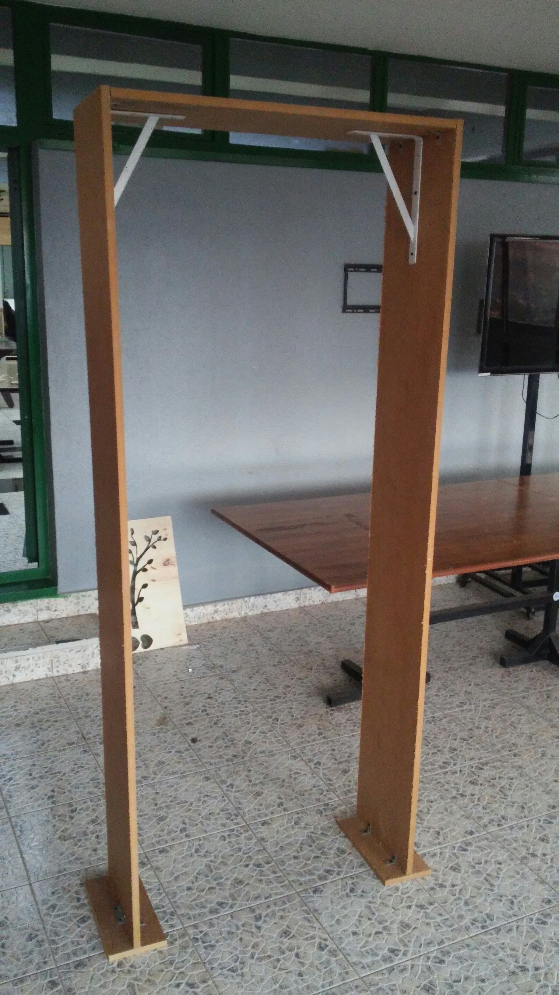
Here is the image of the assembled tunnel.
I continued to make electronics of the system.
Control system
For control system I edited the input devices to add a 12v input and a regulator for 5v out.
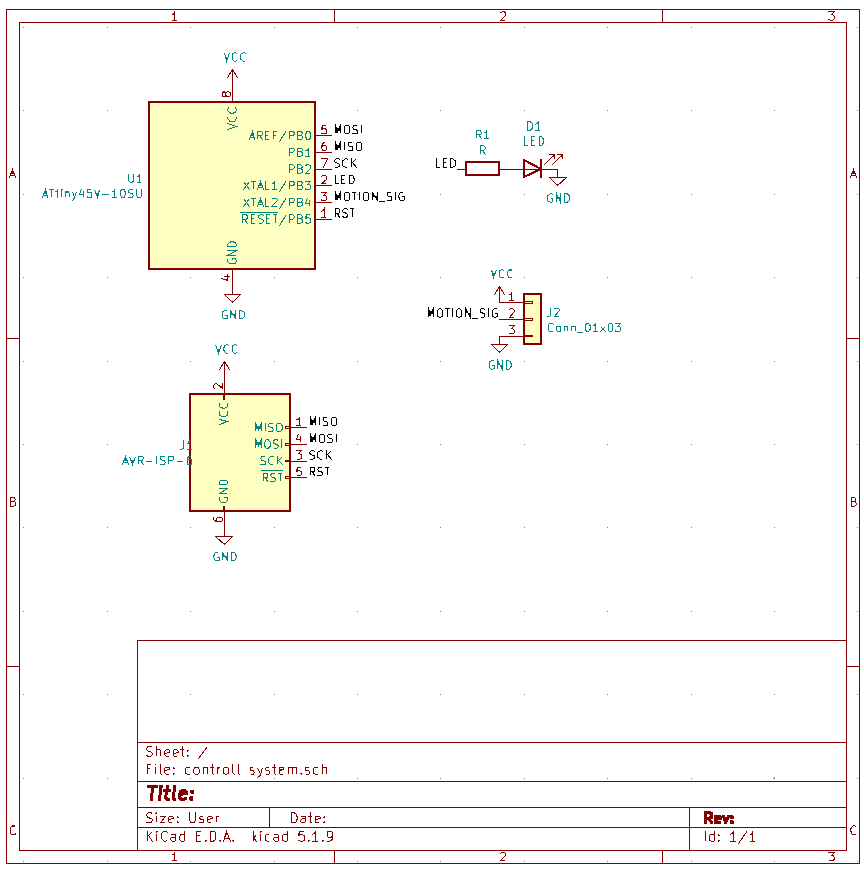
This is the schematic of the input devices assignment and I made some modification in it.
I added a relay for switching ON & OFF the pump and a 5V regulator for supplying the necessary volt for the circuit.
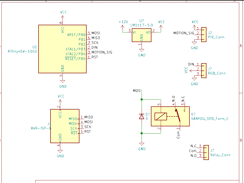
This is the circuit design of the controll system.
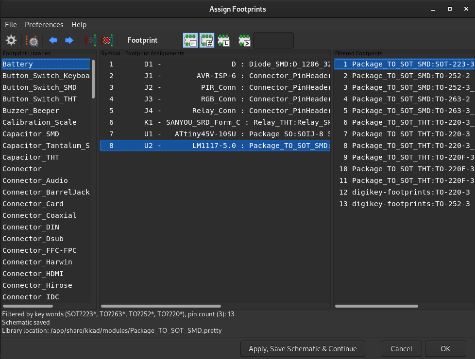
In KiCad after designing a schematic you assign each component with a footprint you will be using in desinging the PCB. Below its an image of the window of assigning components to their footprint.
I moved on to import component's footprint to wire its PCB traces.
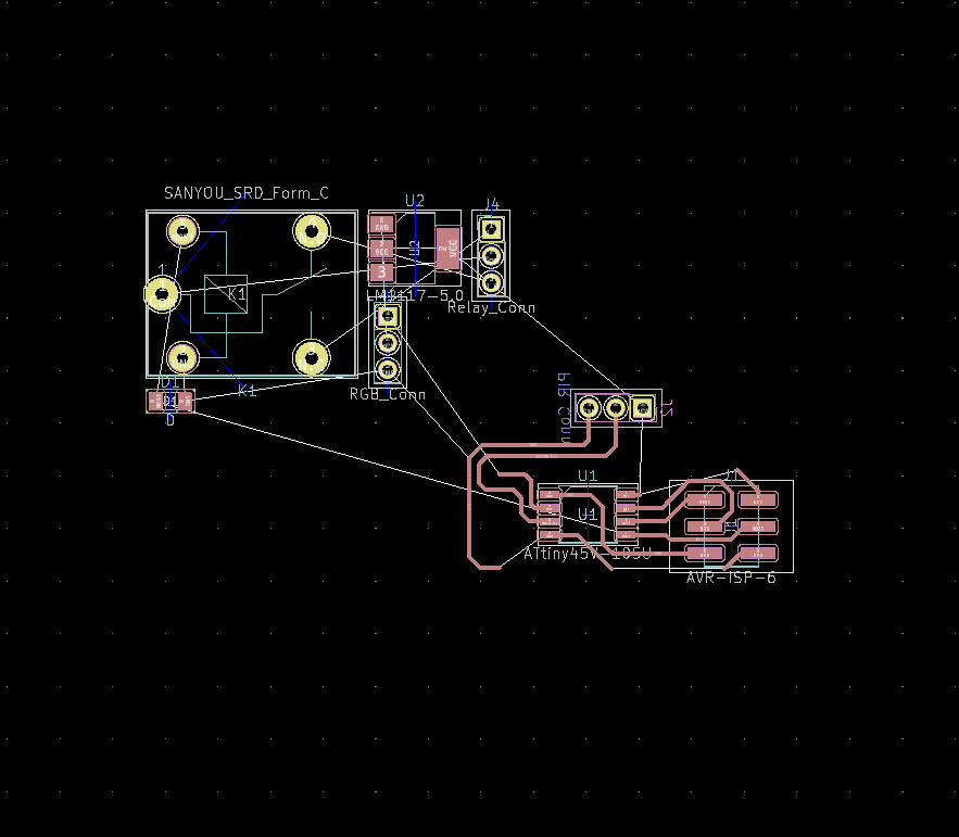
I placed components in their place and wired its traces.
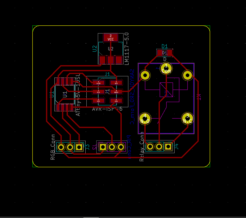
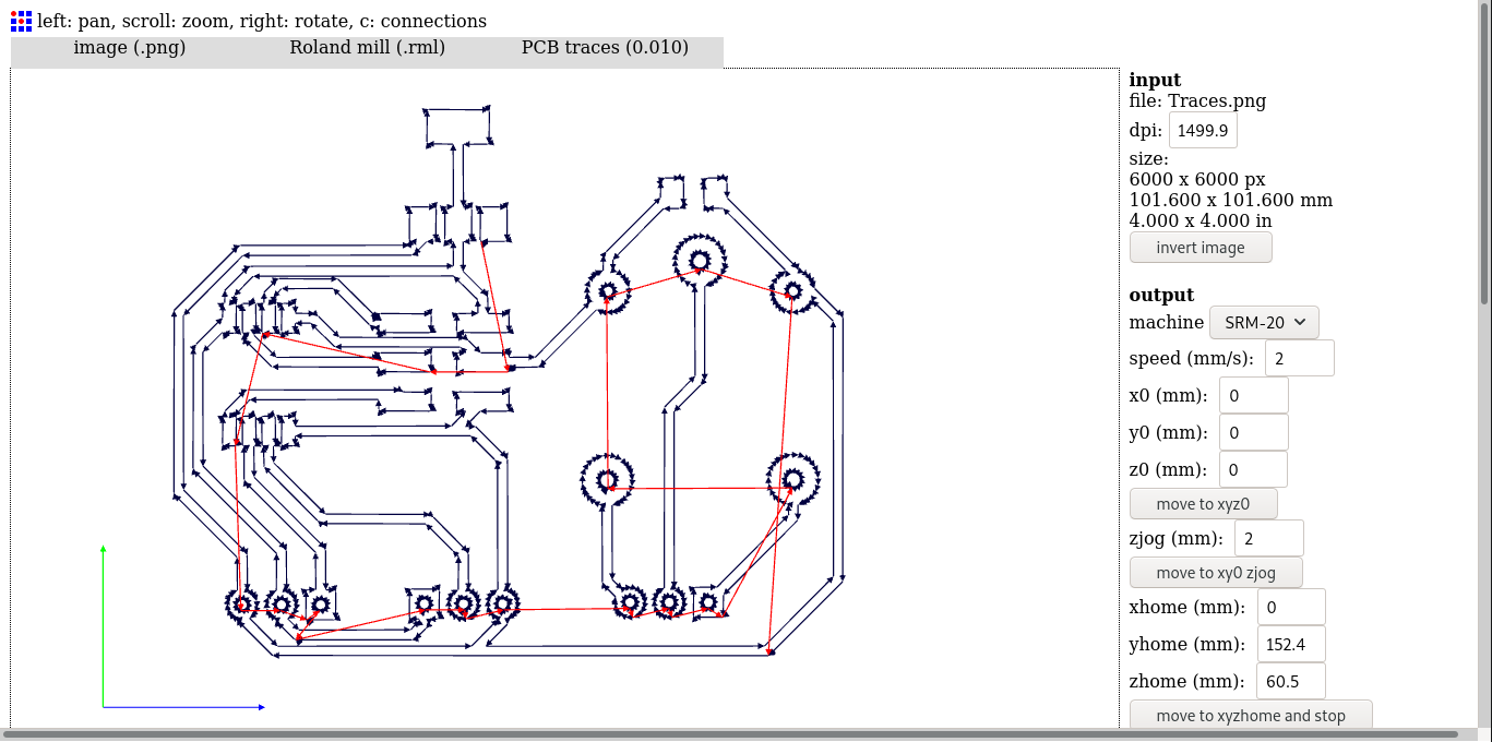
I exported the design files in SVG format which I will use on Fabmodules to generate machine path.
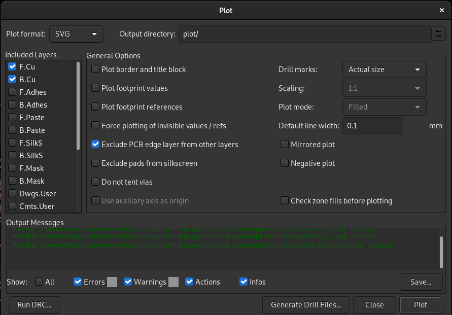
I used Fabmodules to generate machine file to mill the PCB.
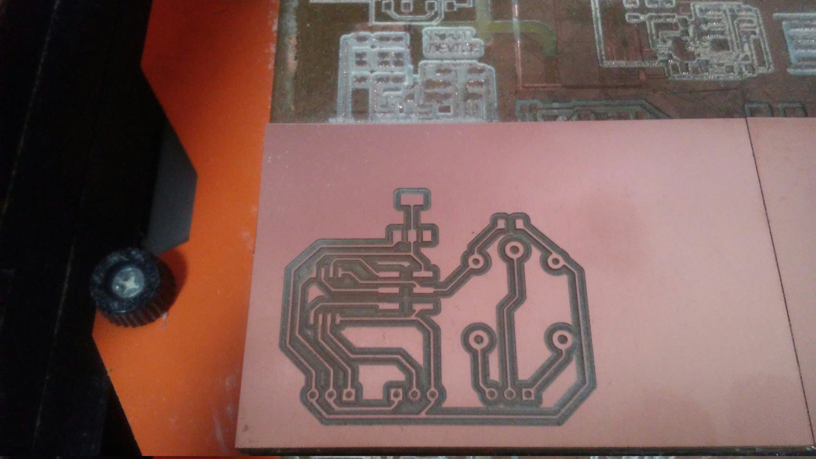
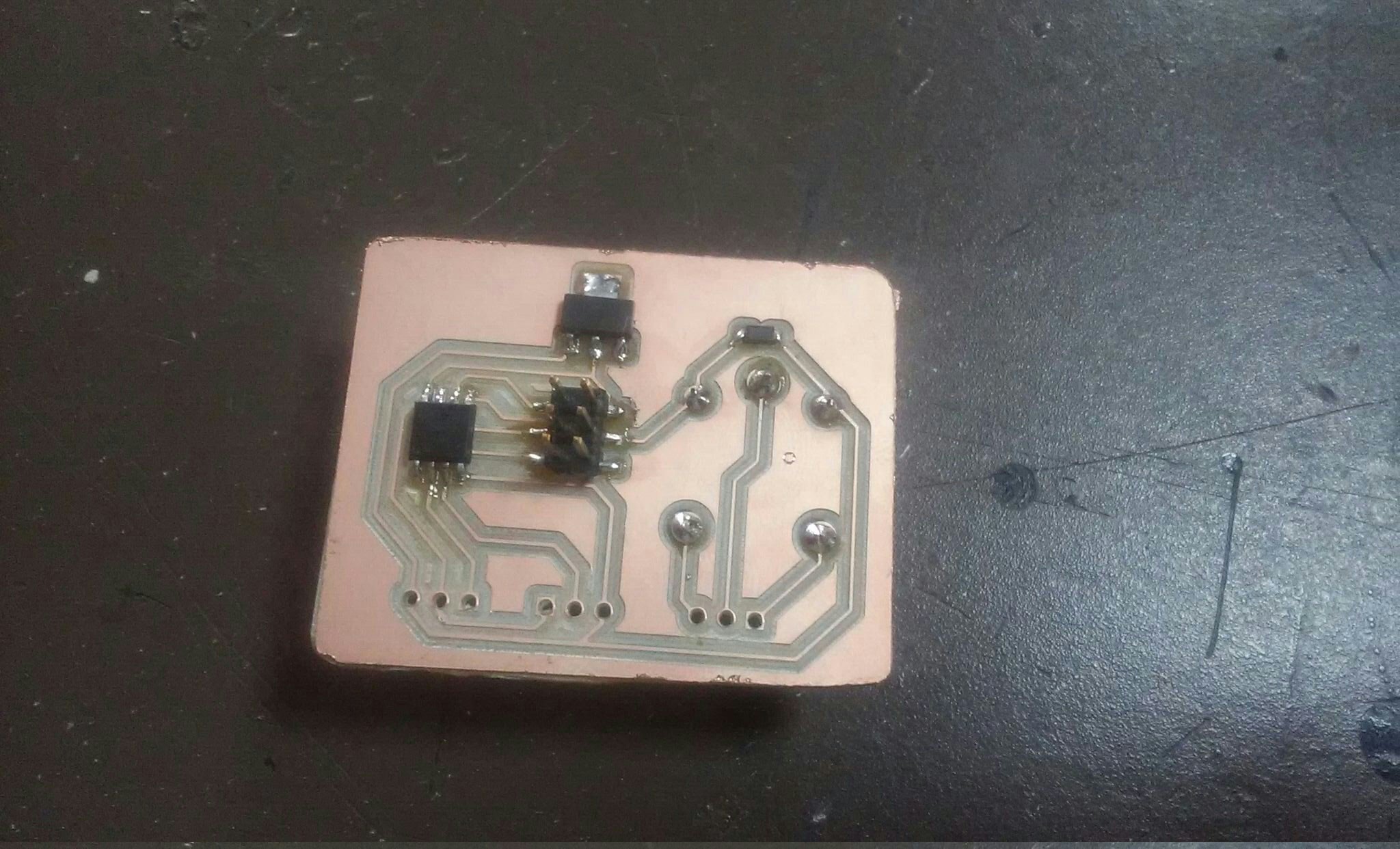
This is how milling the traces of the PCB looks like on it.
From there I drilled the holes and cutted the outline to remove it.
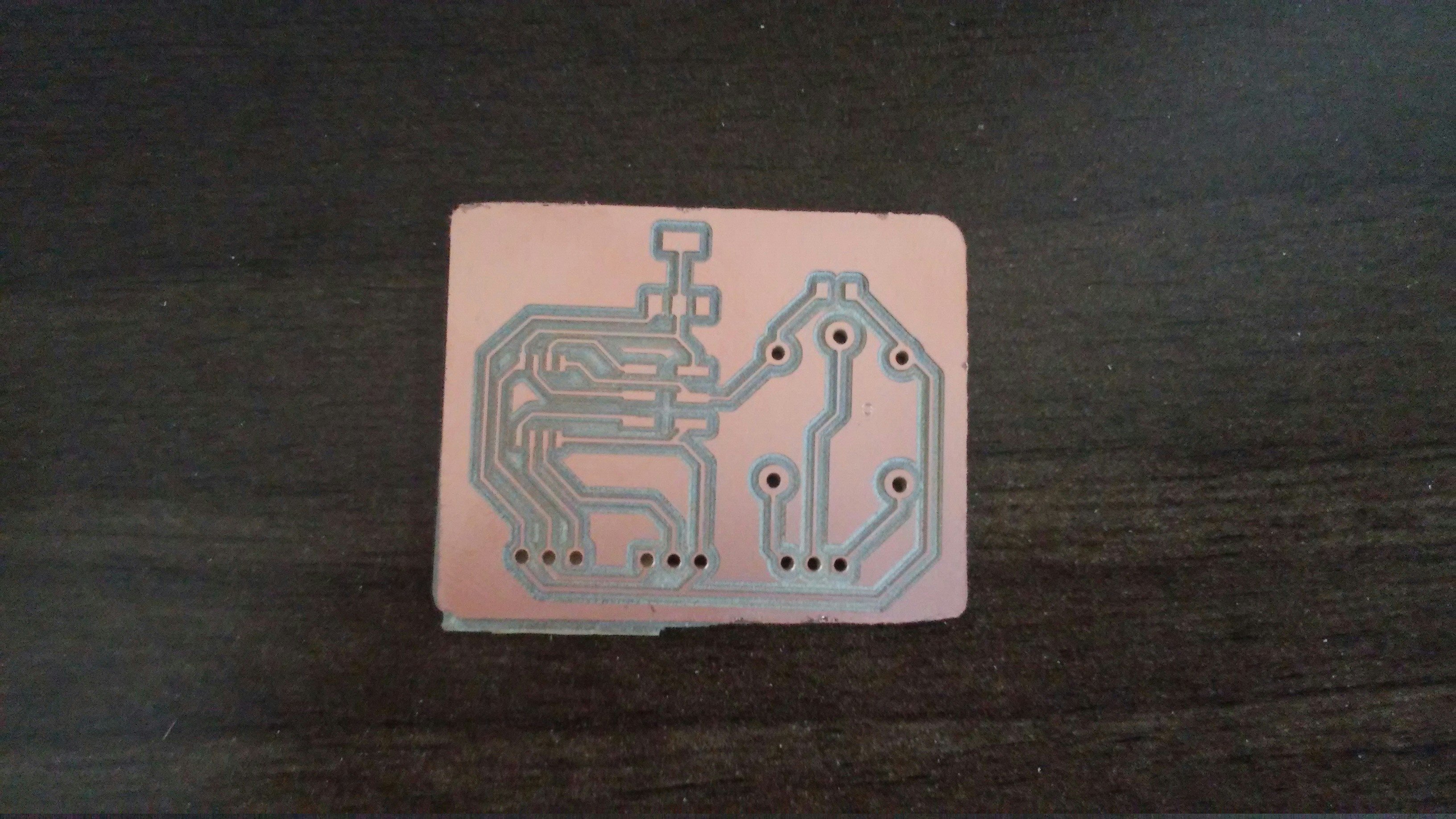
As you can see on the side there was some trouble cutting the outline and this was due to the board that wasn't firmly attached to the base and it started moving while I was cutting the outline.
I solder the components to the board.
The following is to program the board.
Program
Below is the program I used in the board to control the system.
const int pinRelay = PB0;
const int pinPIR = PB4;
const int pinRGB = PB3;

const int calibrationTime = 30;
volatile int candidatePIR;
int statusPIR = HIGH;
volatile boolean changePIR = false;
volatile long unsigned int changeTimePIR = 0;
const long unsigned int delayNoise = 1000;

void interruptPIR () {
	int readPIR = digitalRead(pinPIR);
	if (statusPIR != readPIR) {
	changePIR = true;
	candidatePIR = readPIR;
	changeTimePIR = millis();
	}
	else {
	changePIR = false;
	}
}

bool isMovementPIR() {
	if (changePIR == true) {
	if ((millis() - changeTimePIR) > delayNoise) {
		statusPIR = candidatePIR;
		changePIR = false;
	}
	}
	return (statusPIR == LOW);
}

void setup() {
	pinMode(pinRelay, OUTPUT);
	pinMode(pinPIR, INPUT);
	pinMode(pinRGB, OUTPUT);
	digitalWrite(pinPIR, HIGH);

	for(int i=0; i<calibrationTime; i++){
	delay(1000);
	}

	attachInterrupt(0, interruptPIR, CHANGE);
}

void loop() {
	if (isMovementPIR()) {
	digitalWrite(pinRelay, HIGH);
	}
	else {
	digitalWrite(pinRelay, LOW);
	}
}
Electronic Cover
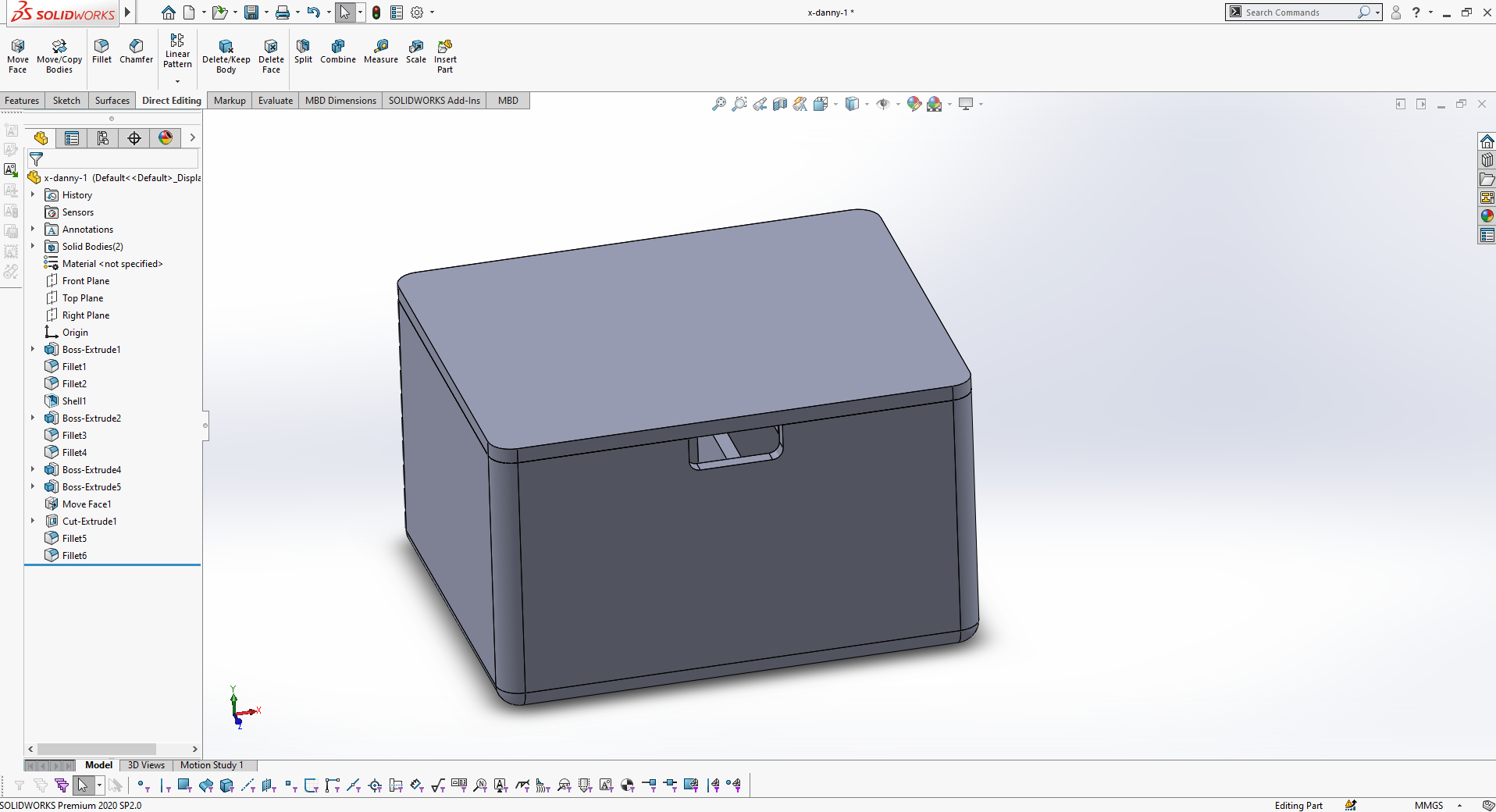
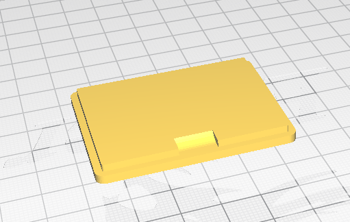
I designed also a cover for the electronic circuit and printed it.
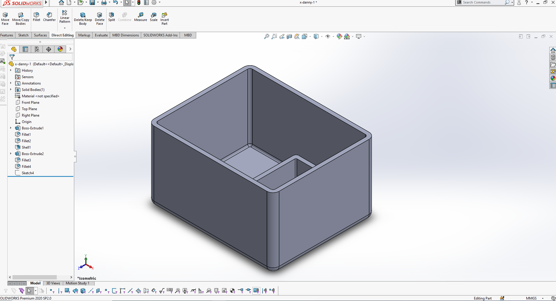
This is the assembly of the cover.
I printed the cover and here I was setting the parameters.
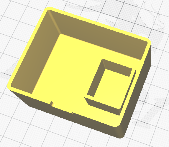
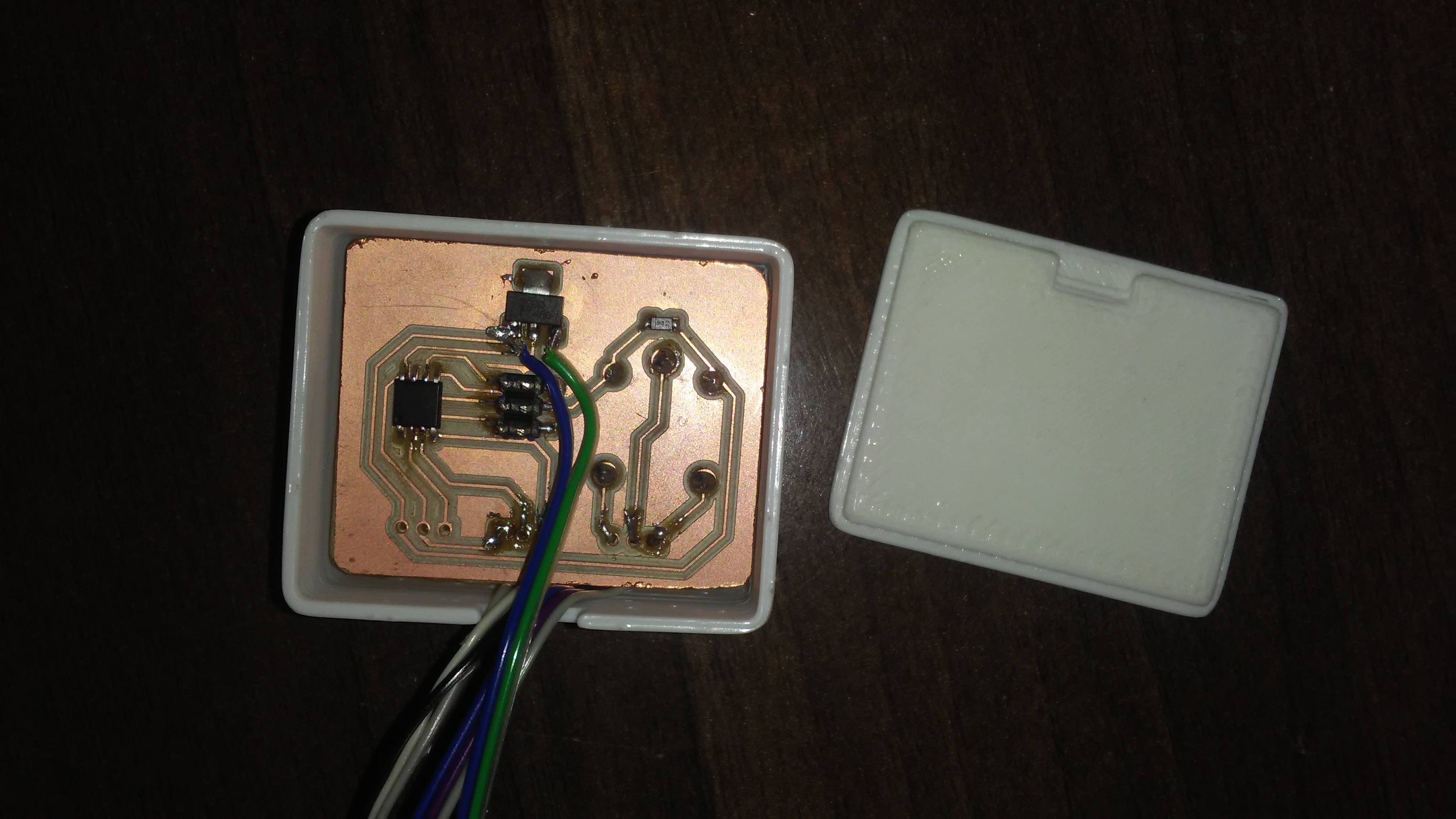
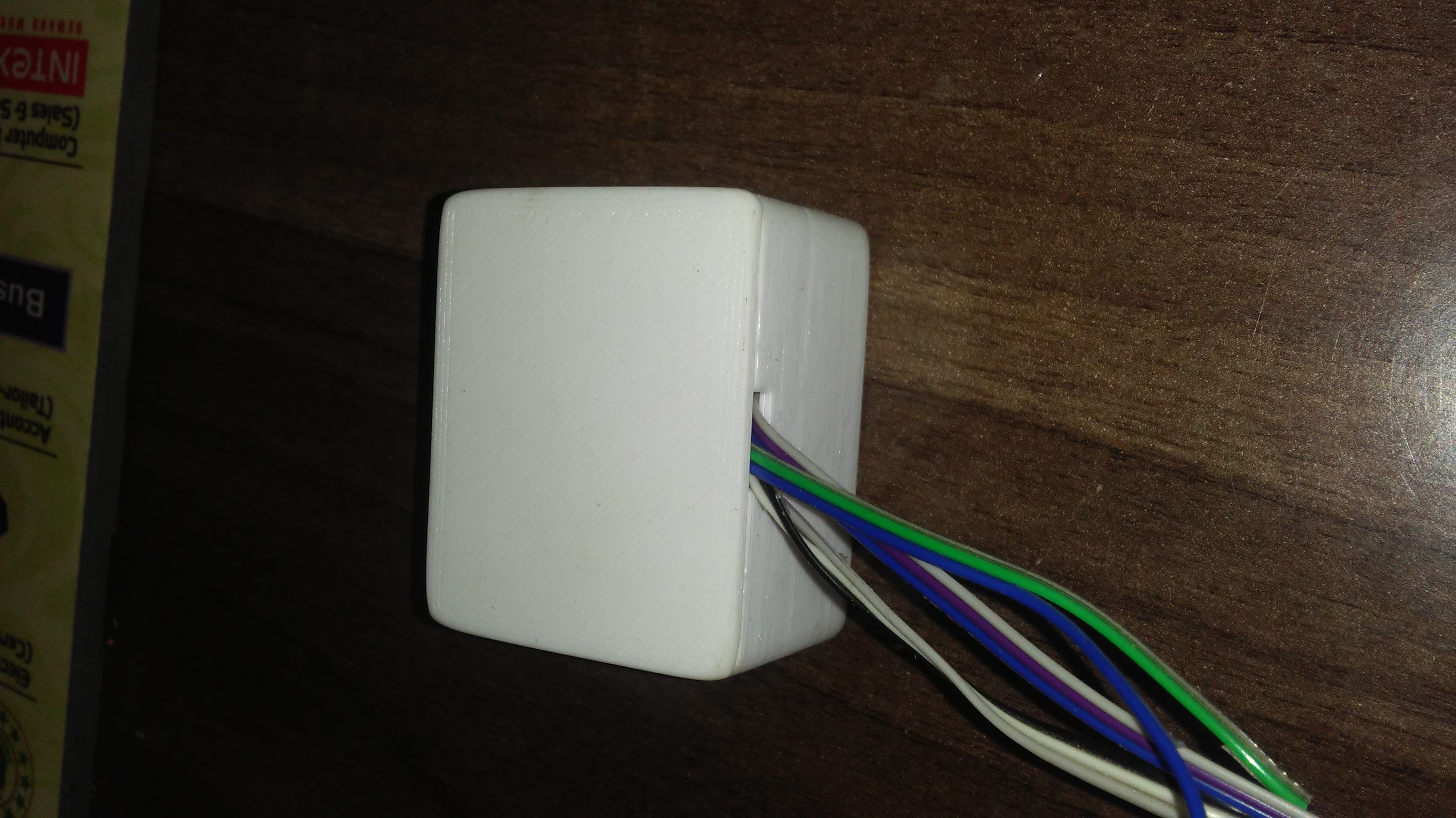
Here is the final print with the electronics in it.
Presentation video
Files used can be found here.