Week 10: Input devices
Assignment
For this assignment we are asked to add a sensor to the microcontroller and read its output.
I used a PIR sensor, it senses the motion of a warm body and activates a pin to high for a certain amount of seconds.
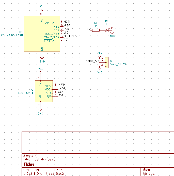
First I designed the circuit, in place of the sensor I replaced it with a connector because that's how the sensor is made to be connected.
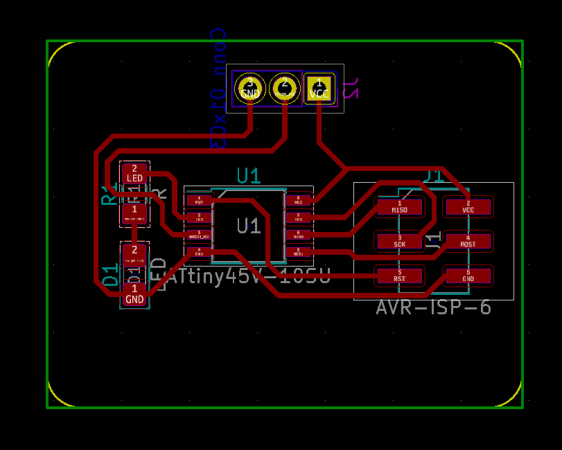
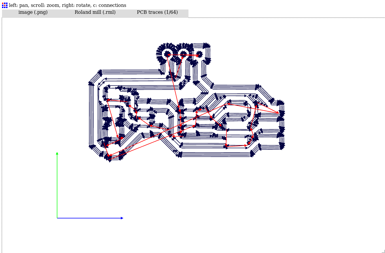
I moved on to create PCB traces of the circuit.
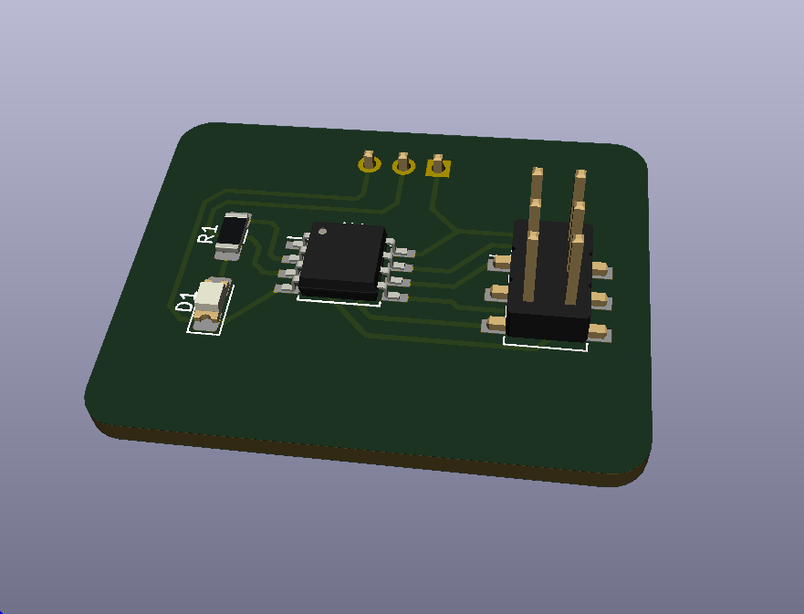
Now that I was done with PCB lets take a look on the 3D view of the final circuit.
Since everything looks good it was time to move to generate RML file for milling the board.
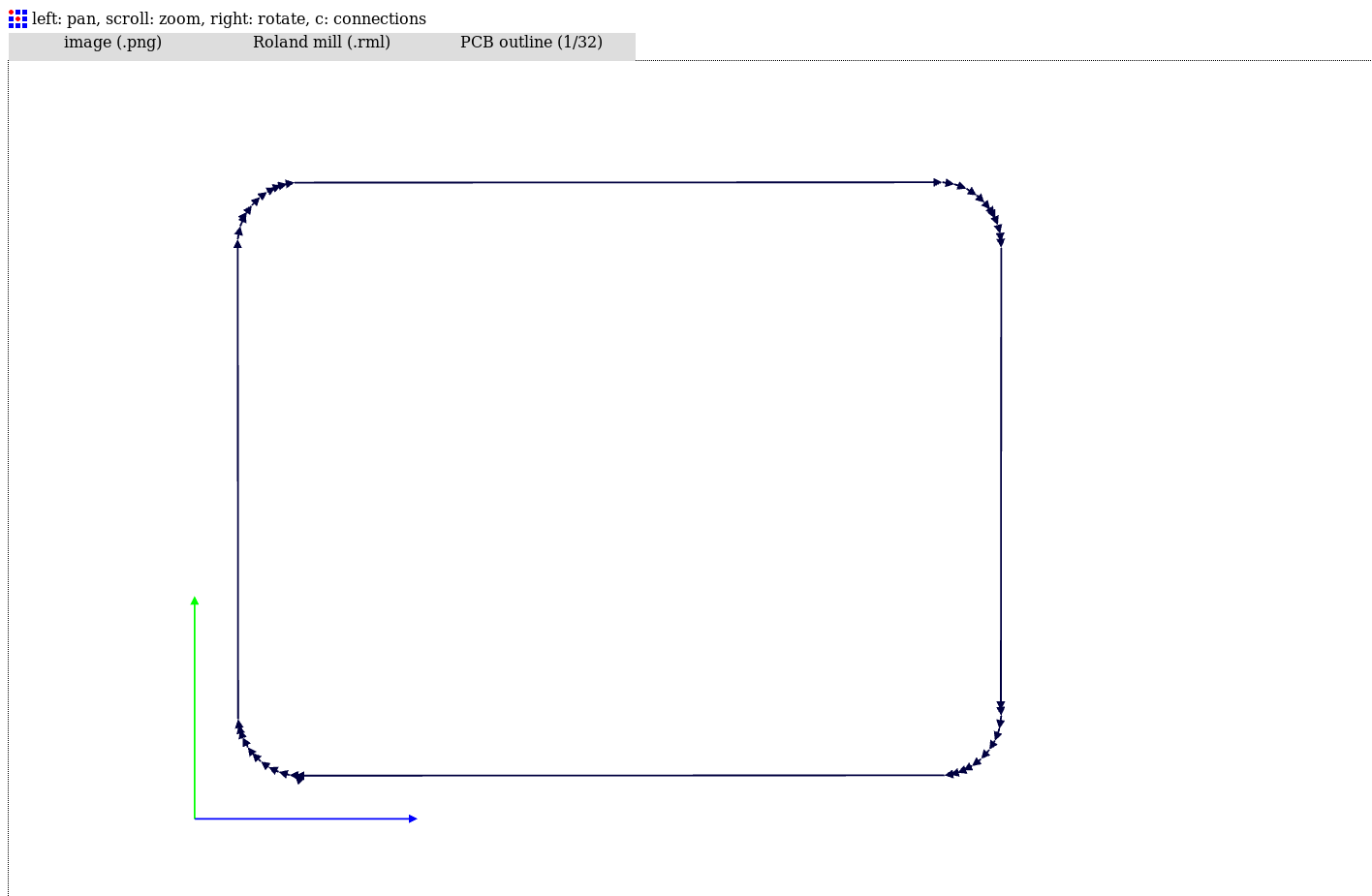
And this is the path for traces.
From here I proceded to milli the board.
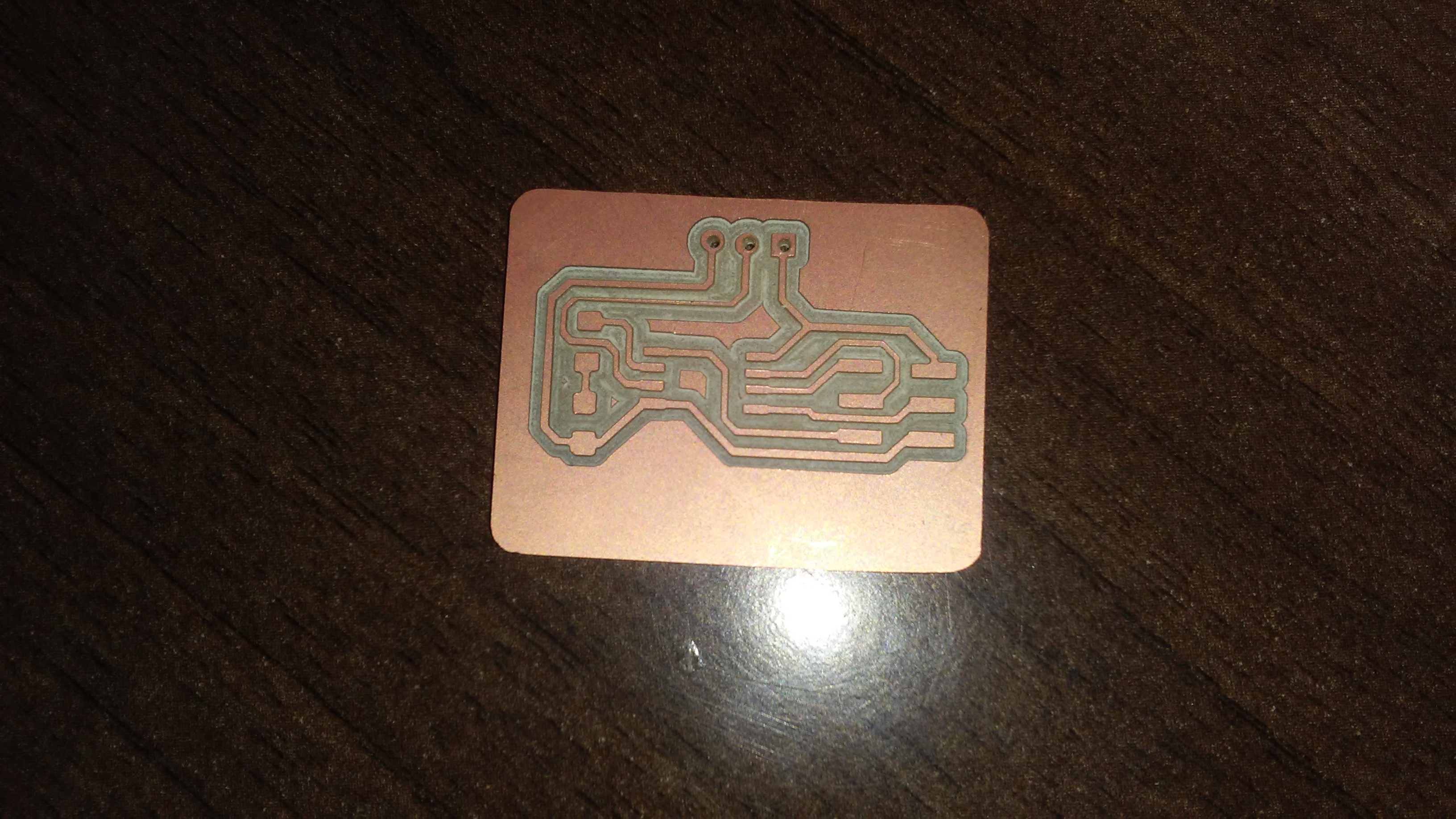
This is the milled board.
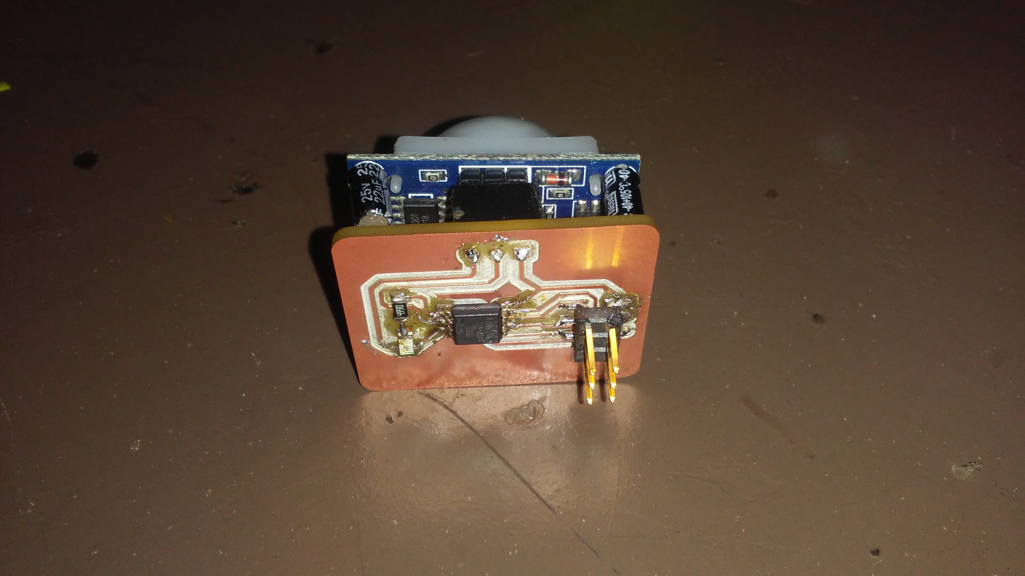
Now I soldered all components on the board and this is its look.
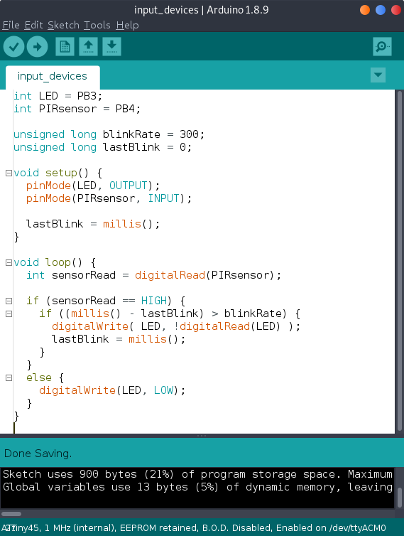
The next step is to program the board and here is the program I wrote for it.
int LED = PB3;
int PIRsensor = PB4;

unsigned long blinkRate = 300;
unsigned long lastBlink = 0;

void setup() {
    pinMode(LED, OUTPUT);
    pinMode(PIRsensor, INPUT);

    lastBlink = millis();
}

void loop() {
    int sensorRead = digitalRead(PIRsensor);

    if (sensorRead == HIGH) {
        if ((millis() -lastBlink) > blinkRate) {
            digitalWrite( LED, !digitalRead(LED) );
            lastBlink = millis();
        }
    }
    else {
        digitalWrite(LED, LOW);
    }
}
And the image of the program in Arduino IDE.
below it is the video of the project working
Files used in design of the circuit and the program can be found here.