Week 16. Interface and application programming.

Go to:
1. Group work
Task: Compare as many tool options as possible.
Group:
This week we did the group work together with whole Oulu group. Several of us used Processing, one used Blynk, one PyQt5. Here is some comparison of the used programs.
Processing
Processing is a flexible software sketchbook and a language for learning how to code within the context of the visual arts. Since 2001, Processing has promoted software literacy within the visual arts and visual literacy within technology. There are tens of thousands of students, artists, designers, researchers, and hobbyists who use Processing for learning and prototyping.
- Free to download and open source
- Interactive programs with 2D, 3D, PDF, or SVG output
- OpenGL integration for accelerated 2D and 3D
- For GNU/Linux, Mac OS X, Windows, Android, and ARM
- Over 100 libraries extend the core software
Blynk
Blynk supports hardware platforms such as Arduino, Raspberry Pi, and similar microcontroller boards to build hardware for your projects.
Blynk supports the following connection types to connect your microcontroller board (hardware) with the Blynk Cloud and Blynk’s personal server:
- Ethernet
- Wi-Fi
- Bluetooth
- Cellular
- Serial
PyQt5
Qt is set of cross-platform C++ libraries that implement high-level APIs for accessing many aspects of modern desktop and mobile systems. These include location and positioning services, multimedia, NFC and Bluetooth connectivity, a Chromium based web browser, as well as traditional UI development.
PyQt5 is a comprehensive set of Python bindings for Qt v5. It is implemented as more than 35 extension modules and enables Python to be used as an alternative application development language to C++ on all supported platforms including iOS and Android.
PyQt5 may also be embedded in C++ based applications to allow users of those applications to configure or enhance the functionality of those applications.
2. Individual assignment
Task: Write an application that interfaces a user with an input &/or output device that you made.
This week was full of amazing discoveries. At the start, I was going to use my pcb from Input Devices week. It is my second version of the Hello Word board. It has two 4-pin headers to make it easy to work with other boards I make. For this week, I used the Light sensor board connected to one of 4-pin headers on the board (photosensor on pin A3). I faced serious troubles with writing my own code to transmit data to the serial port from atTiny44, so I used my Light sensor board and Arduino uno at first. Then, with some help from Iván Sánchez Milara I made it work.
Go to ATtiny and serial part
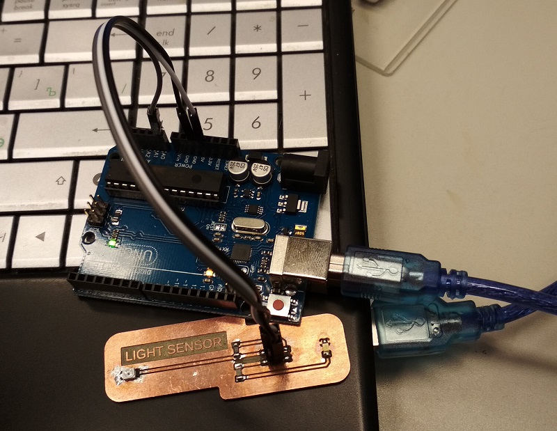
The sensor is connected to A0 pin on the Arduino, Vcc to 5V and GND to GND, pin with LED is not used. Arduino is connected to the USB port.
After a very nice lecture by Ivan Sanchez Milara I've decided to try Processing to write a simple programm to display the data from the sensor. For a long time I was going to start programming on Python, but it is not one week task. Ivan's lecture just pushed me to start sooner. Anyway, Arduino IDE and Processing match well together.
I found a very nice and simple tutorial on the internet. My Arduino sketch is based on it, but I made some improvements. Value from the sensor can be from 0 to 1023. To squeeze that value into one bit of data author of the tutorial divides the sensor value by 4. Instead of that, I use map function. It gives a similar result but better suits serial communication tasks.
//Reads data from a sensor and sends it to the serial port

#include <SoftwareSerial.h>
const int pResistor = A0; // sensor pin
uint16_t value; // Store value from photoresistor (0-1023)

void setup() {
  while (!Serial) {
    ; // wait for serial port to connect. Needed for native USB port only
  }
  // set the data rate for the SoftwareSerial port
  Serial.begin(9600);
 // Serial.println("Hello, world");//test message
}

void loop() {
   int value = analogRead(pResistor);   //
   map(value, 0, 1023, 0, 255);       //mapping to fit in one bit of data.
   Serial.write(value);                 // sends the value in bin
   //delay(100); // delay
}
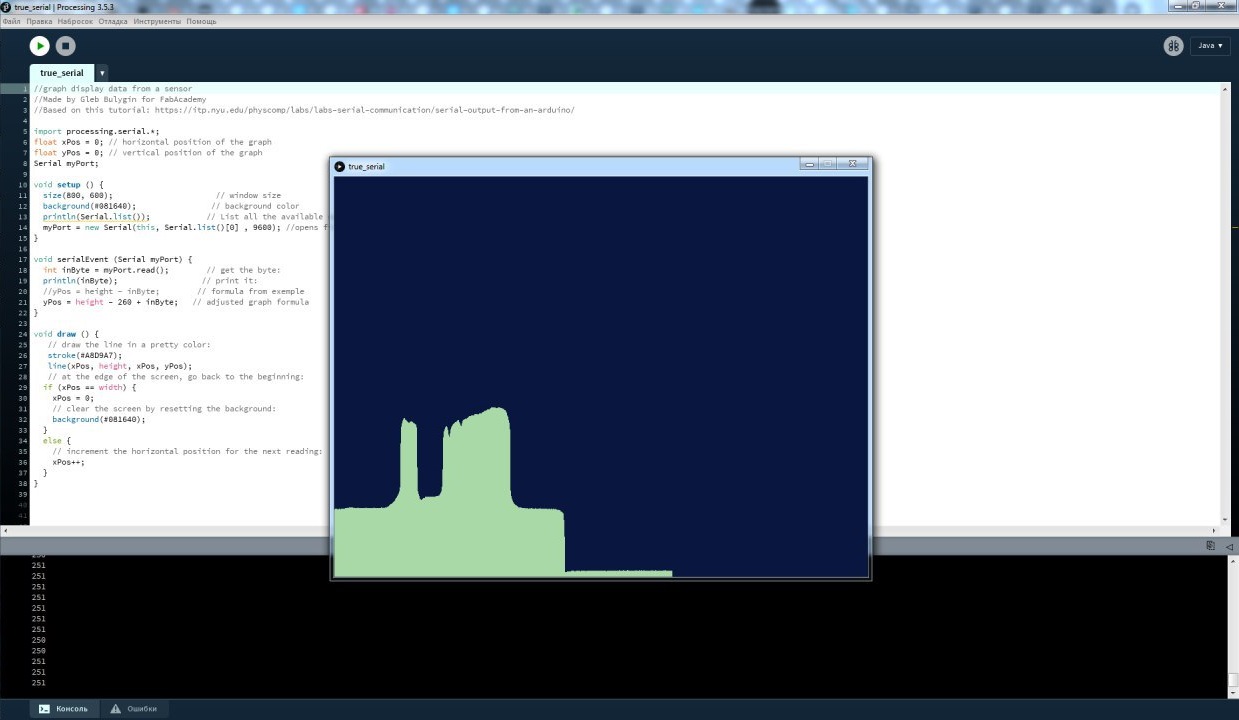
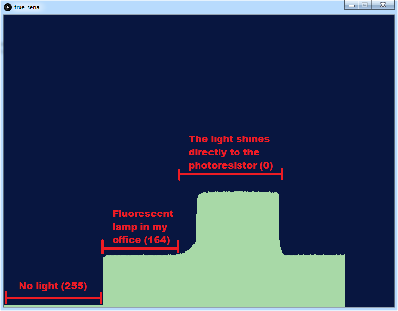
Then I made a new sketch in Processing. My code is based on the same tutorial. The code is simple. It reads a value from the serial port and draws a vertical line in the program window. When lines reach the edge of the window, the program resets the background and zeros X-position.
I faced a few minor problems with the code, but nothing seriuos.
• Divide the sensor value by 4 didn't really worked for me. So I was checking the port speed, connections, air temperature... Then I've found mapping function for Arduino IDE, edited my Arduino sketch and everything worked. In Putty terminal binary data was shown like a random symbols, but in CoolTerm in HEX mode everything was displayed correctly. And it worked with my Processing program.
• The port opening code from the exemple didn't work for me, so I've found how to make it work: I'm checking all the ports (most likely there will be only one port) and open the first one.
//graph display data from a sensor

import processing.serial.*;
float xPos = 0; // horizontal position of the graph
float yPos = 0; // vertical position of the graph
Serial myPort;

void setup () {
  size(800, 600);                      // window size
  background(#081640);                // background color
  println(Serial.list());            // List all the available serial ports
  myPort = new Serial(this, Serial.list()[0] , 9600); //opens first found port on 9600bps
}

void serialEvent (Serial myPort) {
  int inByte = myPort.read();        // get the byte:
  println(inByte);                  // print it:
  //yPos = height - inByte;        // formula from exemple
  yPos = height - 260 + inByte;   // adjusted graph formula
}

void draw () {
   // draw the line in a pretty color:
   stroke(#A8D9A7);
   line(xPos, height, xPos, yPos);
   // at the edge of the screen, go back to the beginning:
  if (xPos == width) {
    xPos = 0;
    // clear the screen by resetting the background:
    background(#081640);
  }
  else {
    // increment the horizontal position for the next reading:
    xPos++;
  }
}
ATtiny and serial
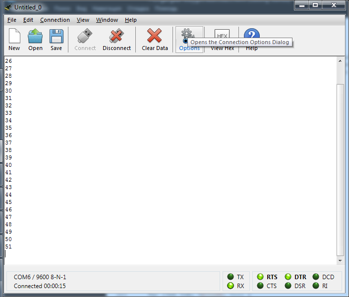
I can't tell you what exactly I did wrong. I burned the bootloader on my Hello Word board with right configuration (external clock 20MHz) and uploaded a simple Arduino sketch. It sends numbers from 1 to 100 to the serial port on 9600 pbs. The whole process of programming ATtinys with Arduino IDE is described on Embedded programming page. ATtiny is connected to my PC via FTDI cable.
#include <SoftwareSerial.h>

// ***
// *** Define the RX and TX pins. Choose any two
// *** pins that are unused. Try to avoid D0 (pin 5)
// *** and D2 (pin 7) if you plan to use I2C.
// ***
#define RX    A0   // *** D3, Pin 2
#define TX    A1   // *** D4, Pin 3

// ***
// *** Define the software based serial port. Using the
// *** name Serial so that code can be used on other
// *** platforms that support hardware based serial. On
// *** chips that support the hardware serial, just
// *** comment this line.
// ***
SoftwareSerial mySerial(RX, TX);

void setup() {
  mySerial.begin(9600);
}
/*
void loop() {
Serial.print(177);
delay(500);
}*/

void loop() {
  for (int i=0; i<100; i++) {
    mySerial.println(i);
    delay(500);
  }
}
And I can see it in the terminal (com6: 9600/8/N/1). I used Putty terminal before. Now I'm using CoolTerm.
Then I edited code I used with Arduino UNO to make it work with ATtiny:
//Reads data from a sensor and sends it to the serial port

#include <SoftwareSerial.h>
const int pResistor = A3; //sensor pin
uint16_t value; // Store value from photoresistor (0-1023)
#define RX    A0   // *** D3, Pin 2
#define TX    A1   // *** D4, Pin 3
SoftwareSerial mySerial(RX, TX);

void setup() {
  while (!mySerial) {
    ; // wait for serial port to connect. Needed for native USB port only
  }
  // set the data rate for the SoftwareSerial port
  mySerial.begin(9600);
  pinMode(pResistor, INPUT);// Set pResistor - A3 pin as an input (optional)
}

void loop() {
  int value = analogRead(pResistor);   //
  map(value, 0, 1023, 0, 255);       //mapping to fit in one bit of data.
  mySerial.write(value);                 // sends the value to serial port in bin
}
On the video you can see how it works. The background and horisontal position are reset at the beginning. Then I close the photoresistor (the board sends something like 220-230 to the port) and the line height on the screen drops down.
3. App for the final project
The most part of this week I dedicated to planning and building an Android App to control addressable LED stripe from a smartphone via Bluetooth. Unfortunately, I haven't move so far in that direction. But I've read and watched a lot of tutorials. The pcb for my final project is in development sate, but it is close to the final look.
This is an example how I want it to look like.
4. The Results of the week
- I briefly learned how to write on Processing
- All mechanical parts for my final project are ready to print.
- I finally got the Bluetooth module (BL652-SA-01)
- The app for the final project is in development state
- I'm planning to finish the pcb for the final project in a week or so.