Week 03:Computer-controlled Cutting
Computer-controlled cutting is a subtractive manufacture method, in which the computer controls an effector (a knife, laser, water jet, hot wire, endmill), based on a digital design file. Machines that we covered this week include laser cutter and vinyl cutter.
Laser Cutting: Study of Panopticon
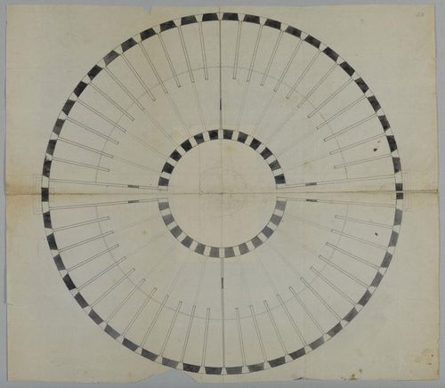
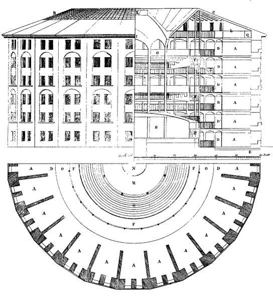
I was interested in the structure of a panopticon. It is a hypothetical prison proposed by English philosopher Jeremy Bentham in the late 18th century. The structure of the building suggests an institution to be observed by a single watchman without the inmates being able to tell whether or not they are being watched. As you can see in the diagram below, it is a circular structure where the watch tower is in the middle of the building. Where the watchman is, however, remains uncertain. Meanwhile, the panopticon remains a closed structure. Part of the assignment this week is to make a parametric press-fit construction kit. It would be interest to create a modular and study the hierarchal relationship between the watchman and the prisoner in the panopticon structure.
Design in Fusion
First, I made my design in FUSION 360.

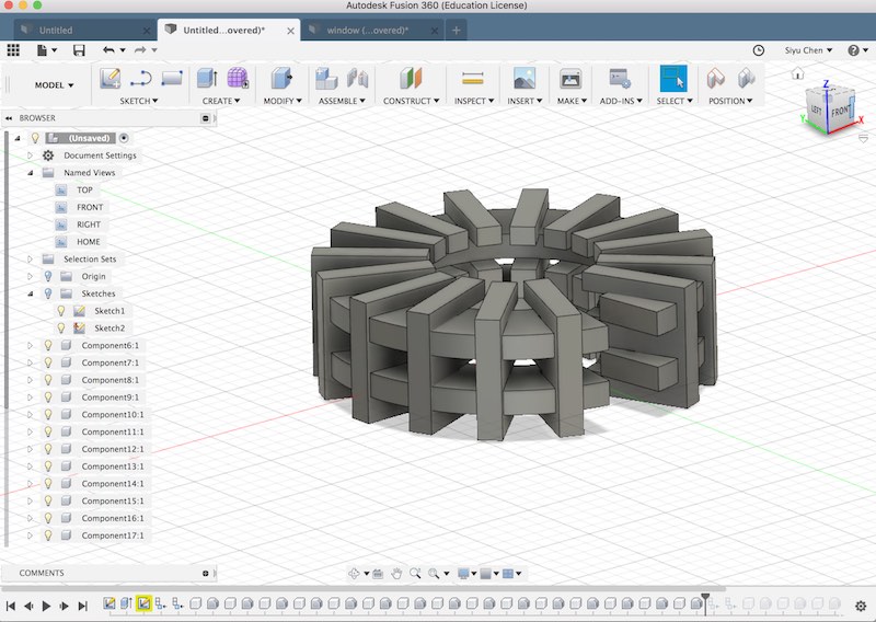
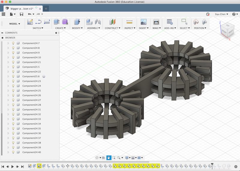
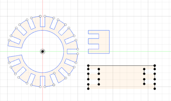
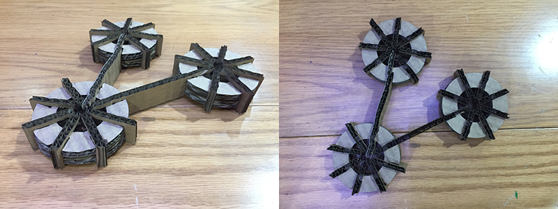
I designed a single Panopticon structure first. Then, by extending the connecting structures, I could make multiple panopticons connect together, resulting in an infinite modular structure.
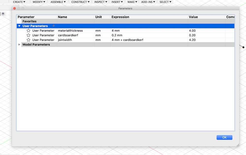
I decided to use 4mm thick cardboard for the structure. Although the material thickness is 4mm, some material will be burnt away by the laser during cutting. It is important to do a material KERF test before finalizing the dimensions on the design, which allows you to understand the amount of material that gets burnt by the laser. Based on my classmate's tests, the kerf for 4mm cardboard is around 0.2mm, while for plywood is 0.1mm. Later in my final project, I have learned kerf for 3mm acrylic is around 0.18mm.
I added 0.2mm kerf to the connecting parts of the joints. Instead making the joint 4mm of the material thickness, it is 4.2mm. On Fusion, I inserted the measurements into user parameter. If the dimension changes, I can make the change in user parameter, which automatically applies to all measurements in the model.
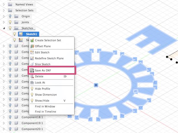
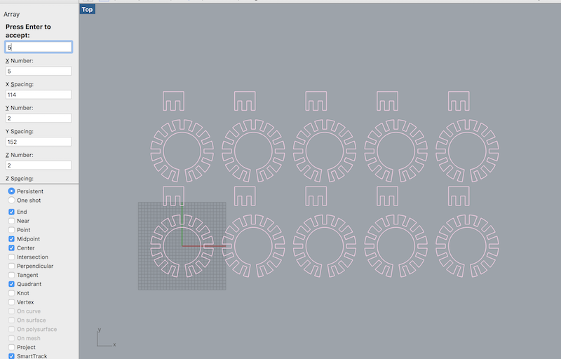
Then I exported my design as .dxf into Rhino in order to make multiples of the modulars I have created from the model.
The RECTANGULAR ARRAY tool  allows you to create multiples of a singular modular:
Set up for cutting
In illustrator:
1. All the path for cutting has to be made into 0.05 mm and all colors have to be in RGB.
2. Assign laser setting to each color: power, speed, ppi (how rapid the laser fires) make sure check/test the setting for the material you are using beforehand.
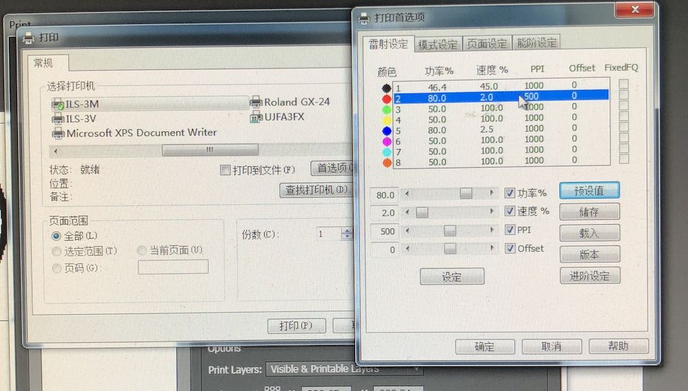
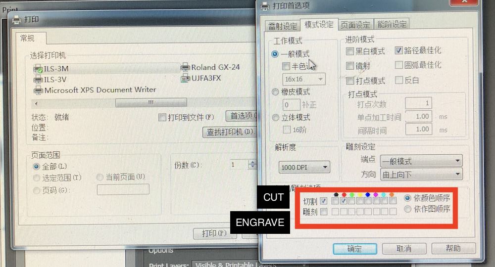
3. Determine engrave/cut path: engrave always happen before cutting. In this case, there is only one cutting layer.
4. Set cutting sequence: sequence for cutting is by color (you can find the color sequence in the images below), meaning the path in black cuts before red.
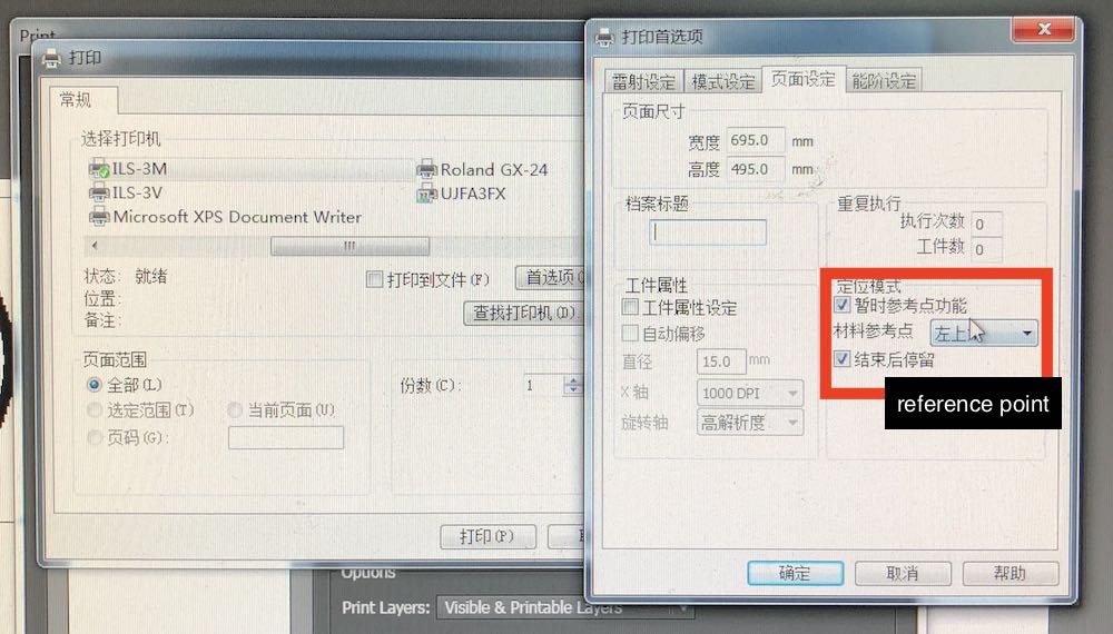
5. Set the drawing ref point: where the laser refers too as the starting point. I usually use top left.
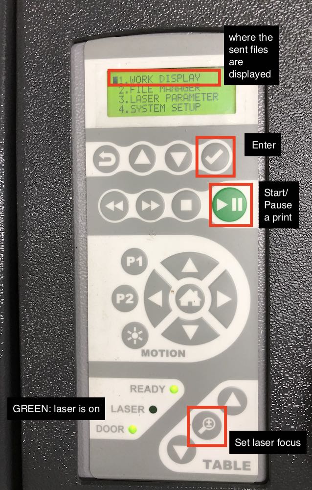
On laser cutter:
1. Turn on the laser cutter, the airflow and the exhaust filter
2. Lay the material flat on the bed and focus the laser head *make sure to do it every time the type and the thickness of the material defers
3. Send the file from the computer *if the machine beep once, pause and beep twice, this means your file has been sent successfully
4. Turn on the laser
5. Select the file on the laser cutting control panel and start cutting
I was away from Shanghai in the week. Documentation on the group assignment can be found from my classmate's page. Later during the course of fab academy, I have used laser cutter extensively, especially in my final project. I made parametric designs in both wood and acrylic. Here are some of the settings I have been using throughout the course:
4mm cardboard: 65% power, 10% speed, 500 ppi
3mm acrylic: 75% power; 1.5% speed, 1000 ppi
5mm acrylic: 85% power; 0.5% speed, 1000 ppi
5mm plywood: 80% power; 2% speed, 500 ppi
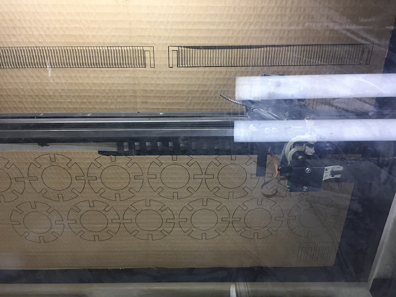
Result
Here is the result of the cut:
I also made a living hinge to make the structure looks like an eye in bird-eye view. It could have been better designed to merge the living hinge together with the other structures.
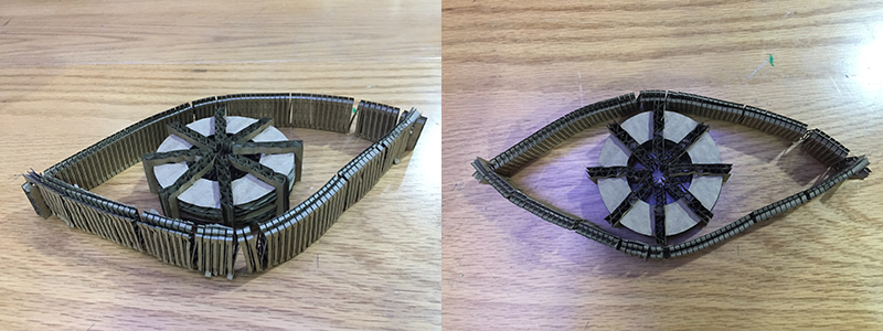
The joint was difficult to fit together. Luckily I used cardboard, which allows some flexibility in the dimension. If I made my design in wood, I would not be able to fit the joint together without a hammer. In the future, I would need to do some joint tests after kerf test in understanding the tension of the joint with different dimensions.
Vinyl Cutting: Stickers
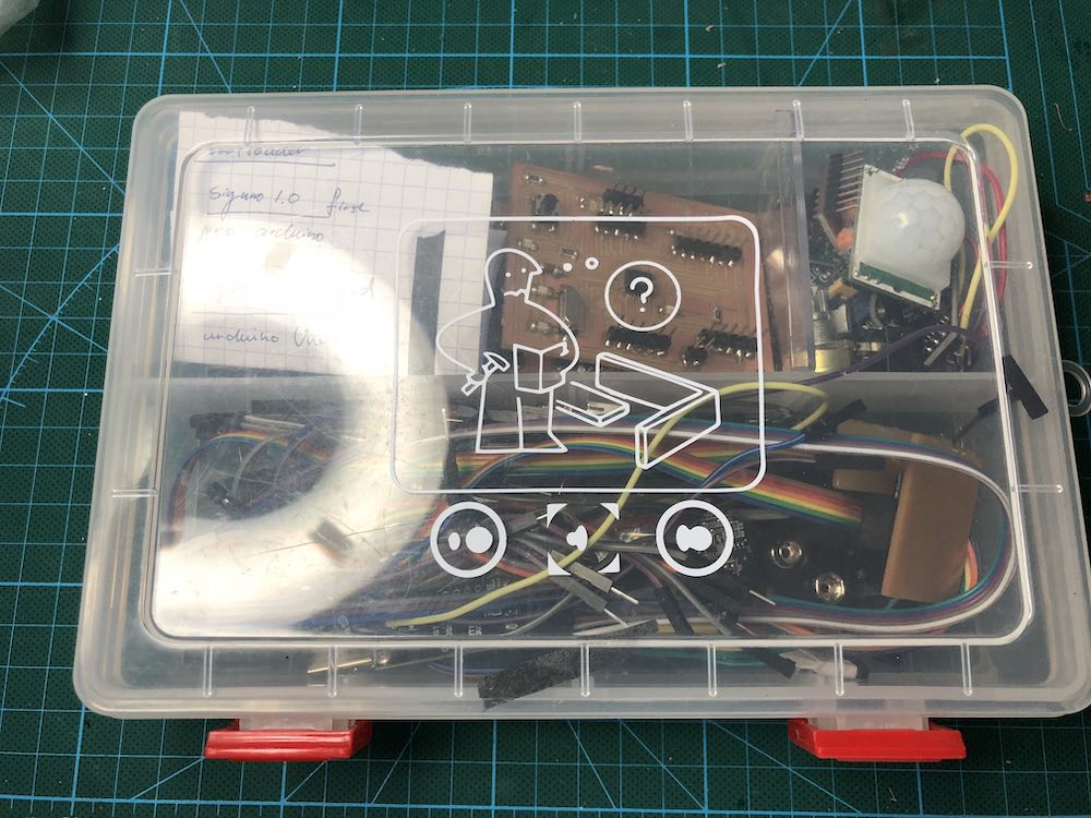
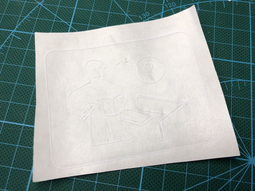
For the vinyl cutting assignment, I made stickers based on my final project logo. I also made a sticker directly from the graphic of a IKEA manual. The graphic speaks to my electronics debugging process at fab academy :O
First, I prepared the vector files in illustrator.
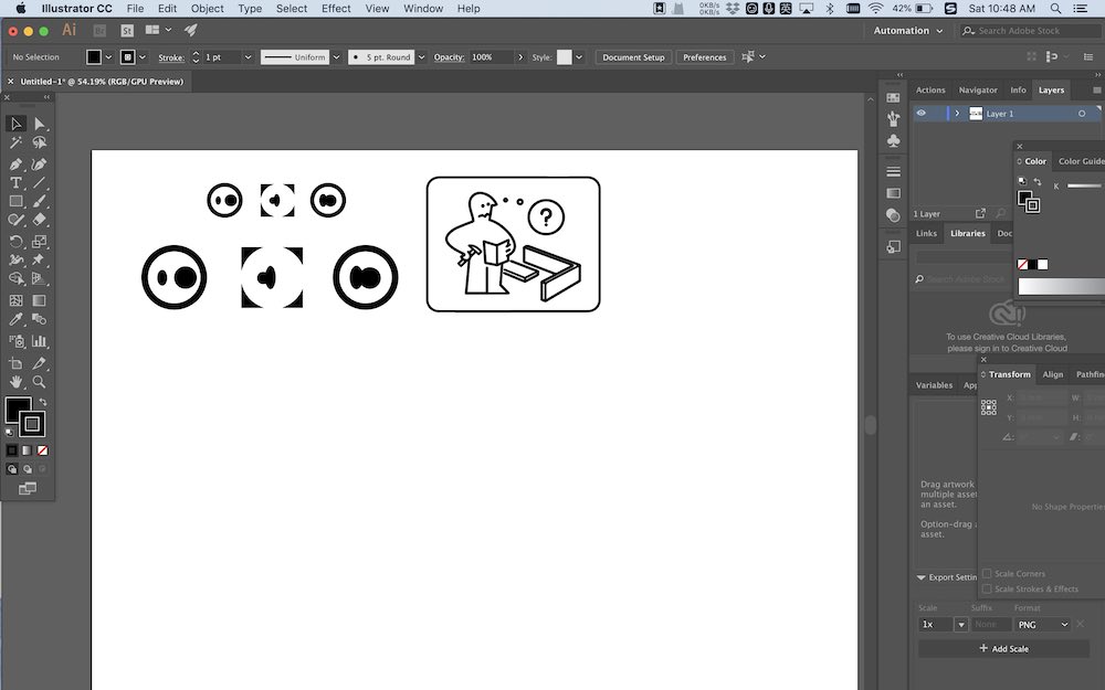
I exported the file in .EPS version 3 of illustrator format, which can be read by cut studio.
Set up for cutting
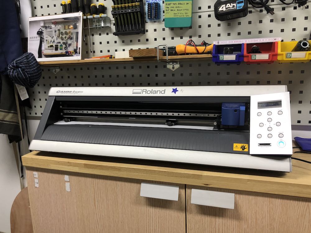
The vinyl cutter we use at the fab lab is a Roland GX-24. To set up the printer, here is the procedure:
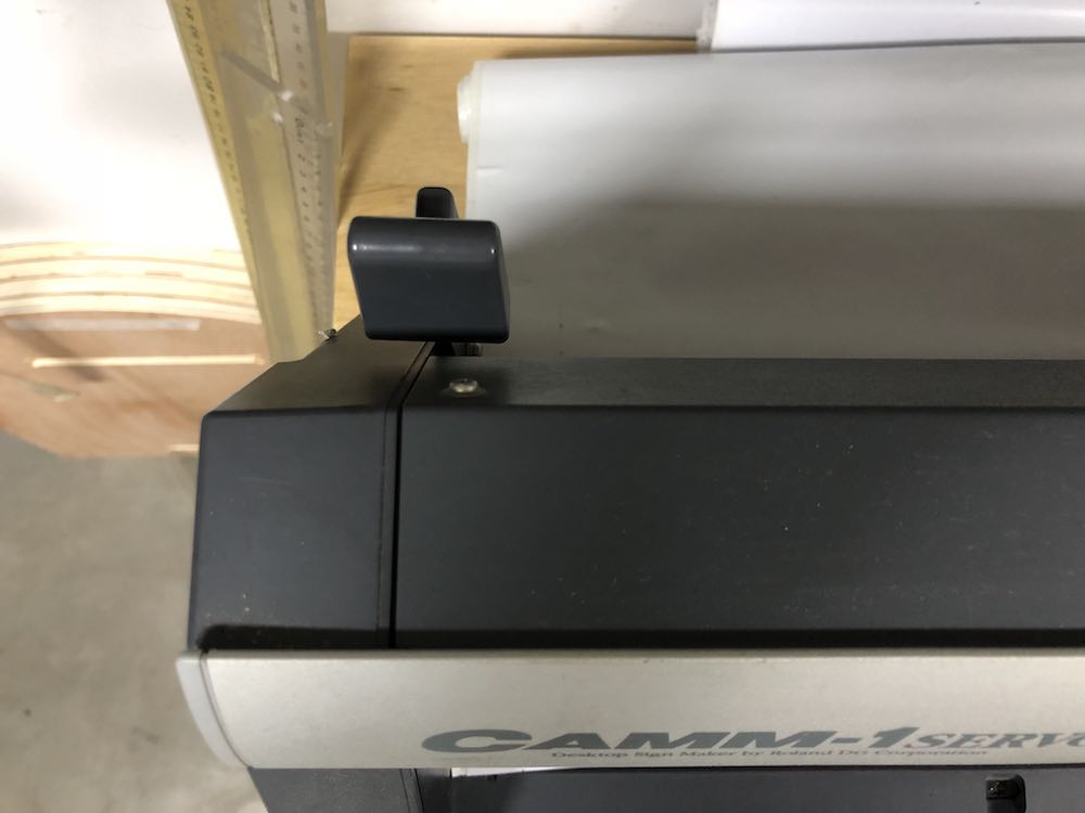
1. Insert the cutting material. Make sure it is held under the two pinch rollers and clipped down after inserting.
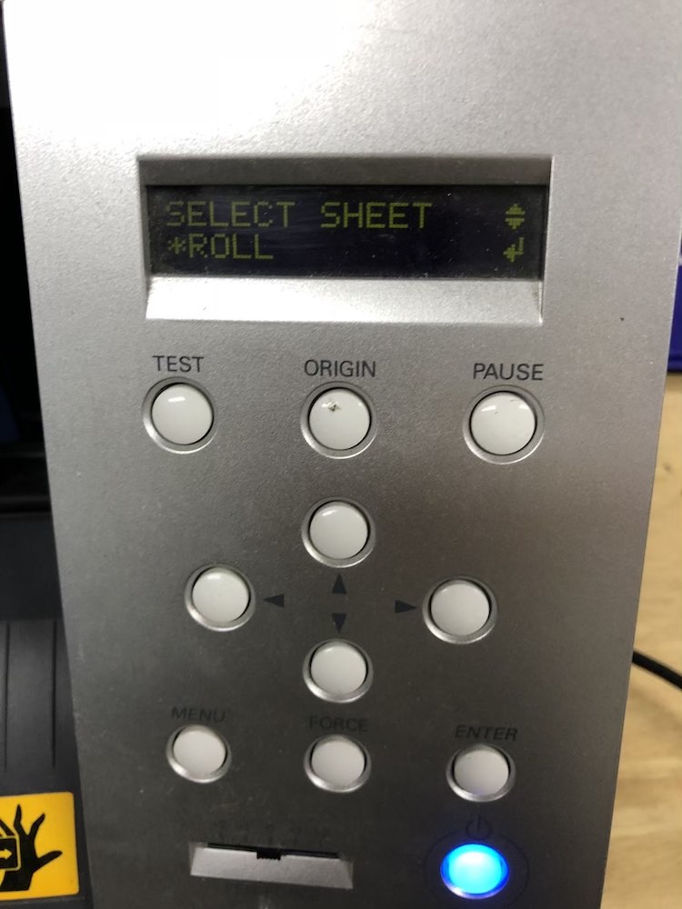
2. Then, select the material as ROLL on the control panel.
3. Make sure the cutting blade is out.
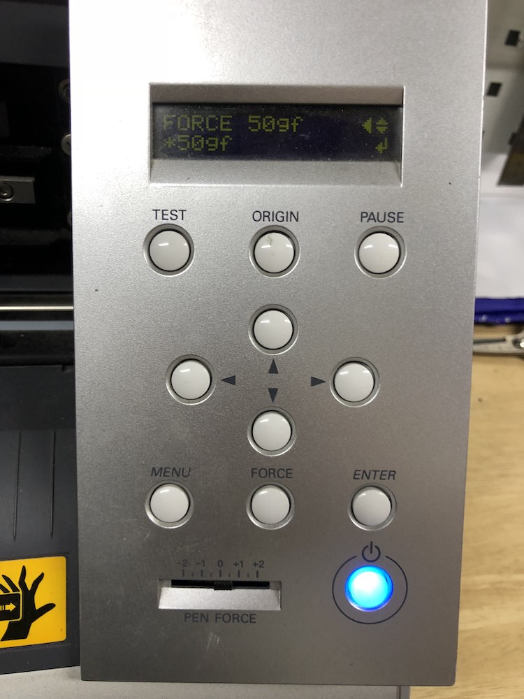
4. Select the FORCE value for the blade. Do a TEST by holding the test button for a few second.
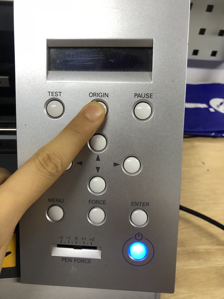
5. Position the blade at desired origin point and hold the ORIGIN button for a few second.
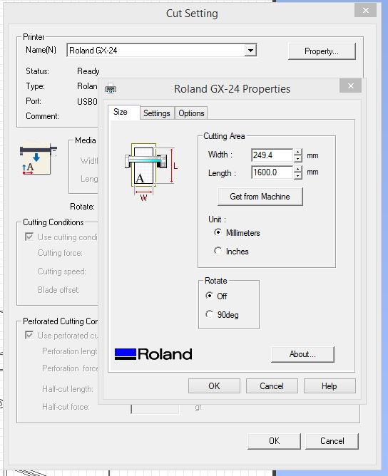
6. On cut studio: File/Cut Setting, make sure the right printer is selected. Under Properties, click on Cutting Area/Get from Machine in order for the software to recognize the cutting area.
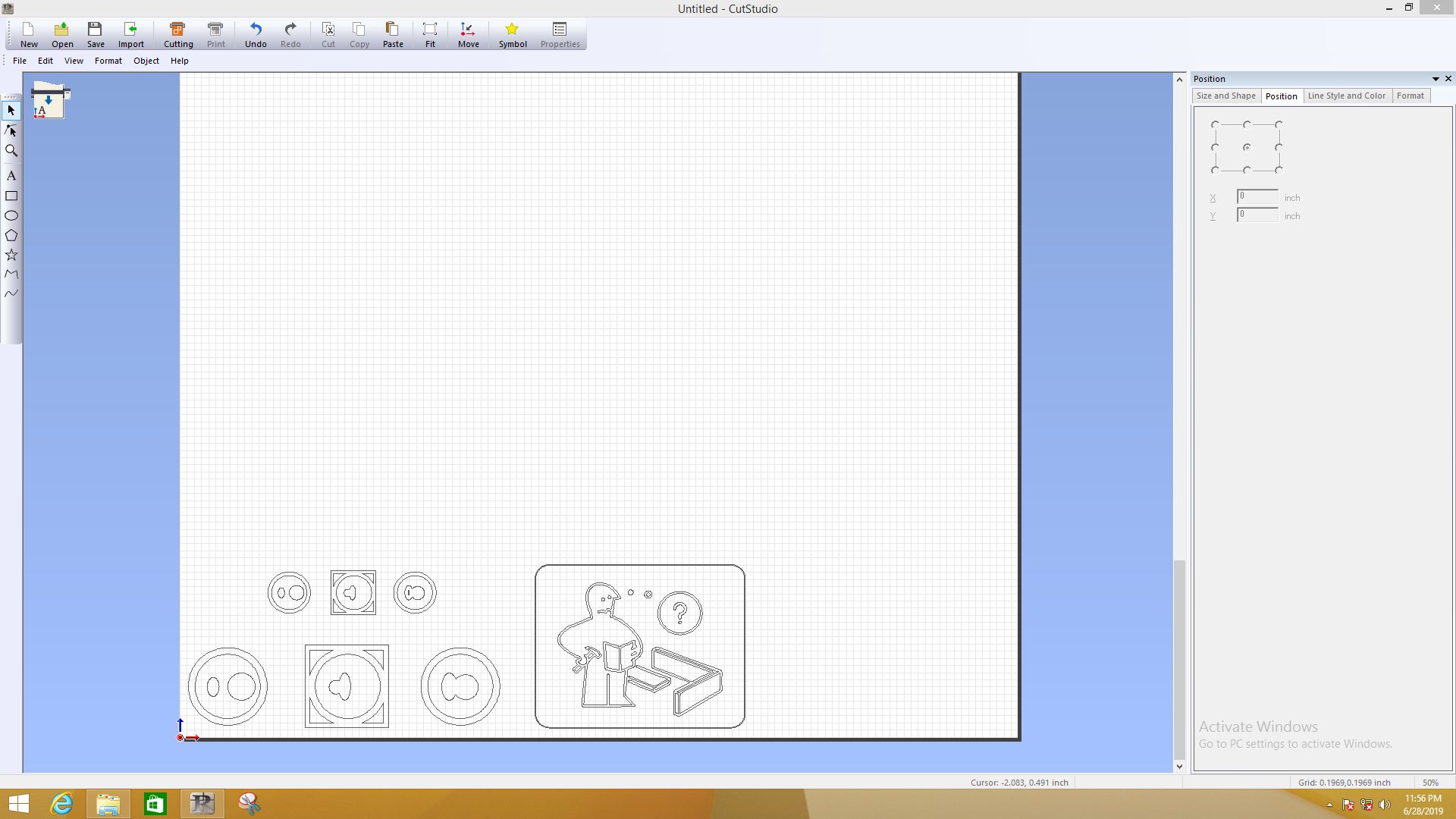
7. Where you position your vector affects the cutting position. Make sure to refer to the origin point.
8. When you are ready, click on Cutting.
Assembly and Result
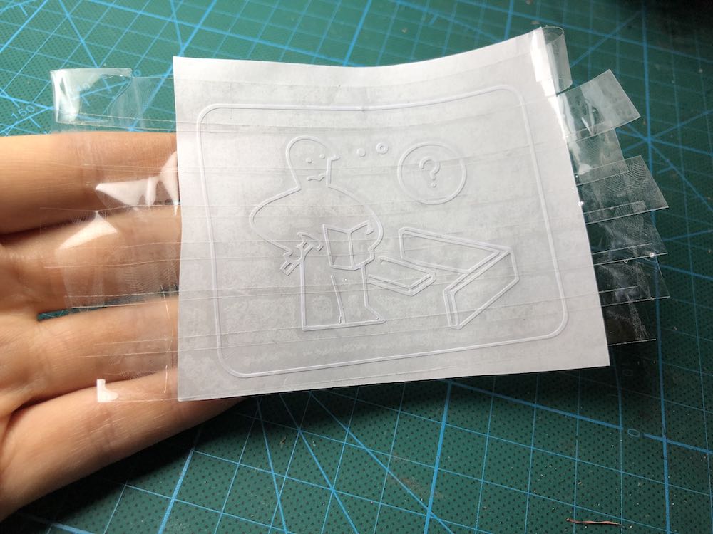
After cutting, I used a tweezer to remove excess stickers. To laminate the sticker onto my box, I used a tape to first remove the sticker from its backing material. Then I pressed the tape onto the box and removed the tape from the sticker.
Here is the final result: