_week 4
computer-controlled cutting
Characterizing FabLab O laser
There are a few types of laser technologies used for laser cutting, the two most common are:
_CO2 Laser (10 micron), widely used and it is the one you will probably find in your Lab.
Among the materials you can use are: wood, acrylic, fabric, paper, leather, glass, certain plastics,
rubber, stone, etc. But you can't cut metal, this is because CO2 lasers operate at 10 micron
and its not enough for cutting metal.
_Fibre Laser Solid State Laser (1 micron), with this type of laser you can cut metal.
The one we will be using at FabLabO is a CO2 laser.
Before using any laser cutting machine you have to prepare your 2D design. While doing your design, as a general rule you have to keep in mind the following:
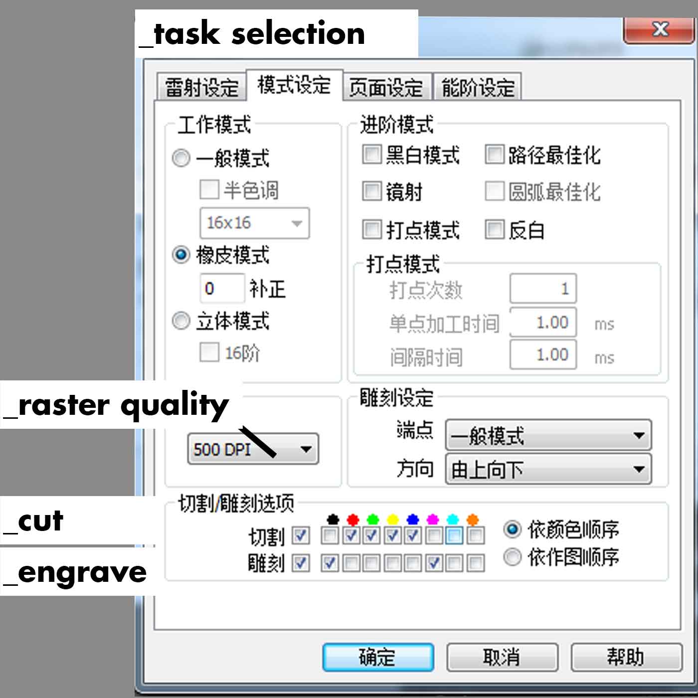
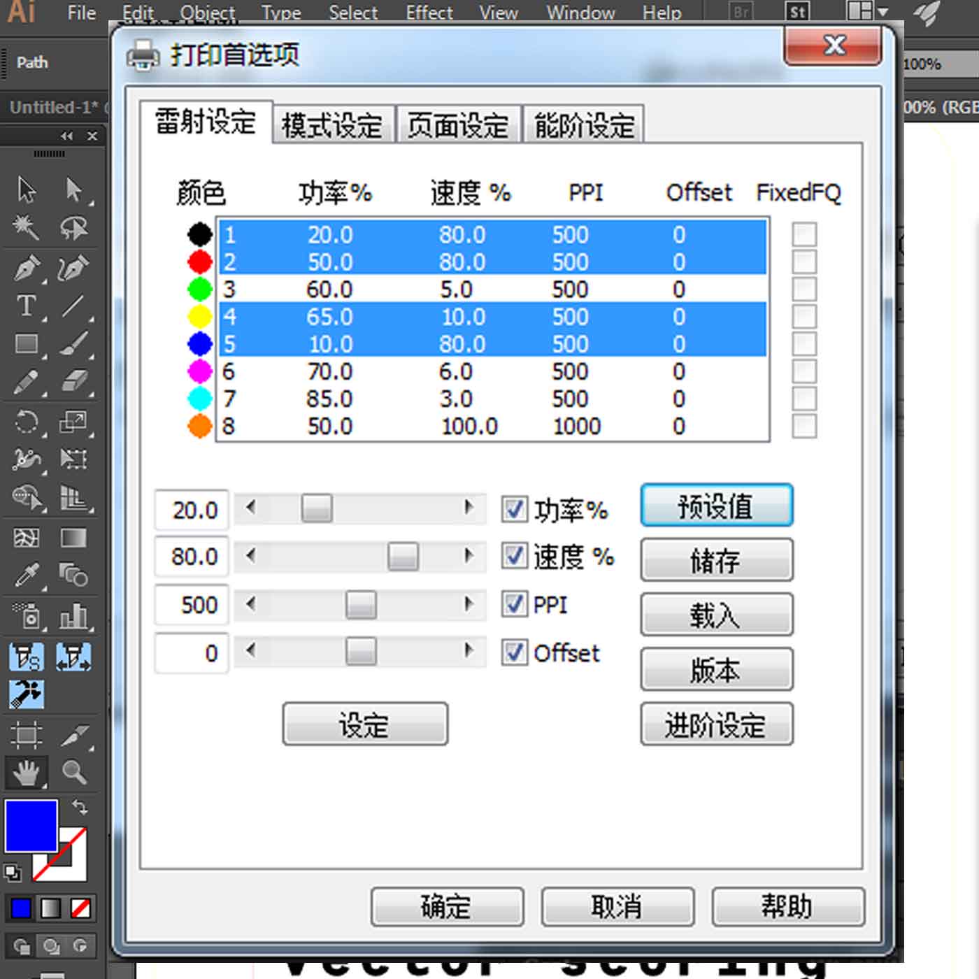
1_Use layers or colors to specify what is a cut and what is going to be engraved (raster engraving or engraving, means the same). In our case we have to use colors (RGB mode) to differentiate the tasks and settings.
2_Line thickness, each machine may vary on this setting, but when you are cutting normally you have to assign a specified value to the lines thickness. In our case it has to be 0.05pt, if you don't use this value the task won't be recognized as a cut and it won't execute it.
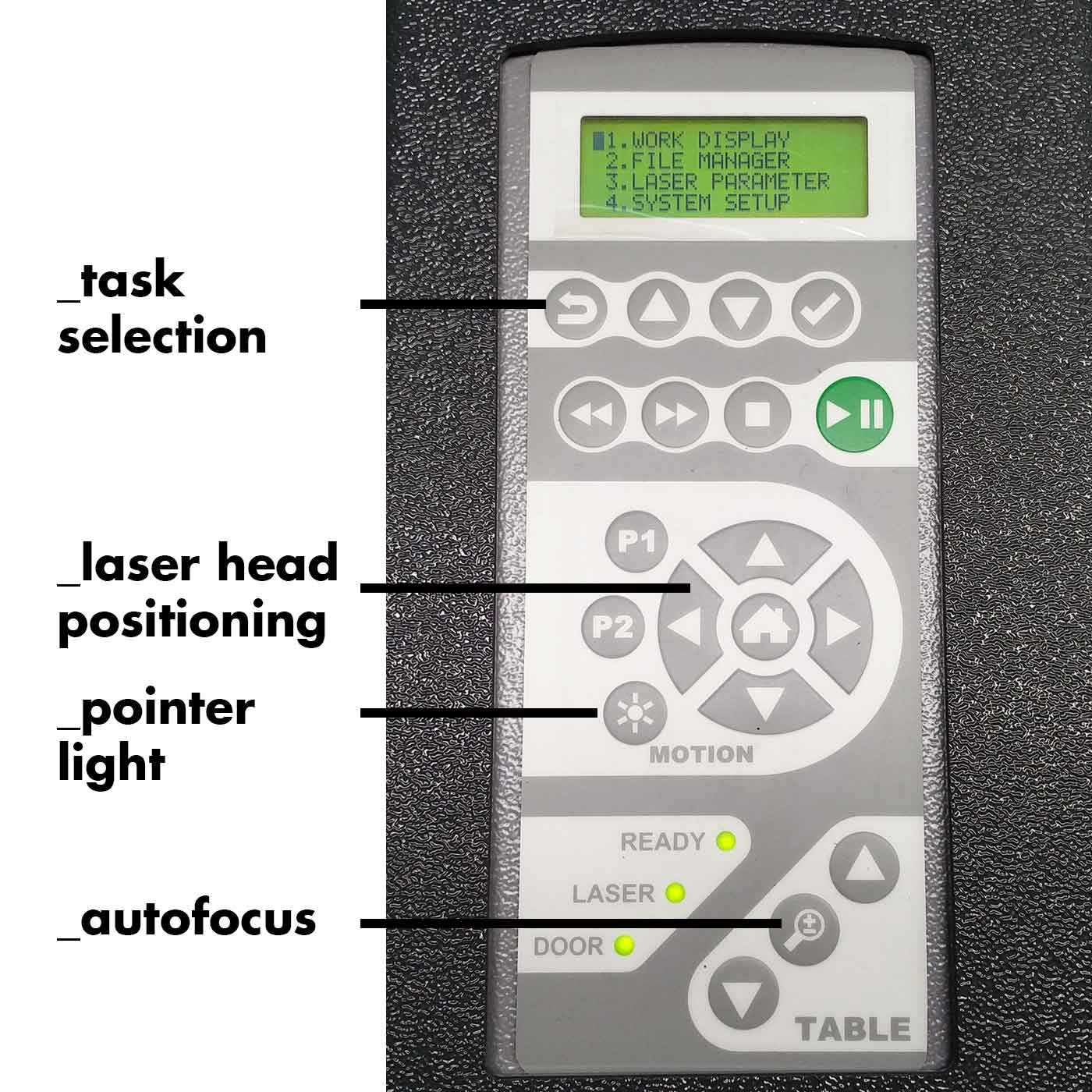
Once you have your files ready to cut you have to prepare the machine, this means you have to check and set up the following:
3_Set the power: basically the power is how much power
the laser
beam outputs. Every machine and every material will vary on this, but you must set the power percentage
either for cut, engrave or vector scoring every time.
4_Set the speed: this speed is how fast the laser head
travels.
Again every machine and every material will vary on this, normally engraving (raster) has to be much
more
faster than a cut.
5_Set the PPI: PPI stands for "pulses per inch", also
refered to
the frequency, this is the pulse rate per linear inch of travel.
After you are familiarized with these terms now we can talk about what type of tasks you can do in a laser cutting machine.
_CUT: cuts throught the material (you need to consider the
KERF, below I will explain what it means)
_RASTER ENGRAVING: material is being removed/burnt but not
enough to cut through. This task takes more time than cutting, so keep in mind the disposition of the
parts of your model in order to optimize the task time.
_VECTOR SCORING: basically this task is like cutting but
with a lower power and faster speed, so that you don't cut through the material. It is recommended to
use this task when you want to engrave simple lines (vectors) with no fill, it will be much faster and
with better results than if you use raster engraving.
What is the KERF?
Kerf refers to the width of the cut of tooling, in other words, it is the gap of the material removed.
And it is a very important factor to take into consideration when doing the design of your models
especially if they have to be assembled.
The laser has a kerf that ranges from 0.08mm-1mm, but this varies on the material and settings you use,
for instance, more power burns away more material.
![]()
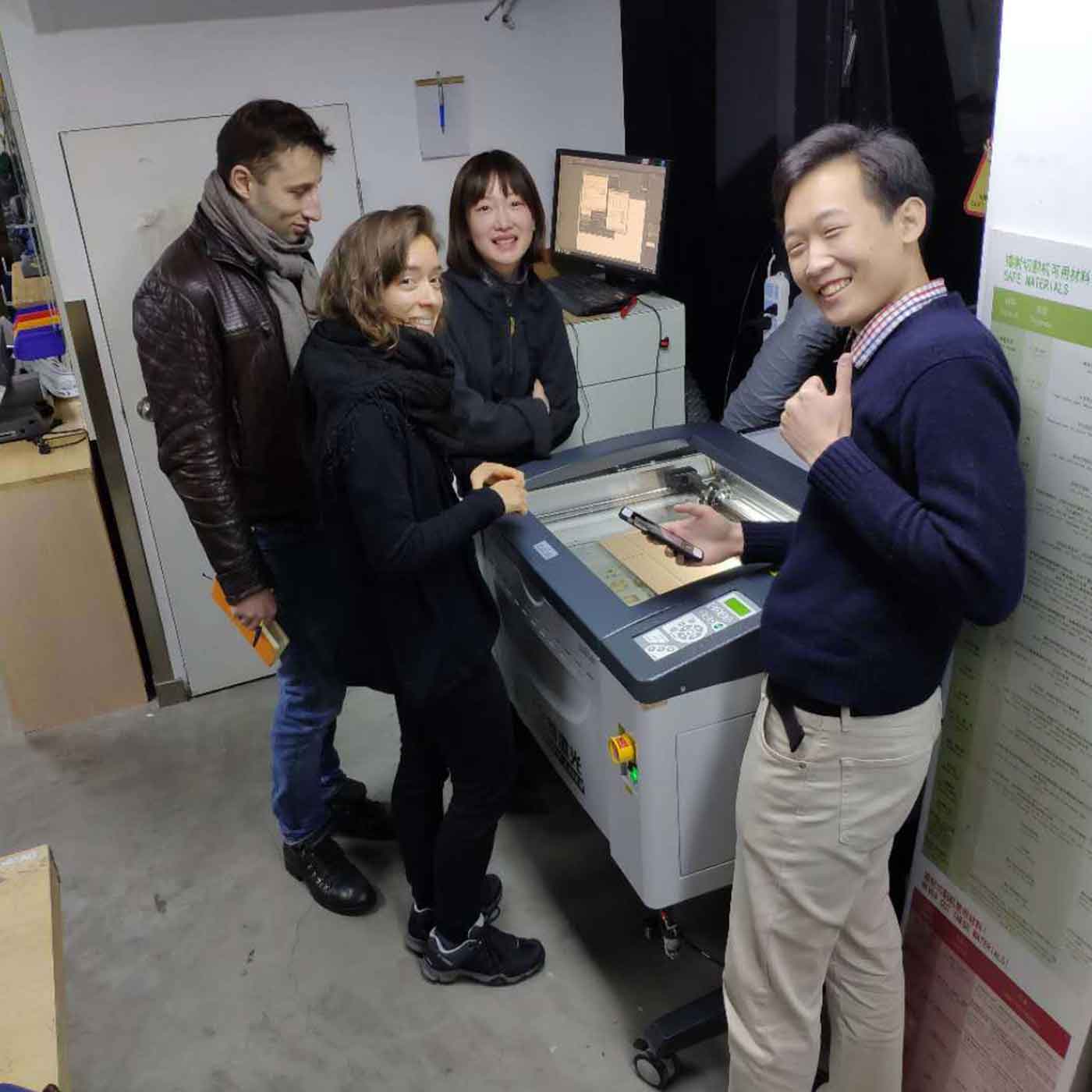
Our group assignment was getting familiarized with the laser we have in our lab, how to set it up, how to cut, engrave and do vector scoring.
For this exercise we used one layer corrugated cardboard of 3mm thickness.
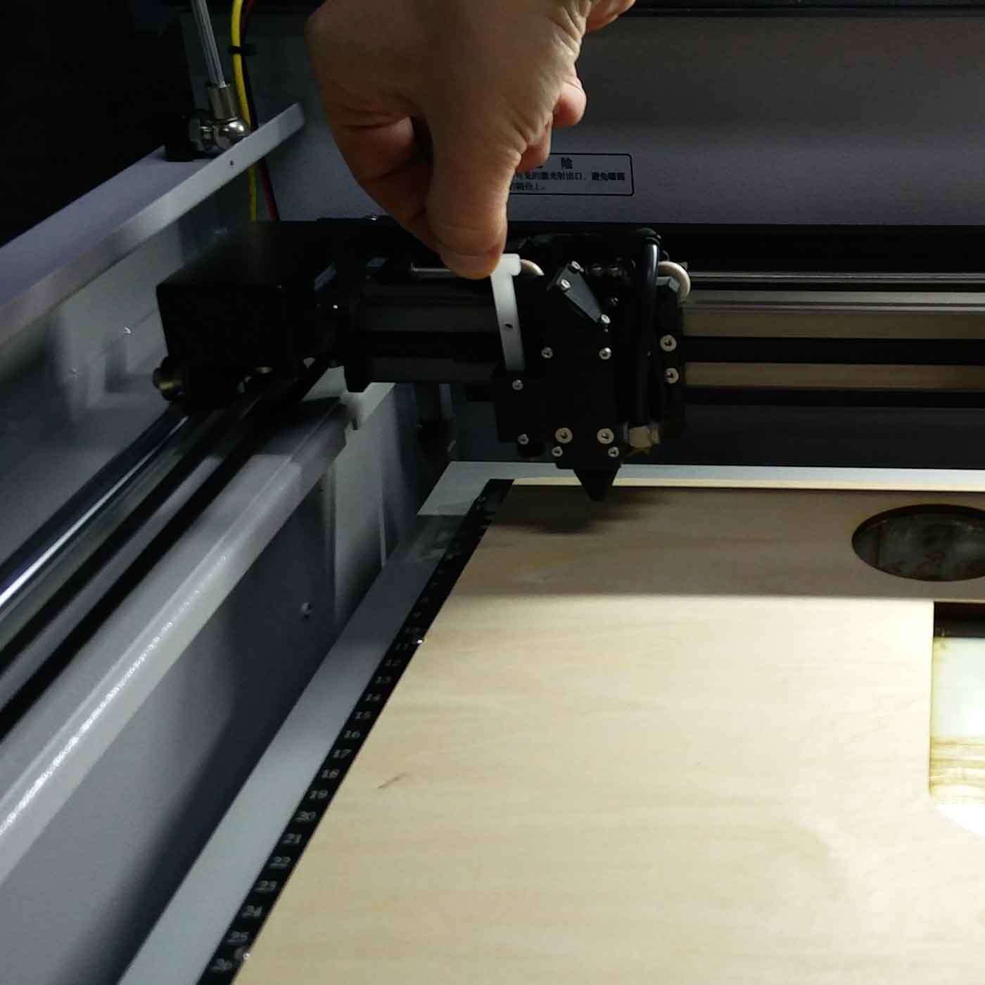
_STEP 1
Calibrate the laser bed:
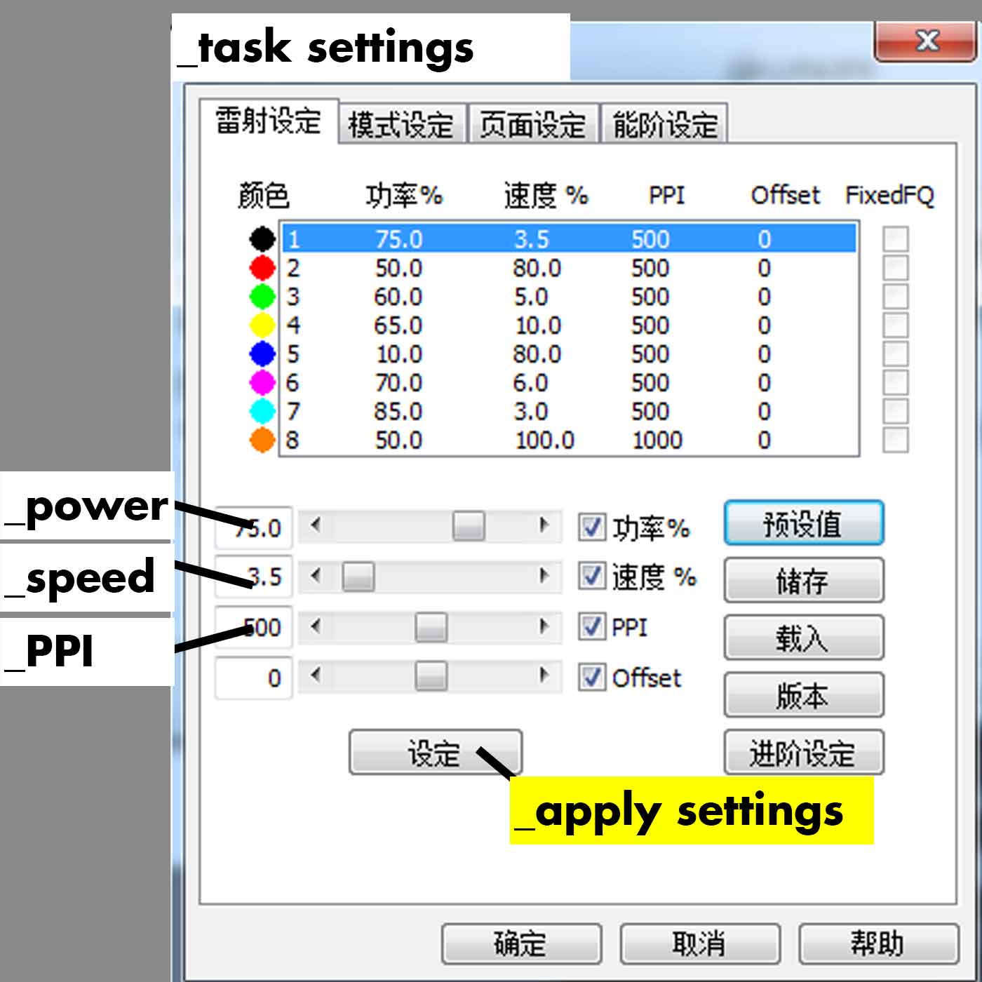
_STEP 2
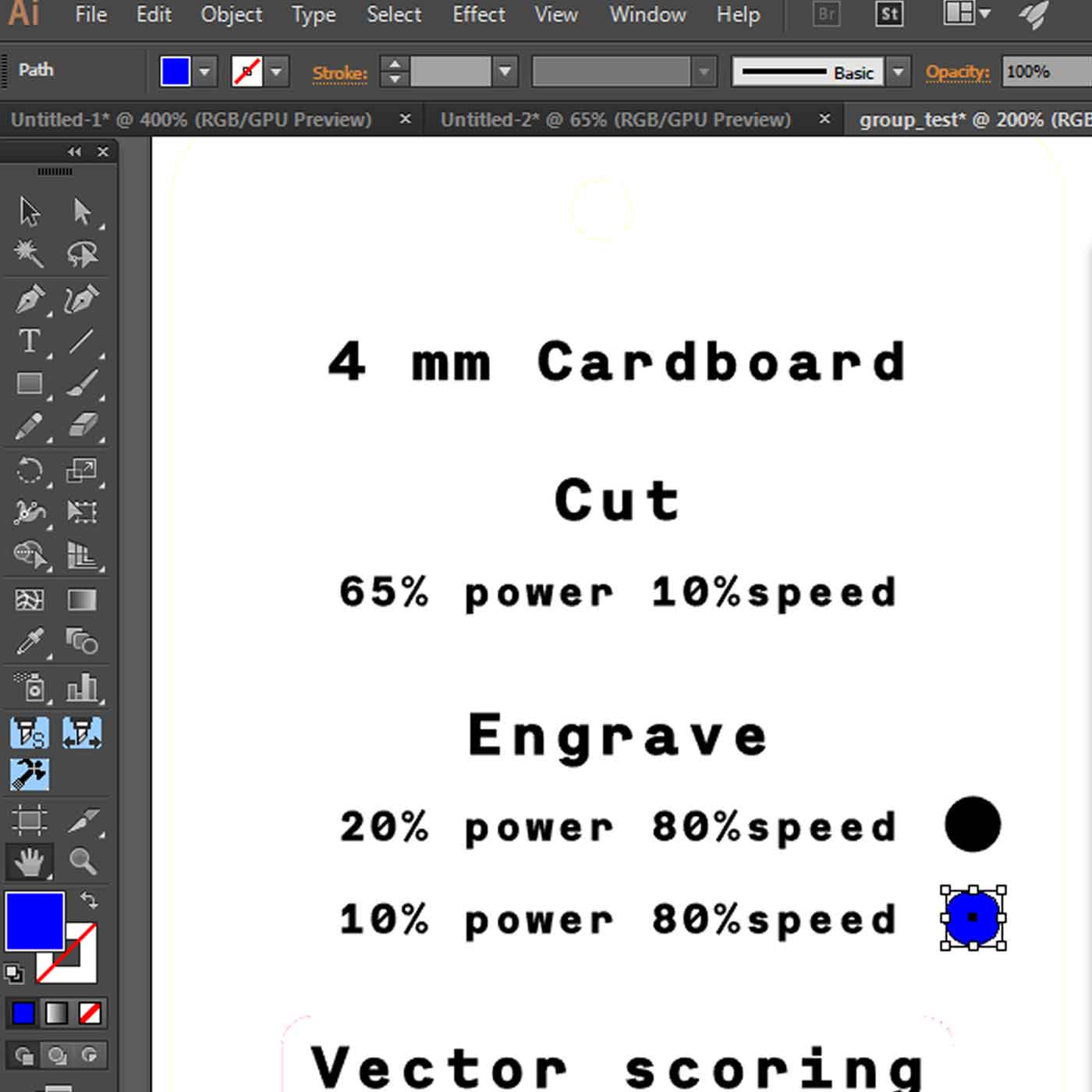
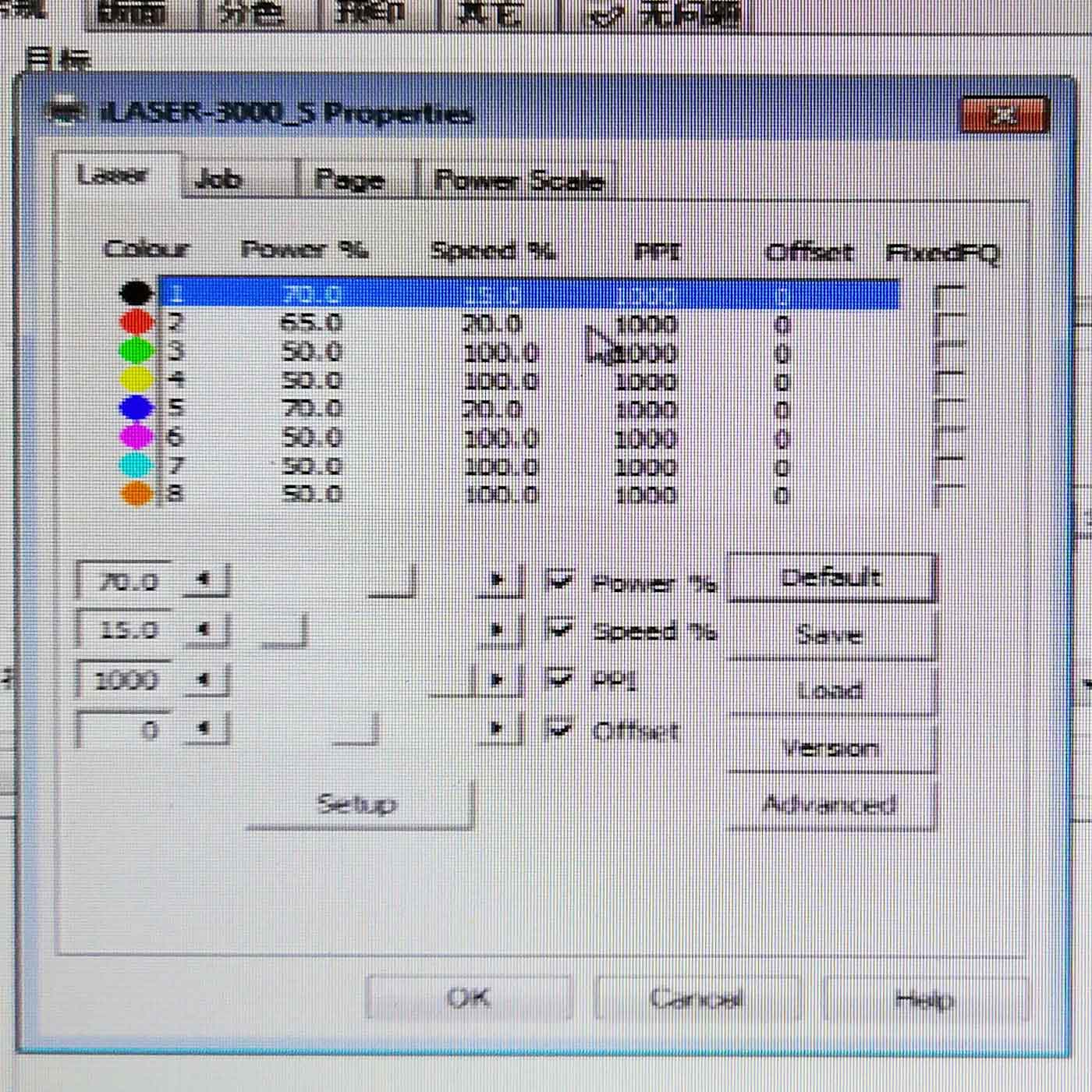
Define the settings for your material. Here we set up a cut, engrave and vector scoring task:
_STEP 3
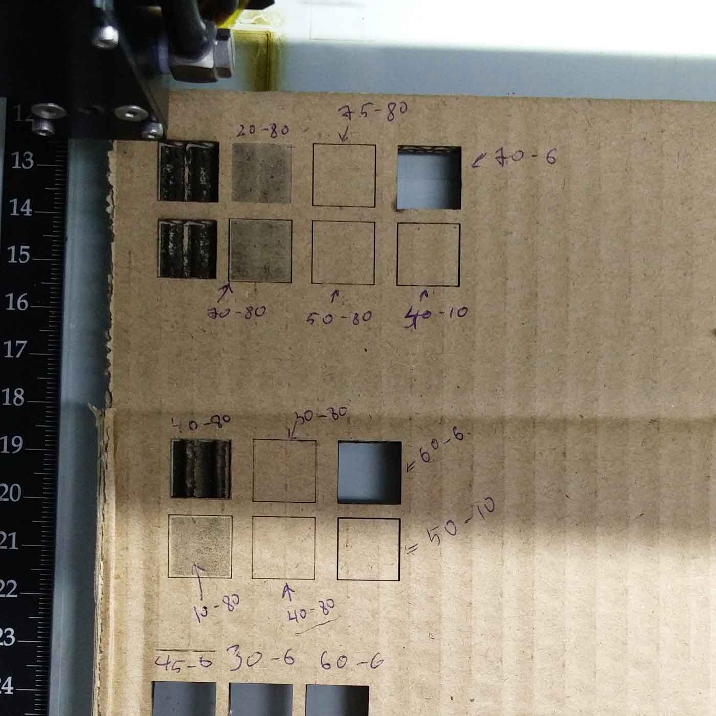
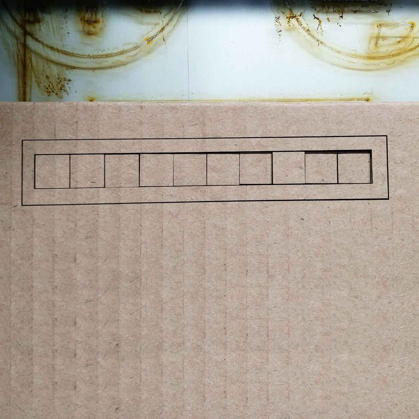
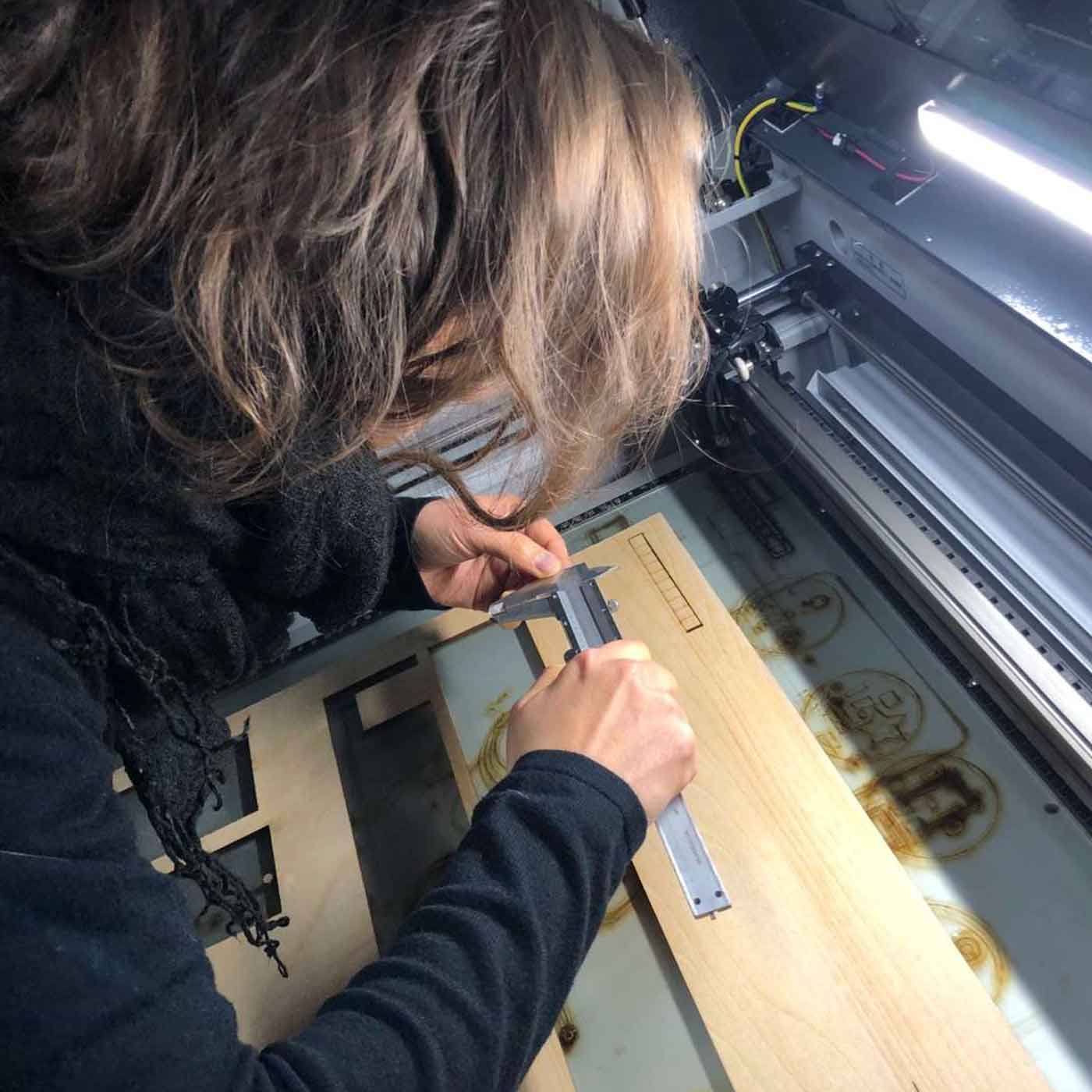
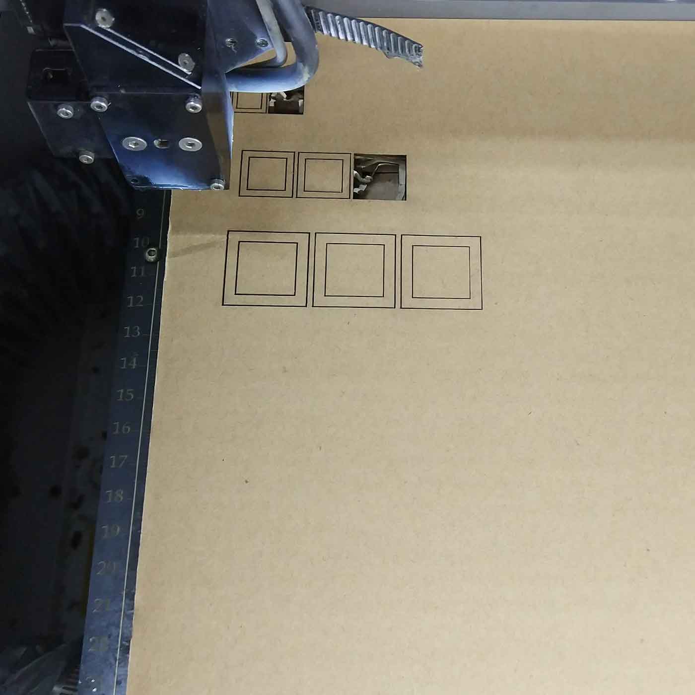
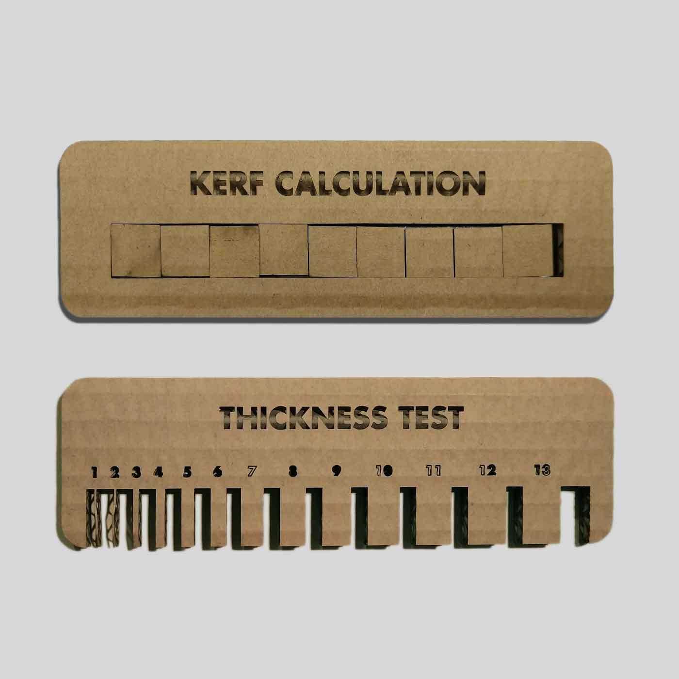
Kerf test, we did a test to understand the kerf of our material. We cut 10 squares of the same size,
then we measured the remaining gap and we divided that value between 10, in order to get an approximate
size of the kerf.
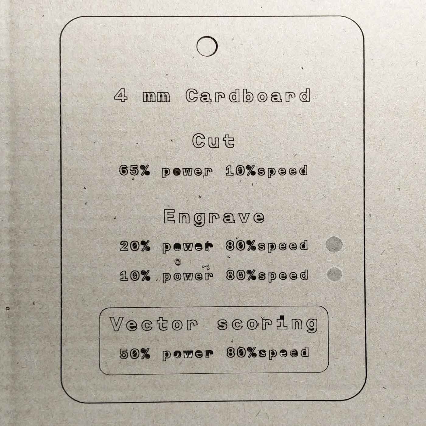
_STEP 4
We created a new information card for the Lab with the settings we of the cardboard we used:
Individual assignment
For this task we had to design and laser cut a press-fit construction kit.
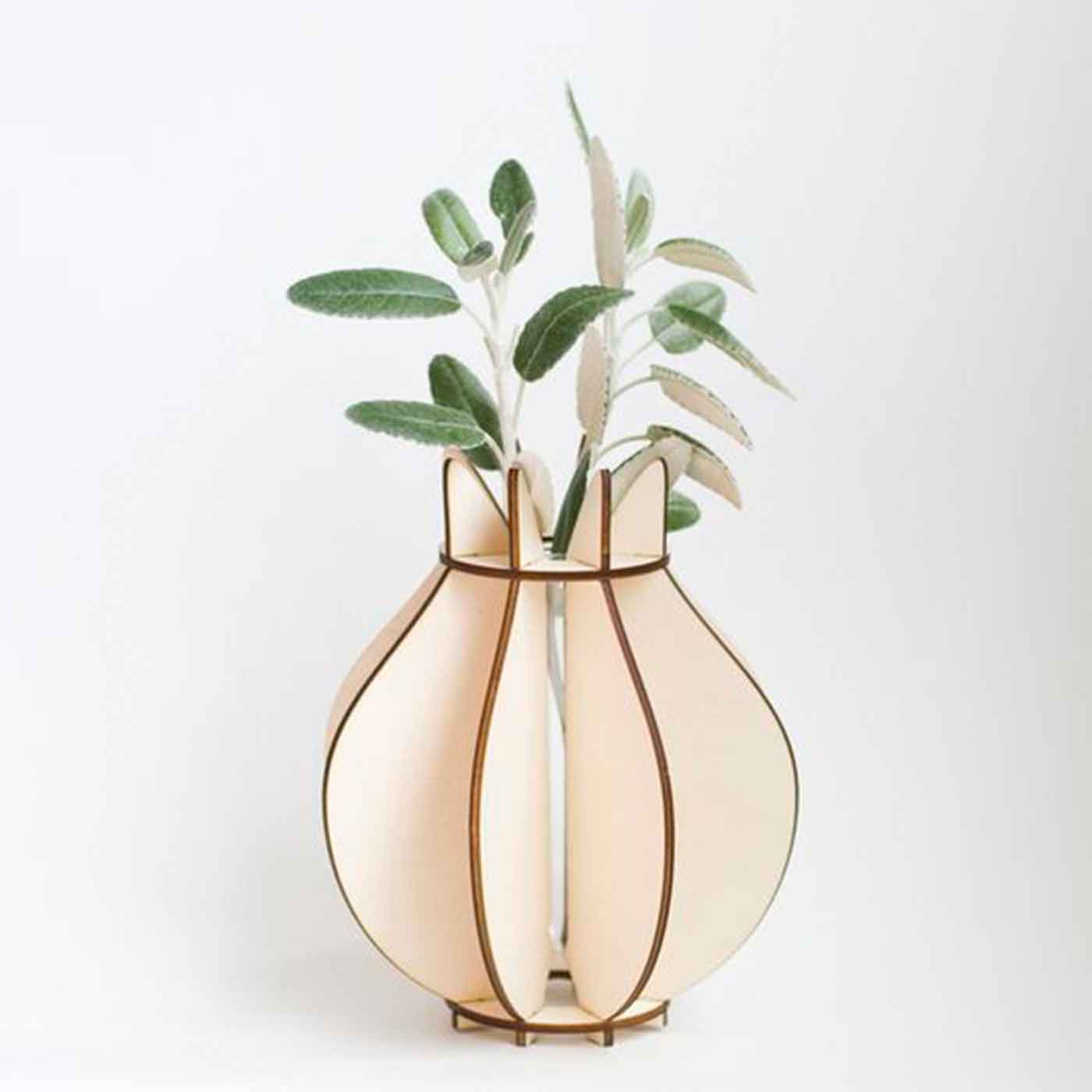
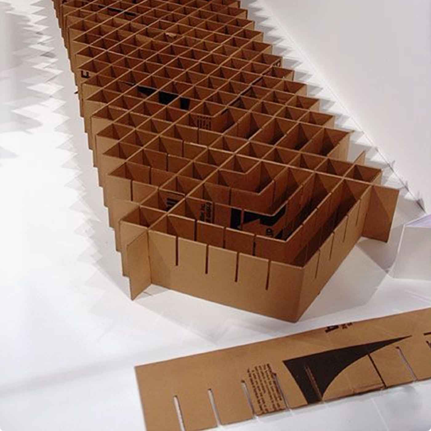
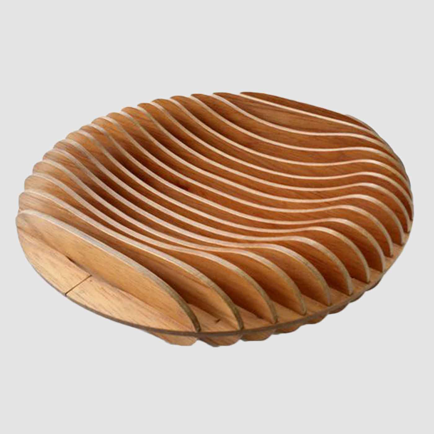
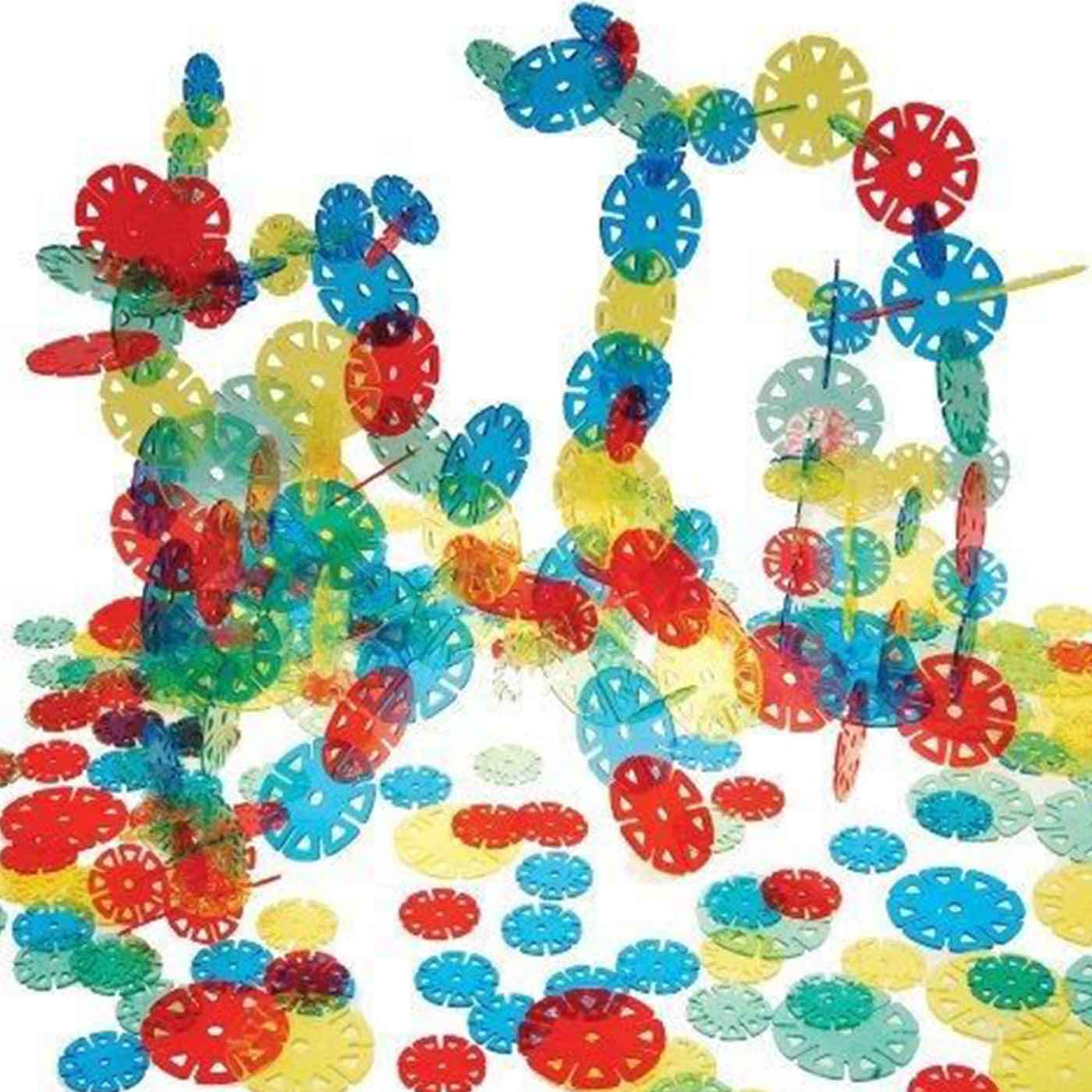
My first approach was doing a research of existing press-fit contruction kits in order to understand how
it works and have some inputs. Here are some interesting designs:
_Inspiration
_Ideas
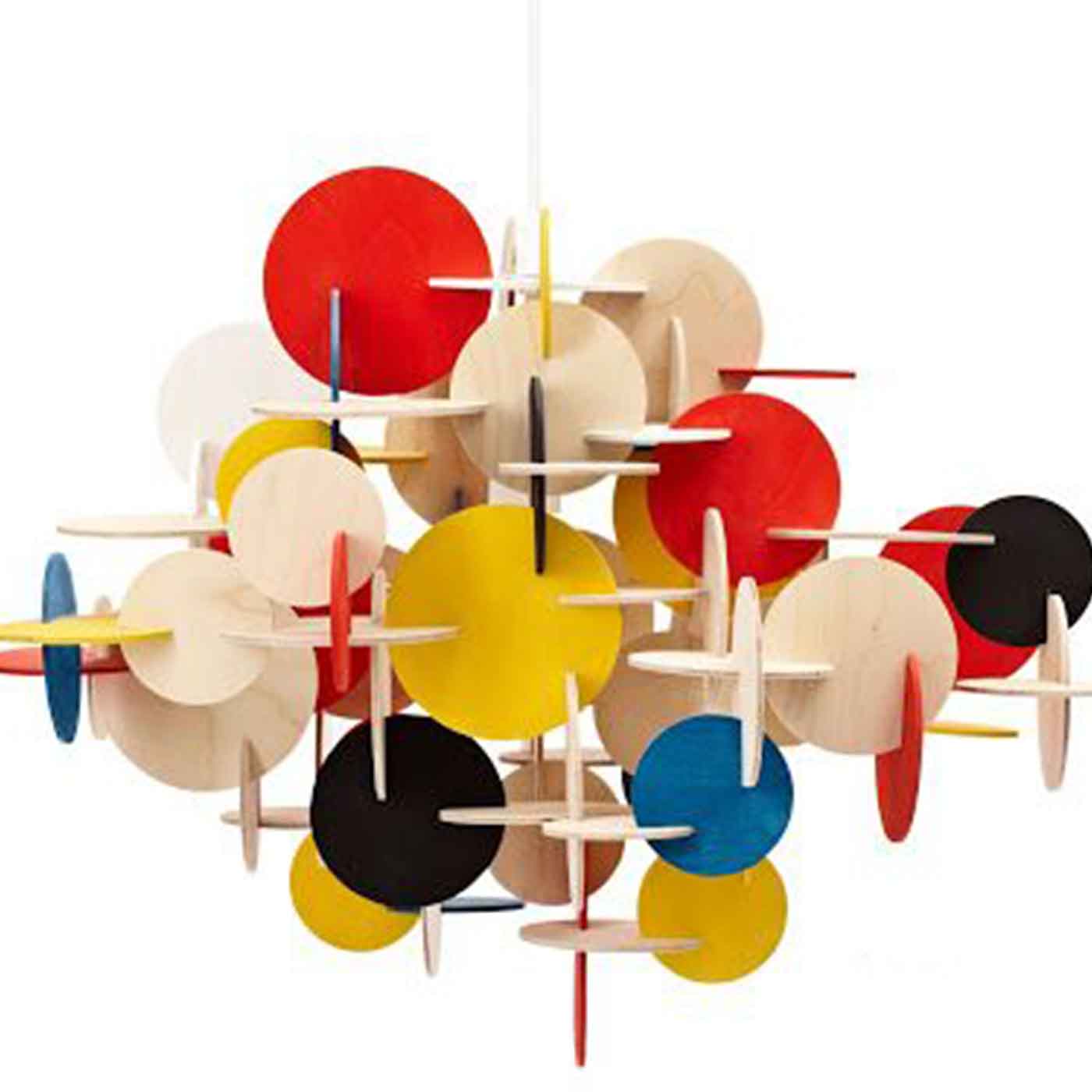
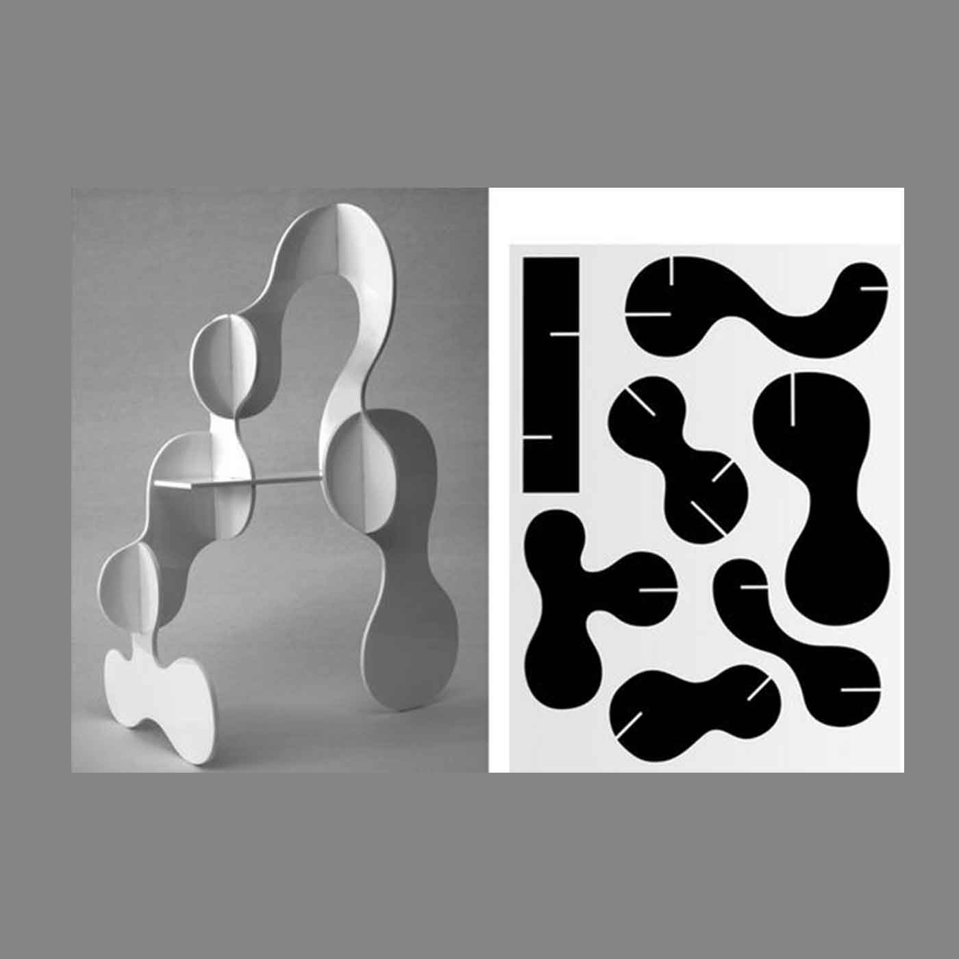
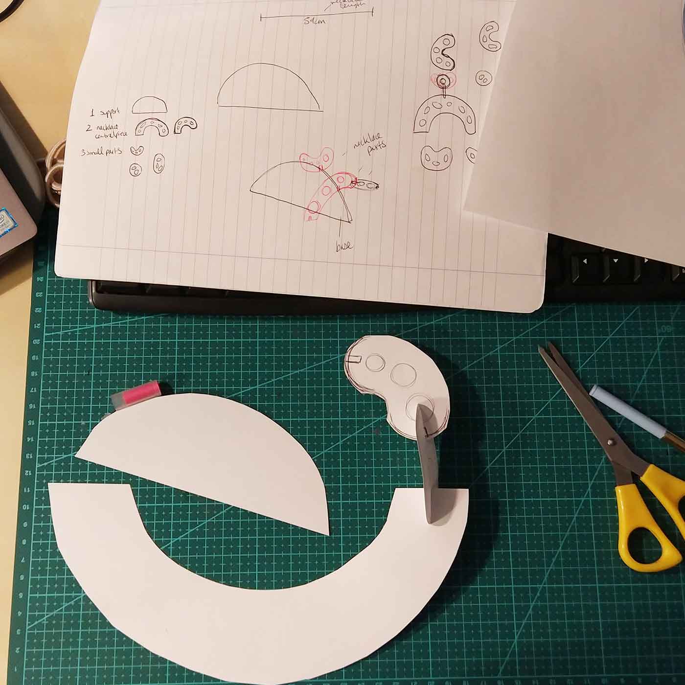
My first idea was to design a jewelry press-fit kit that could be re-assembled to create a sculpture. So when you are not using your necklace or bracelet instead of keeping it on a box or a drawer you reassemble it to create a sculpture that decorates your room.
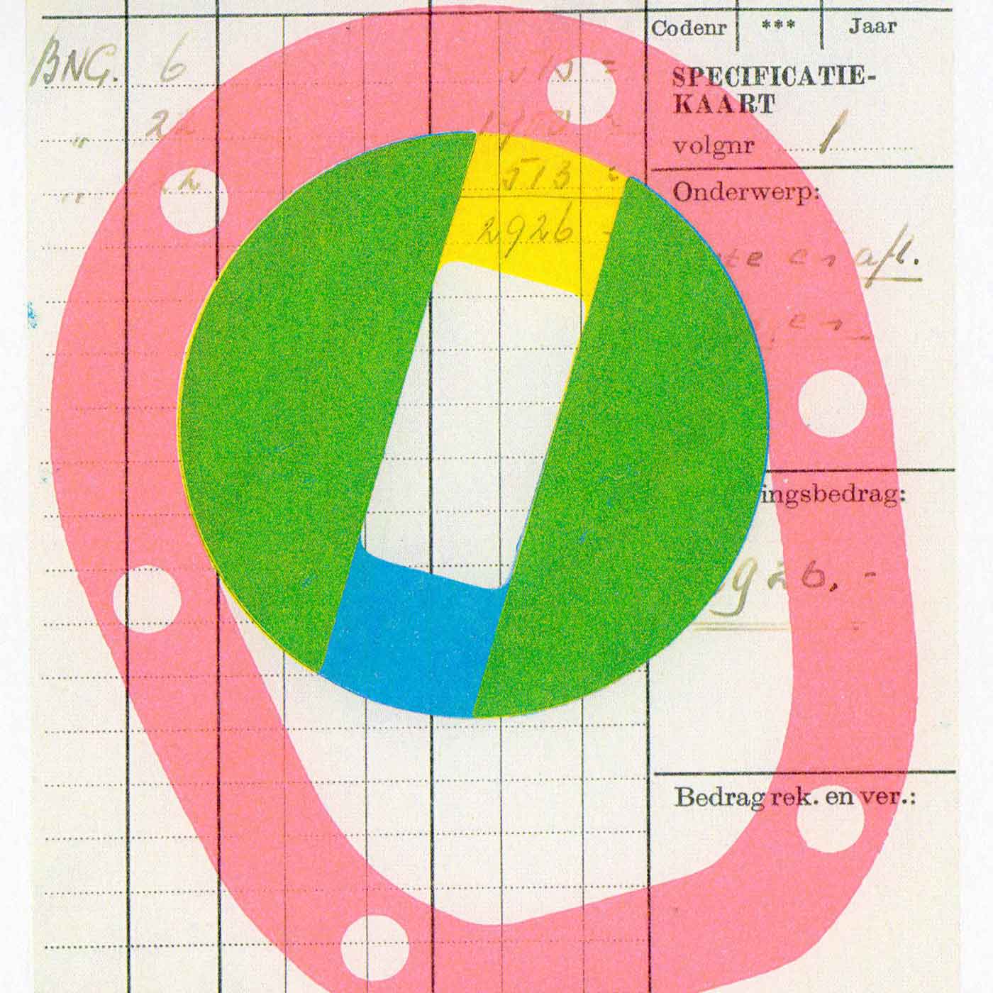
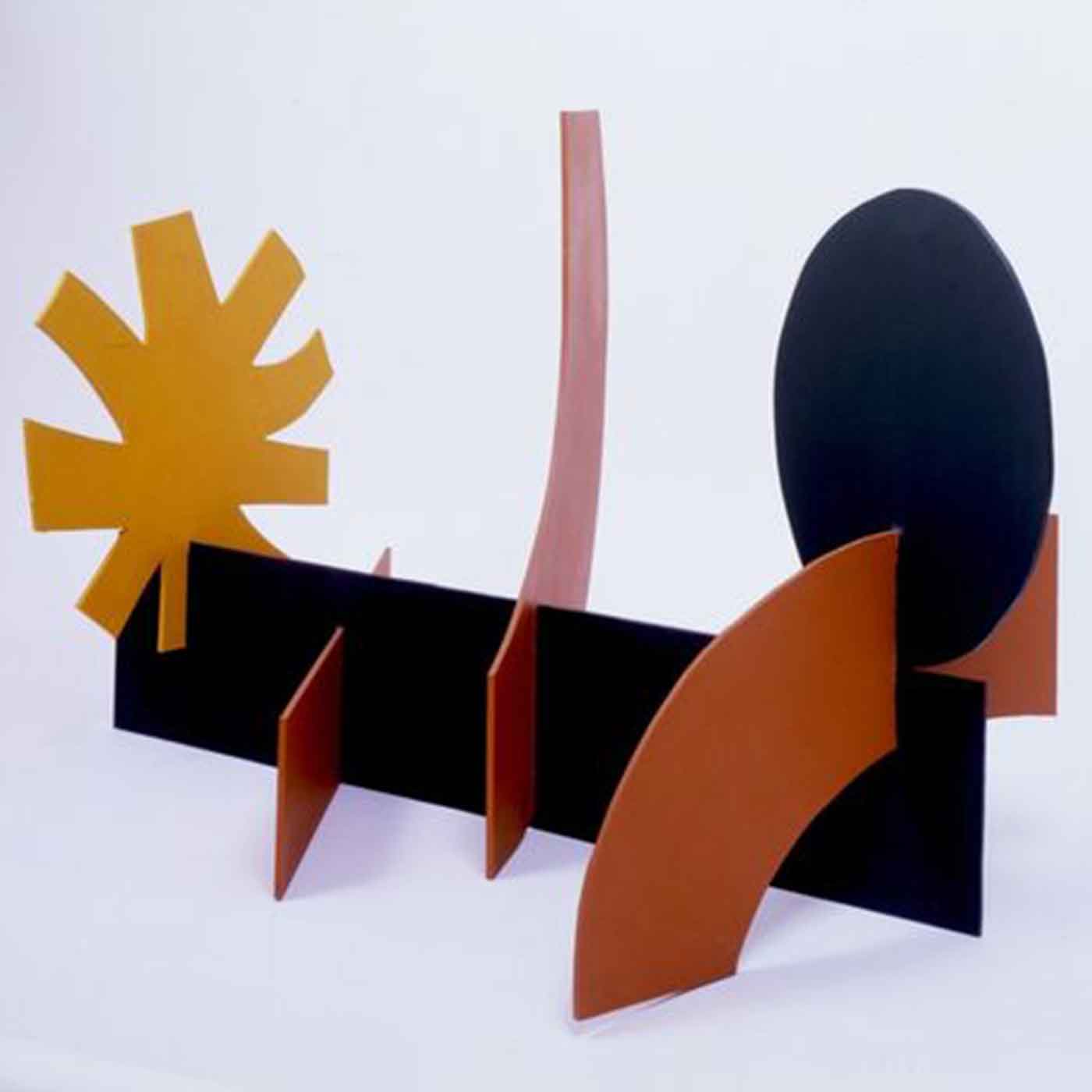
My main inspiration for the design came from two graphic designers I admire their works, one is Karl Nawrot (left) and the second Karel Martens (middle), and Adolph Gottlieb (right) an abstract expressionist painter.
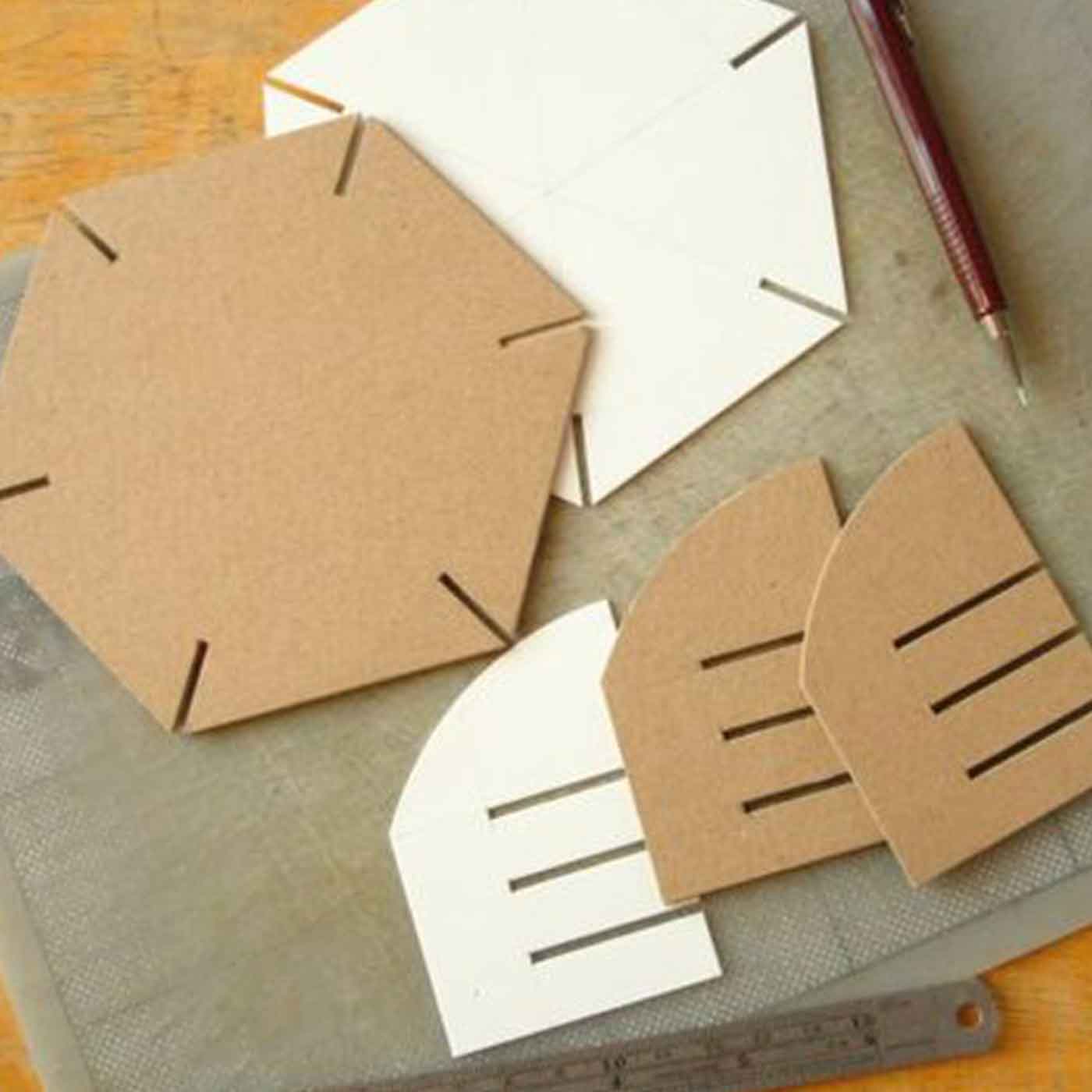
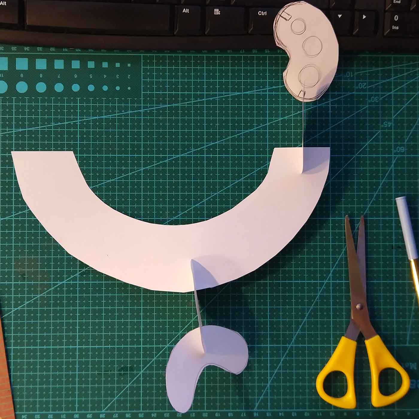
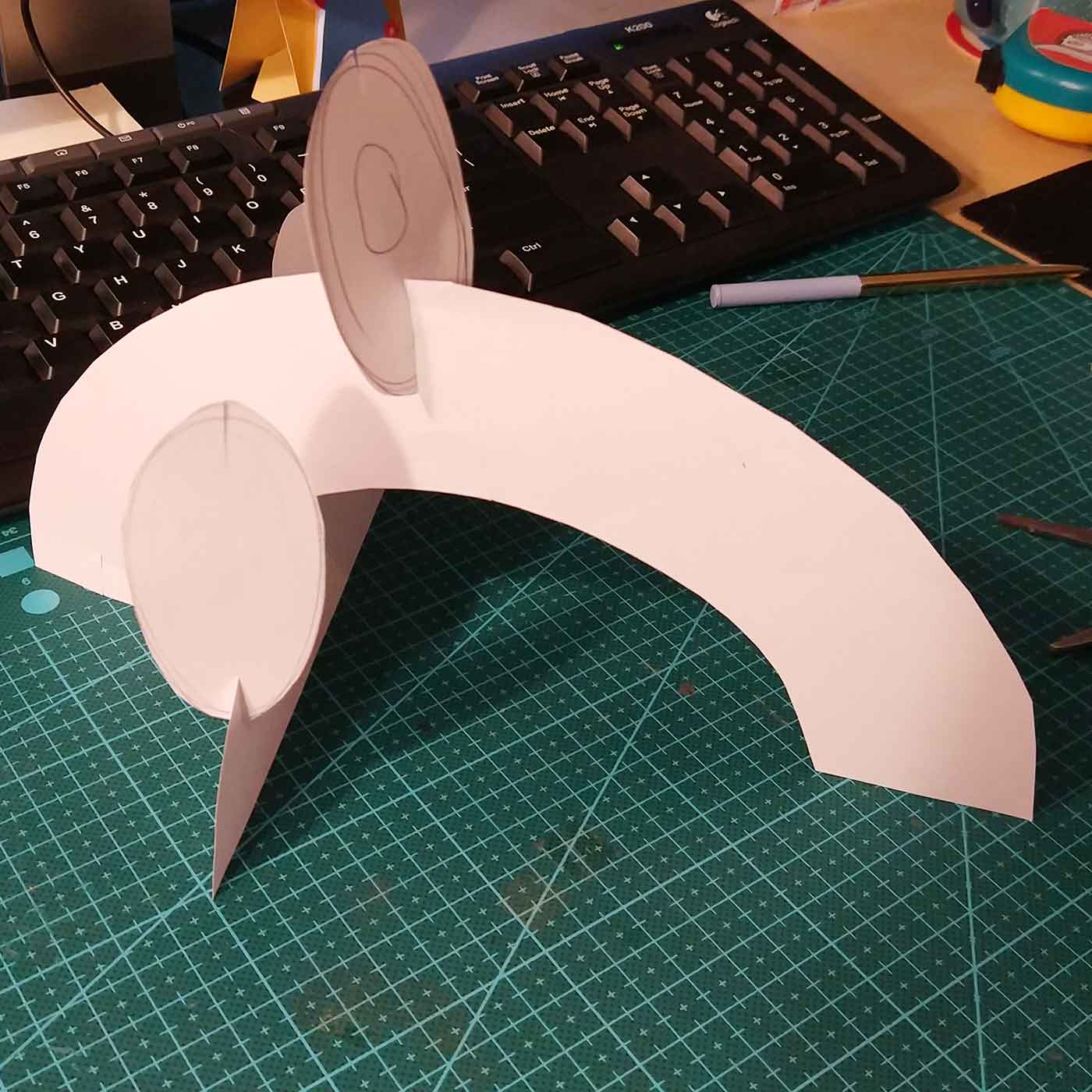
_First prototypes
Originally I thought of doing a necklace, so I started doing some tests in paper trying to understand how many modules I needed and how to assemble them:
_2D & 3D model
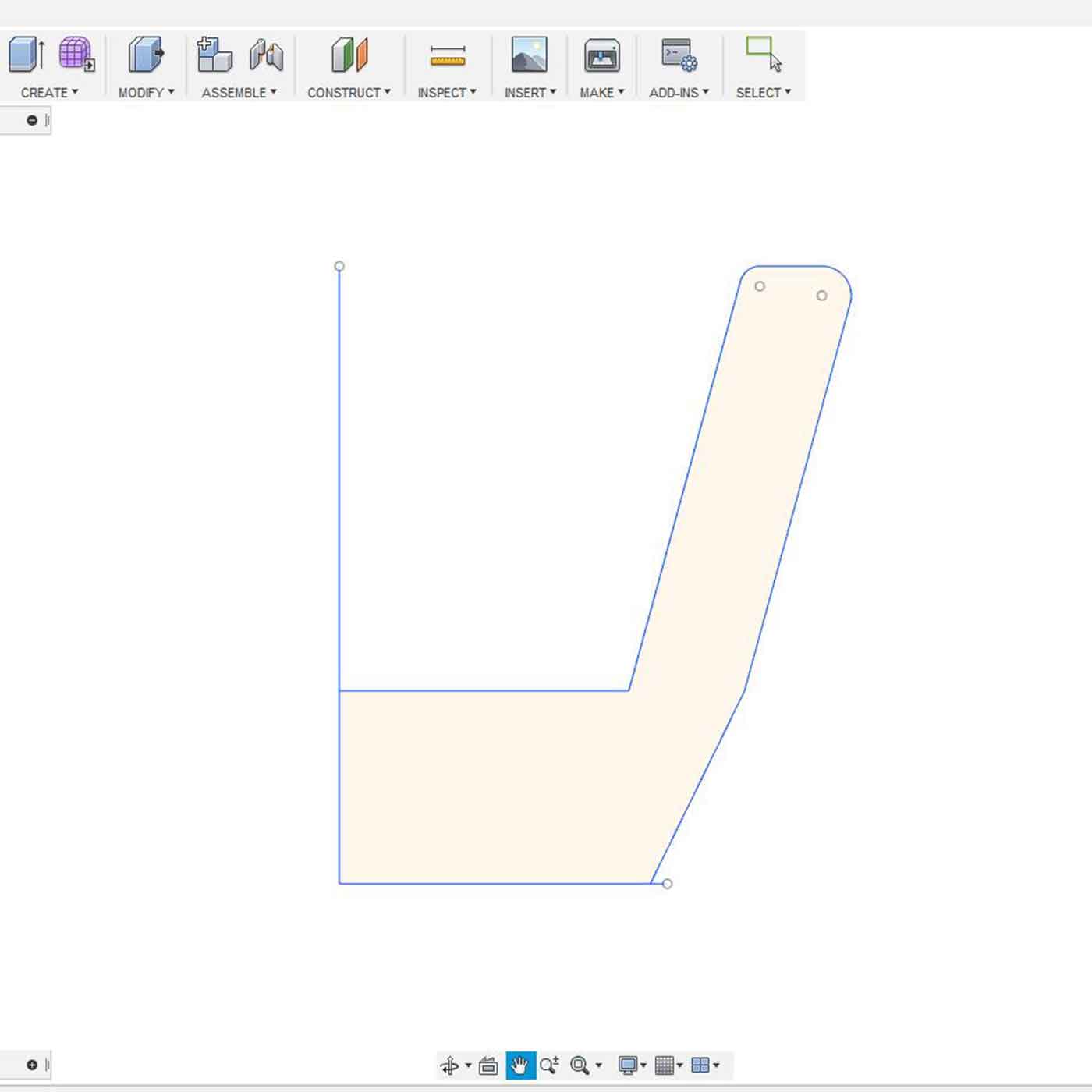
Once I had my 3 modules defined I started building my model in Fusion 360.
I used sketch tool to draw the first module:
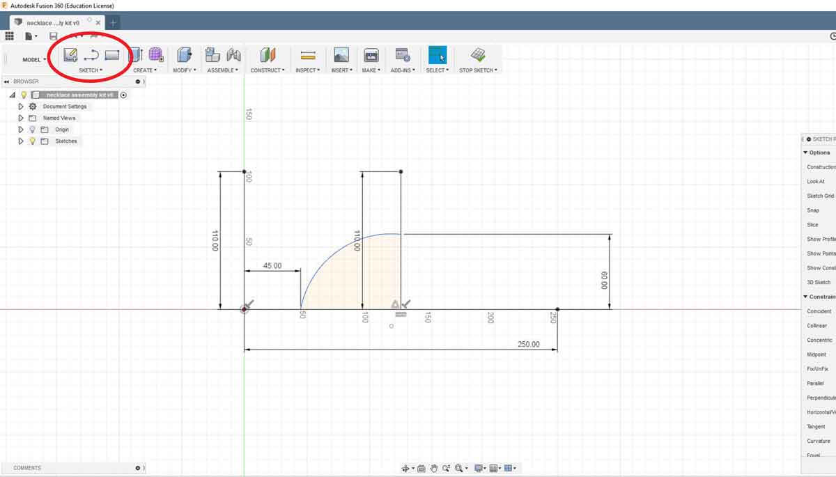
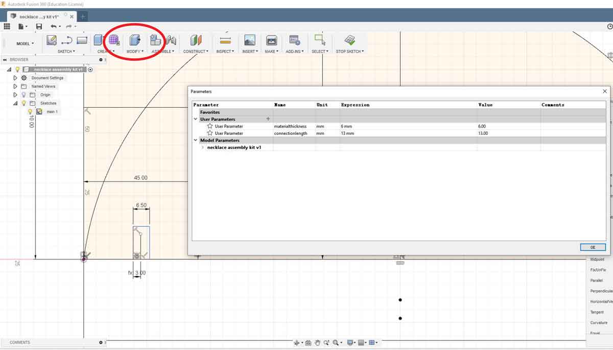
I then set up the parameters of the assembly joints, in this case as I was using cardboard thick 6.4mm, so I started with a parameter of 6mm to try the first prototype.
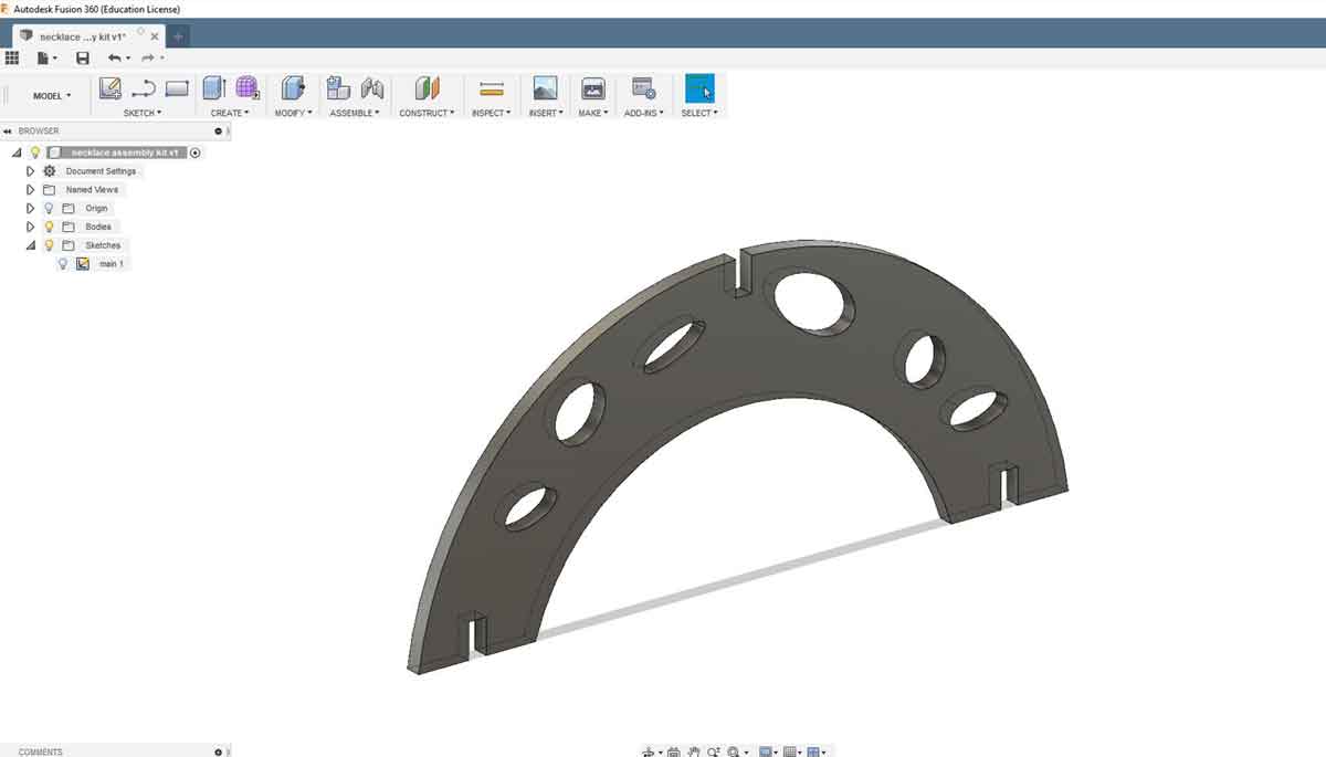
But I then quickly realized a necklace would be too big so I decided to resize the modules and create a bracelet instead:
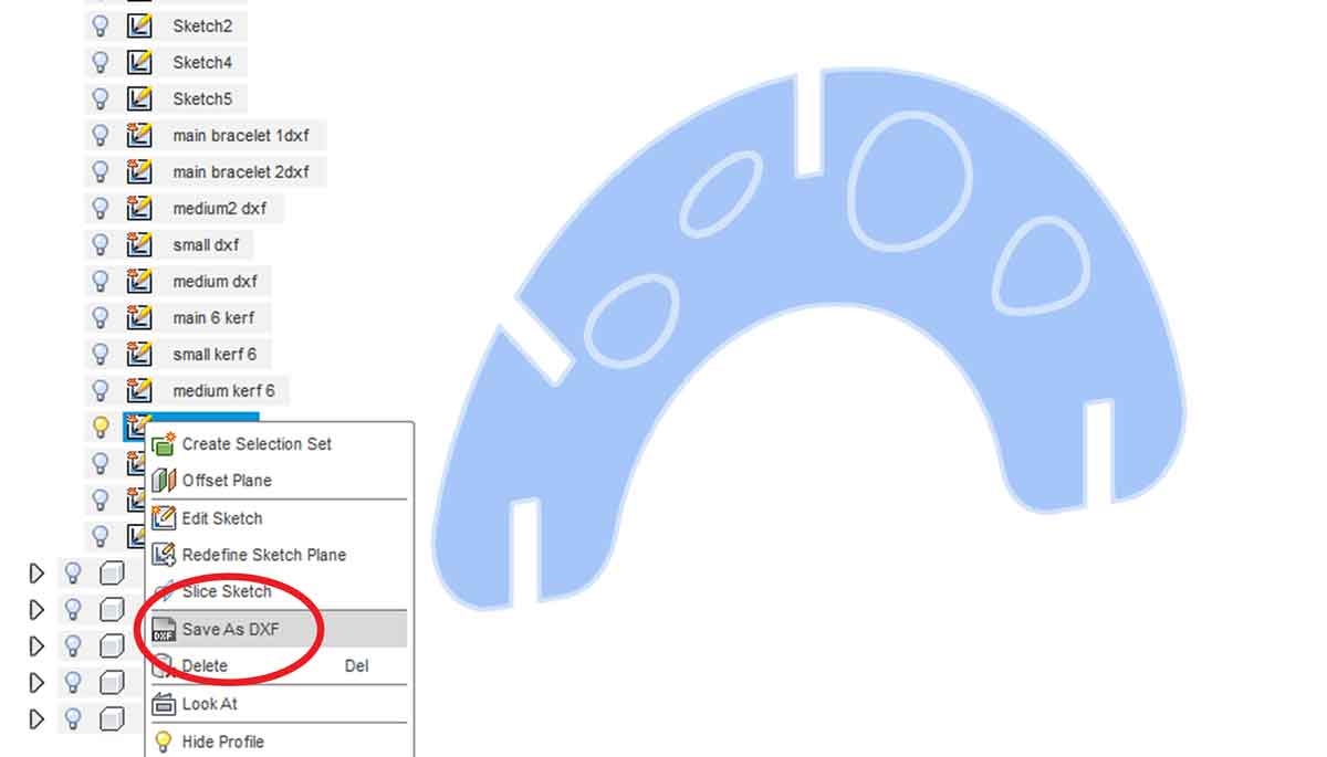
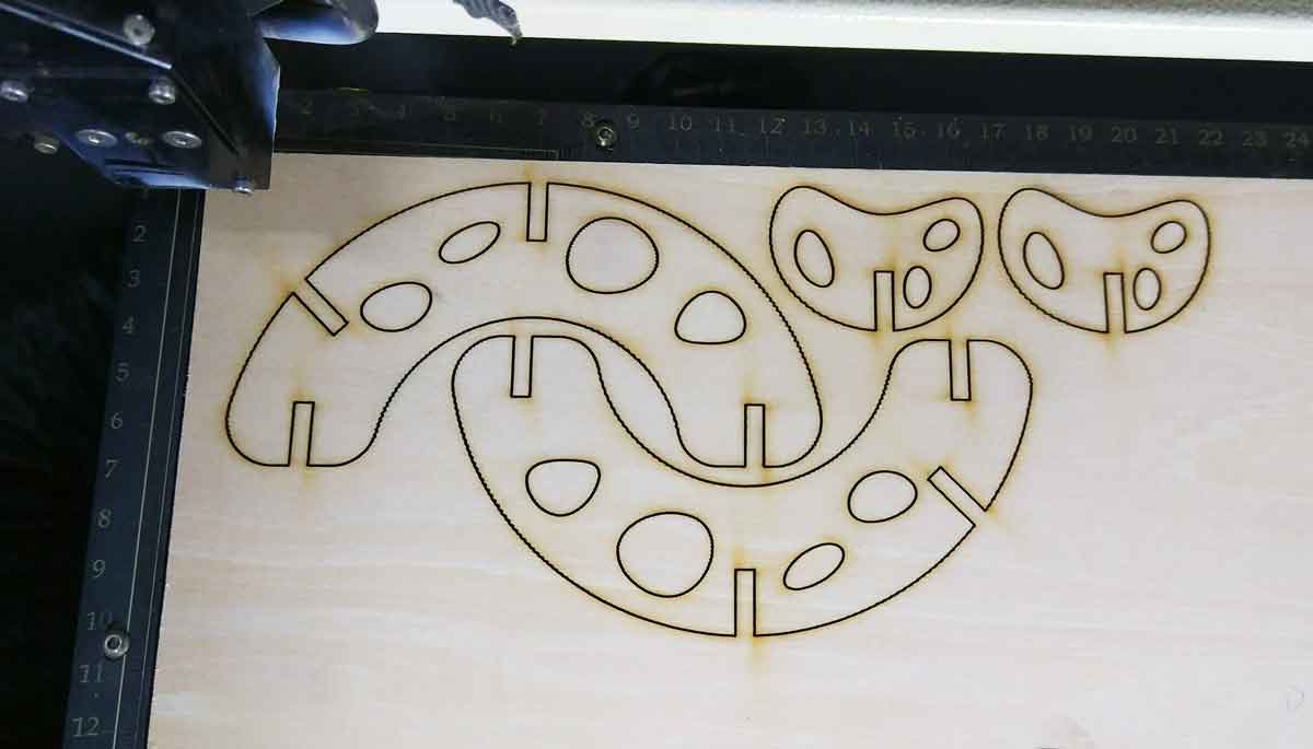
Once I had the modules and the parameters set up I exorted the 3 modules as DXF so that I could open the vectors in Illustrator in order to cut them in the laser. You have to open the sketch layer right click with the mouse and select SAVE AS DXF:
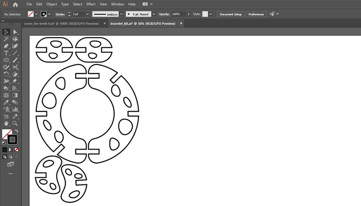
I then opened the DXF files in Adobe Illustrator and I otganized the 3 modules in 1 page and I copied twice each element. Then I set the line thickness to 0.05pt.
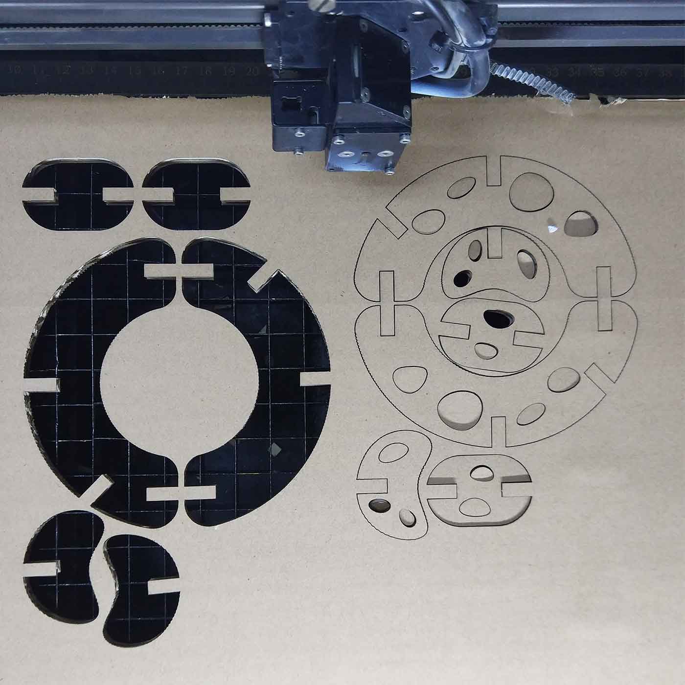
_laser cutting tests
Once I had my file ready for laser cutting I did some tests using the 6.4mm cardboard I was
provided, in order to understand what was the kerf.
1_Firts I calibrated the bed
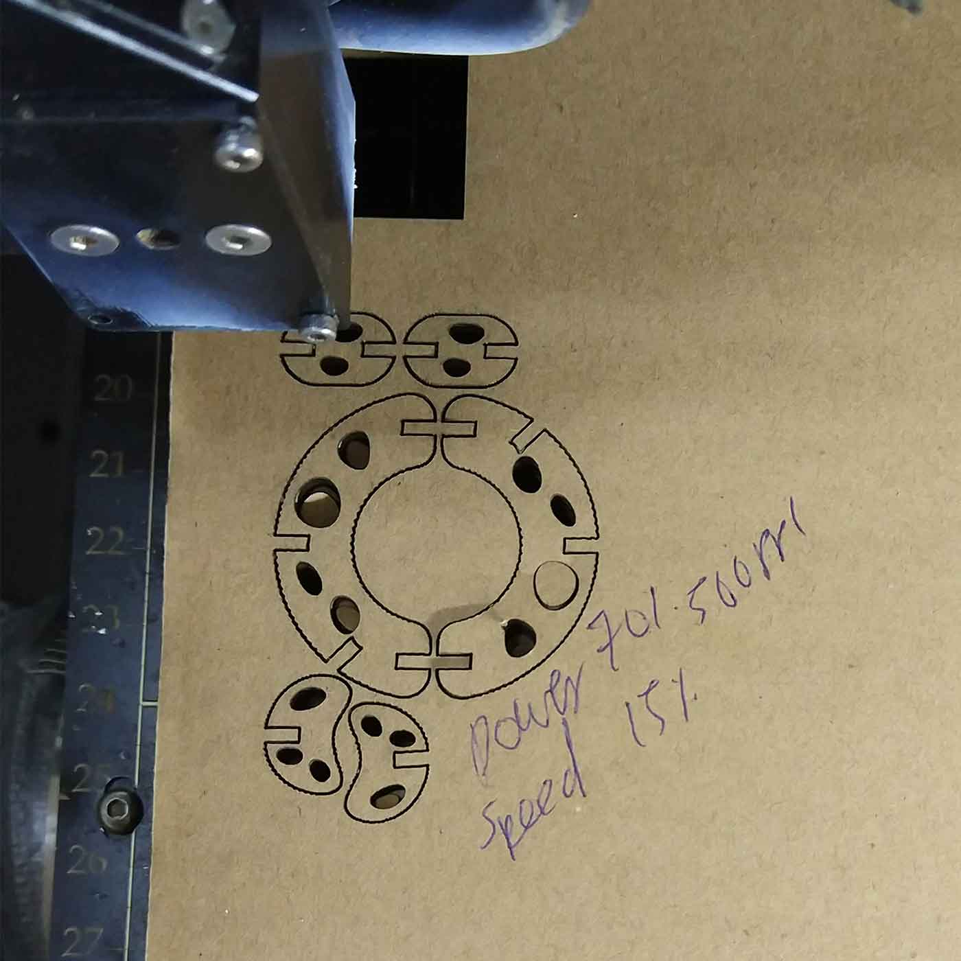
2_I tried out different settings to understand which setting was the best for cutting.
3_Once I had the settings I did a kerf and thickness test.
4_After that I did the first sample of the bracelet. I had to do several tests changing the
joints size.
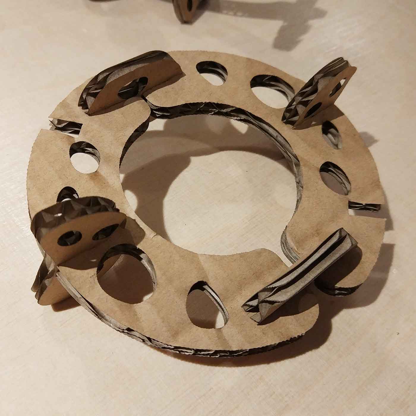
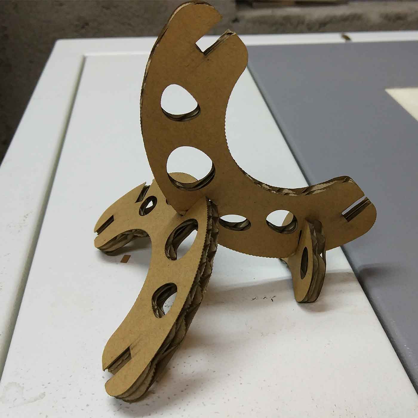
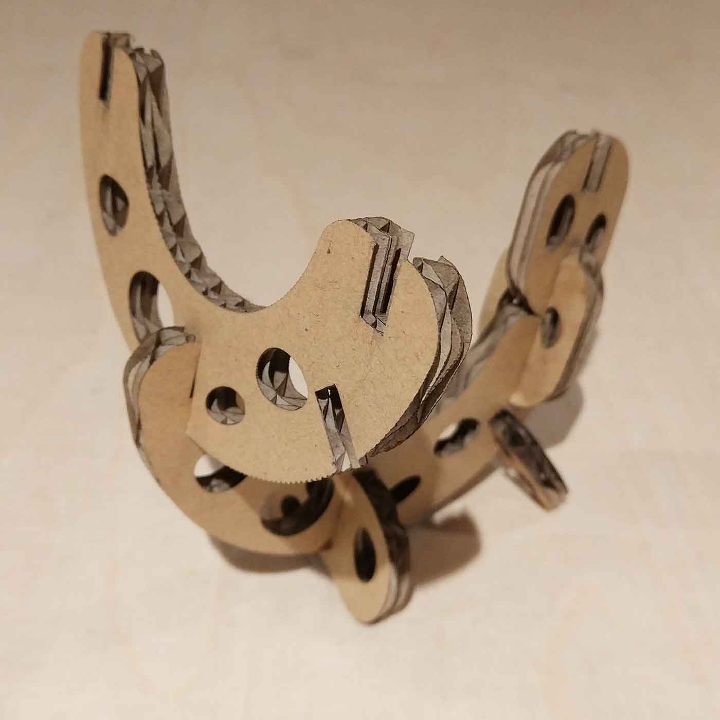
_First outcome
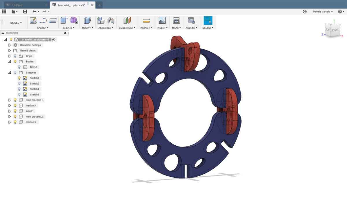
The first models in cardboard worked out pretty well, and I played with the prototype doing some variations of how to re-assemble the bracelet in order to create two different sculptures. Here are the results:
_Second outcome
After that first attempt in cardboard I did a test in plywood as after a while the cardboard
joints started to break down.
So I used the same process as earlier to find out the settings to cut plywood of 3.8mm
After the second attempt, this gave me an idea of how to storage my model, and I decided to create a packaging to present the design and to take it back home.
_Packaging for transportation
Imagining that this was a real product, I thought of doing a packging to transport and storage
the bracelet-sculpture press-fit construction kit.
Using some cardboard leftovers I designed a simpler container that is basically an offset of the
modules organized in a way so that the space is optimazed and minimized.
_Animation stop-motion
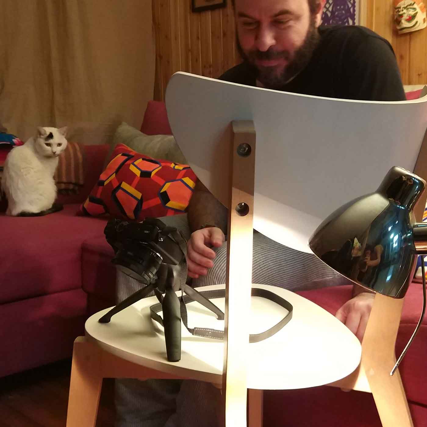
I thought the best way to share the concept of this design was doing a stop-motion video.
I asked for advice on which was the best way to do it and how to do it to the best Video Editor in
town, my boyfriend Jose Salto.
Together we did this stop motion and we had lot of fun doing it.
I will explain later the behinds scene how we did it.
This is the process of how we did the stop motion.
1_First we set up a small stage to take the photos.
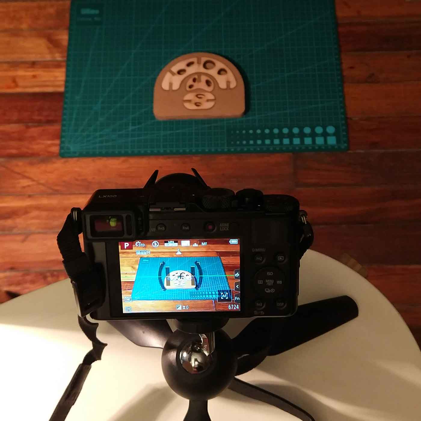
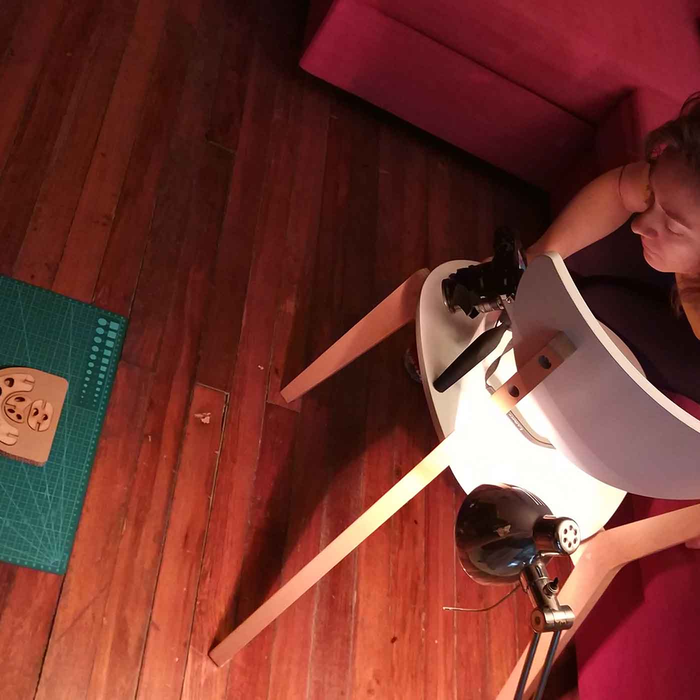
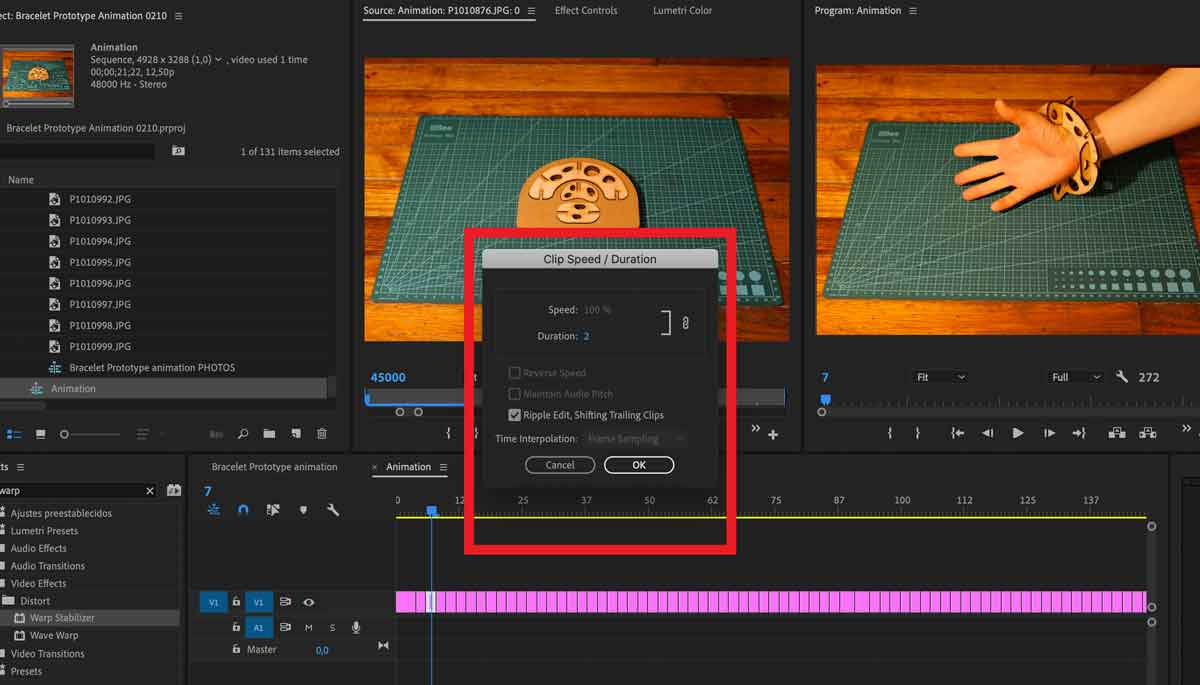
2_The camera we used has a stop-motion function, so after you've taken all the frames (127 in my case) the camera will render the video for you, but the speed of the frames was too fast so I had to adapt that using Adobe Premiere Pro.
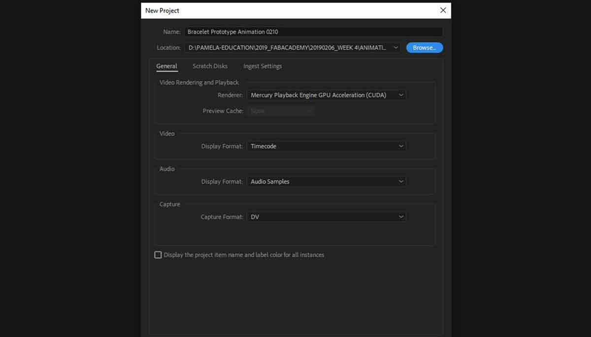
3_Create a new document on Premiere Pro, you can use this settings:
4_Drag all your photos in MEDIA, after that select the frame you want to modify the speed (clip speed).
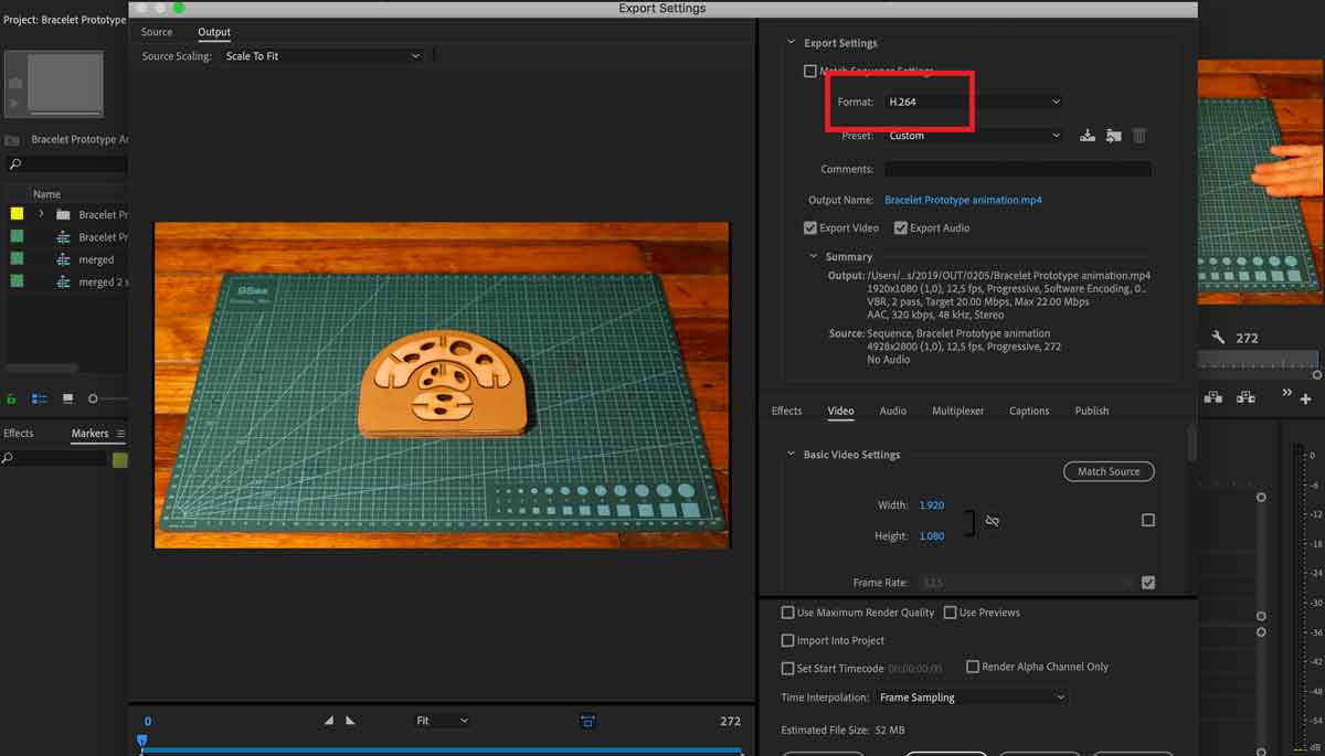
5_Export mode, if the video is going to be embedded as on this website you can go for HD settings as the ones I used:
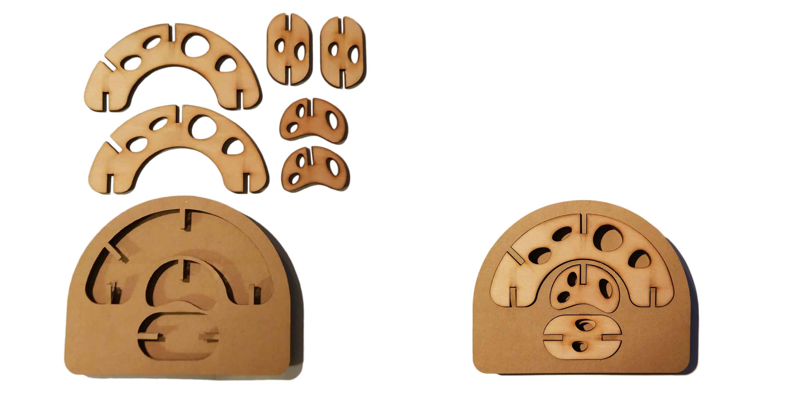
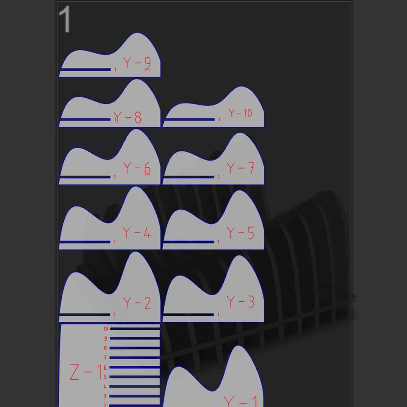
_Using SLICER
I was very curious about the software SLICER from AutoDesk and I decided to give it a try for
the first time.
SLICER is a free software (if you already have Fusion you can install it as a plug-in) that
allows you to literally slice a 3D model to then easily convert the document in a 2D pattern
that you can laser cut.
It has a simple and clear interface and you can get a quick idea of how to slice a model in a
few minutes.
I thought of doing a second prototype to document the process on how to use
SLICER and the outcomes I had.
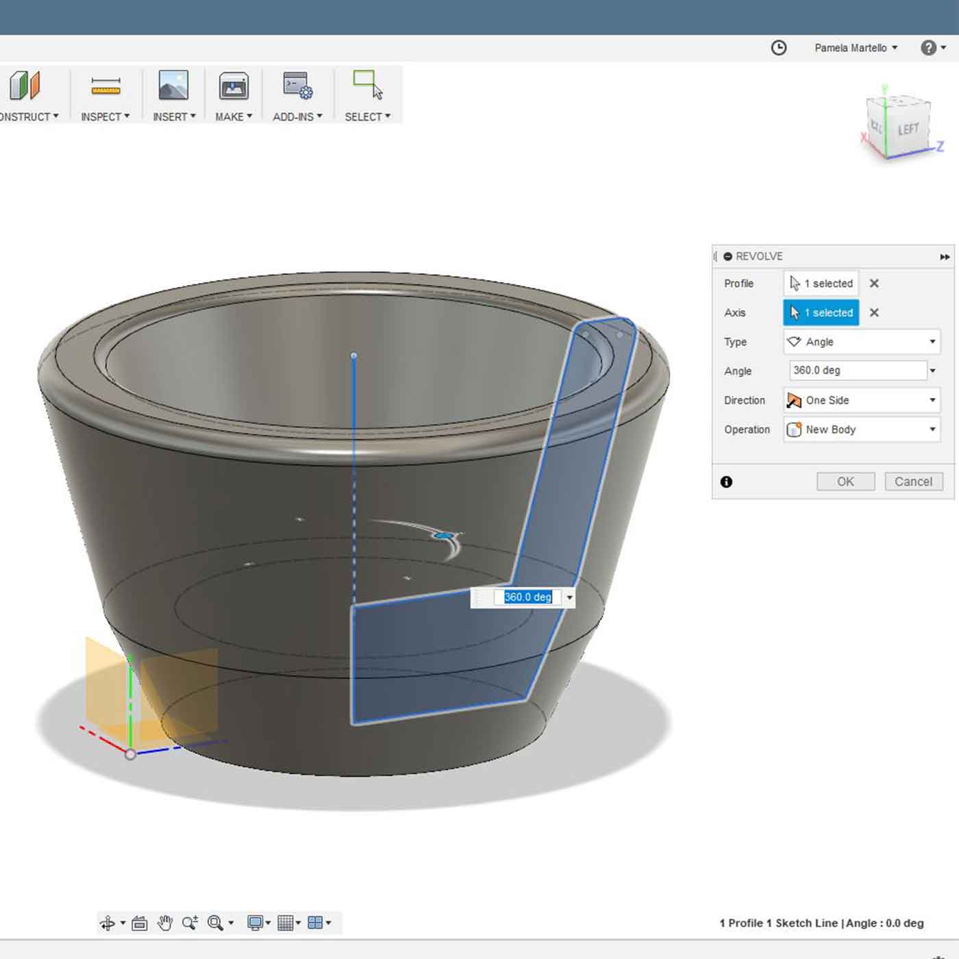
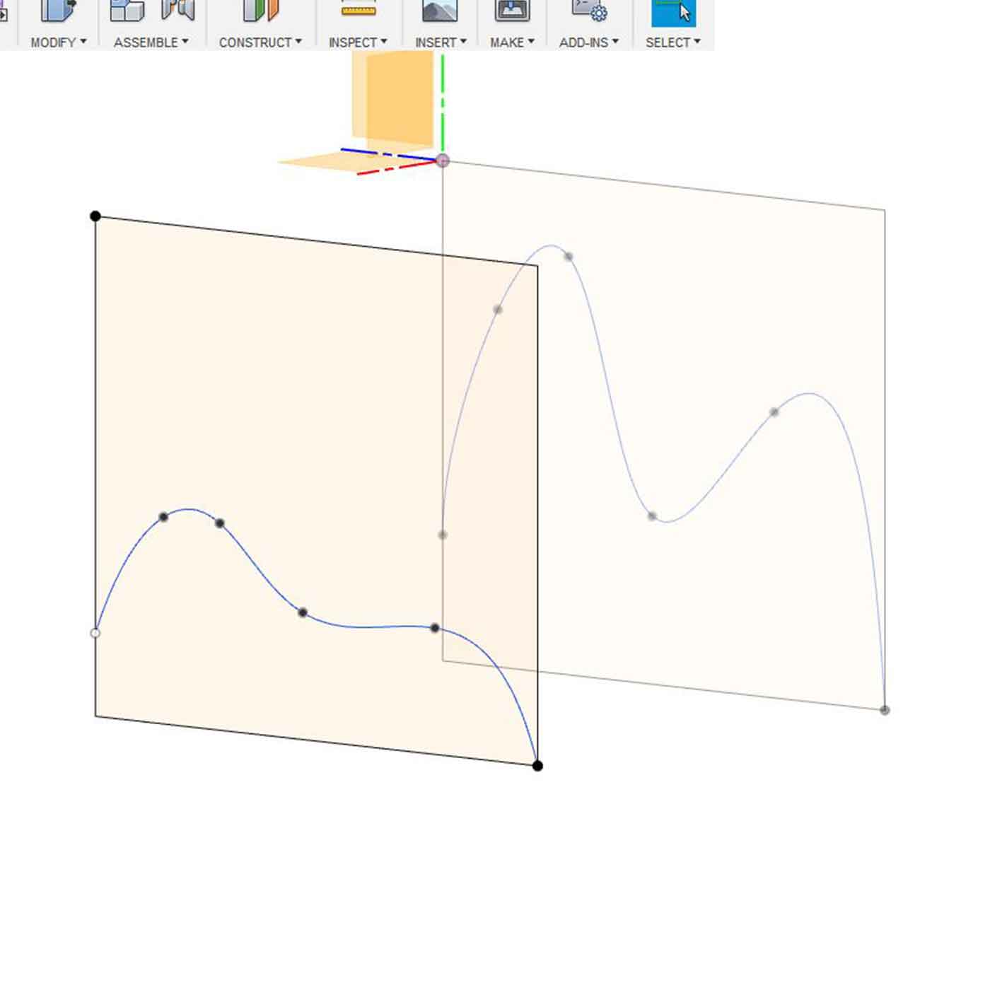
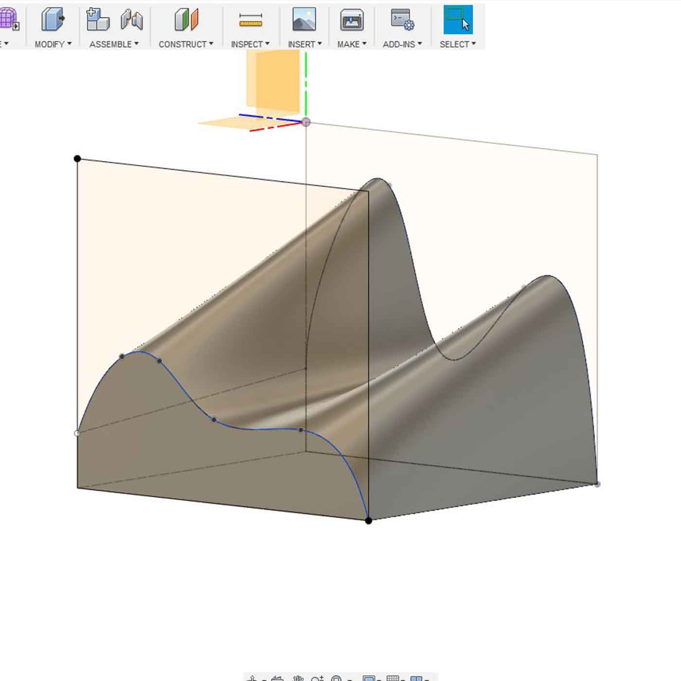
First you must design a 3D model, I discovered that the best geometries to use in slicer are those created from a REVOLVE or LOFT structure.
Here are a few models I tried out in slicer. Note that the red areas in the sliced render are error areas, I need to figure out why such a simple shape can generate that many errors in slicer.

Here is a short tutorial I made where I show you how to use SLICER after doing your 3D model in Fusion360:
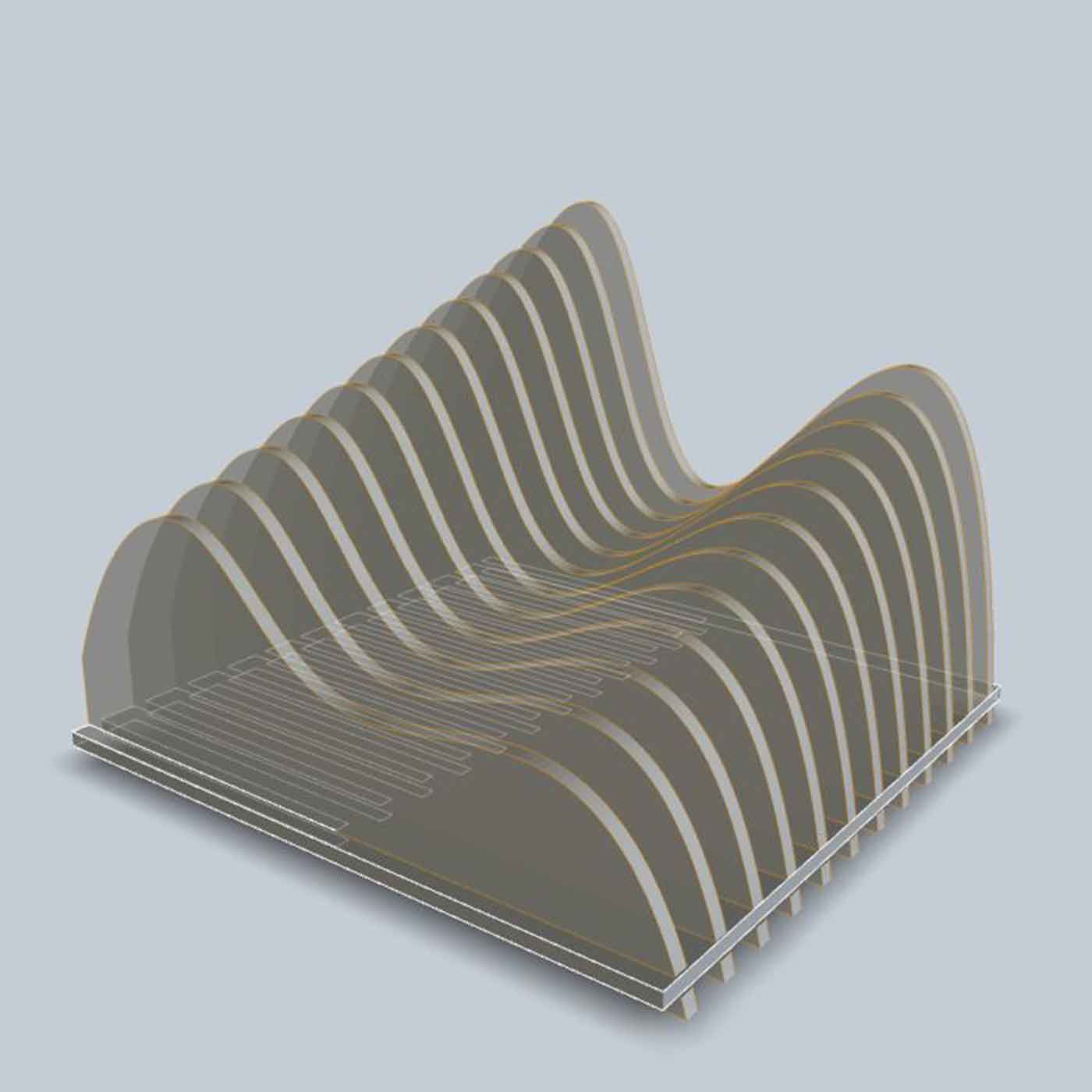
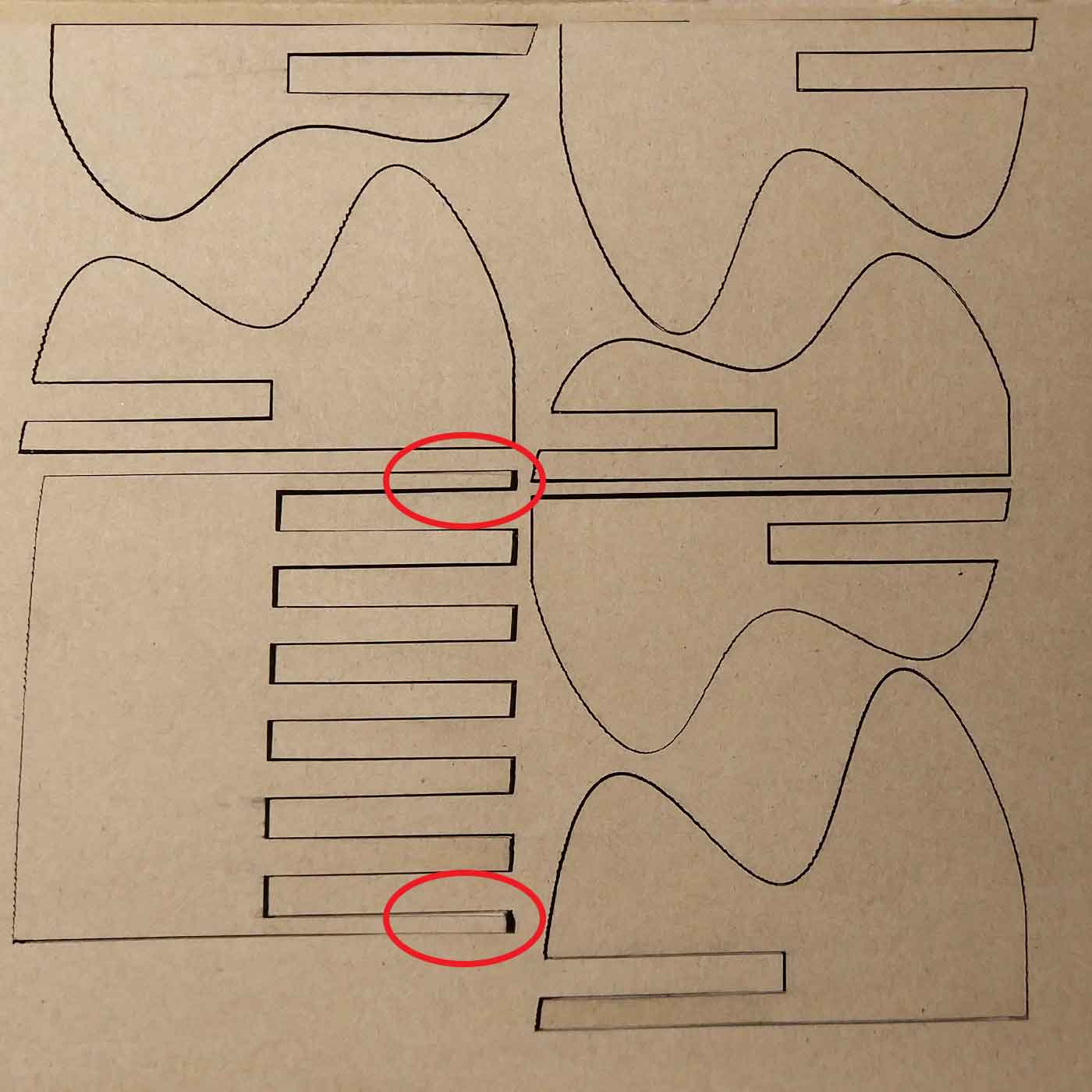
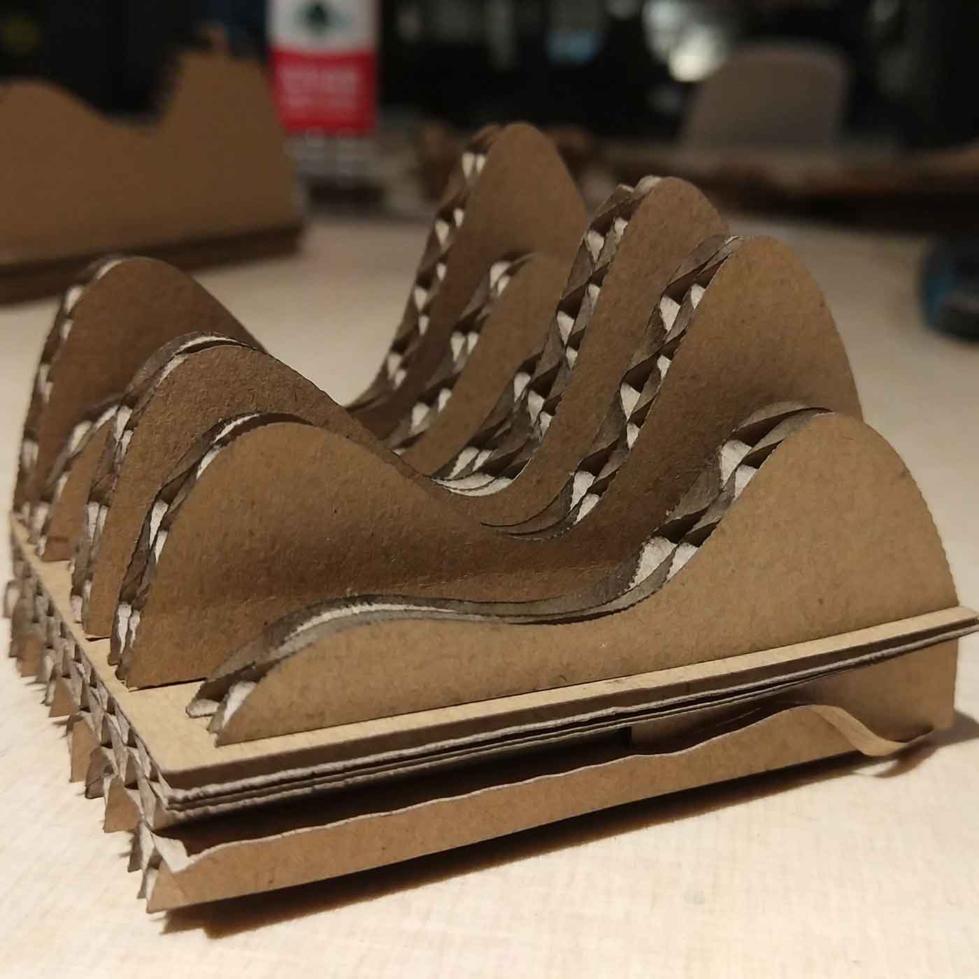
_SLICER outcome
I tested the mountains model I generated in Slicer.
The most evident issue is the horizontal layer (the base) the ends that were generated automatically
are too thin, this could be fixed afterwards with a vector software, but I would like to find out
how to improve the settings in SLICER to avoid a second work.
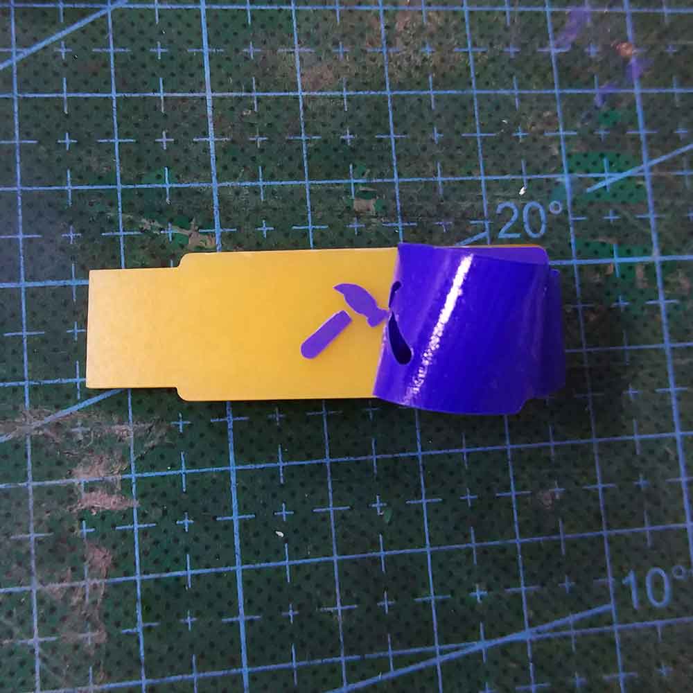
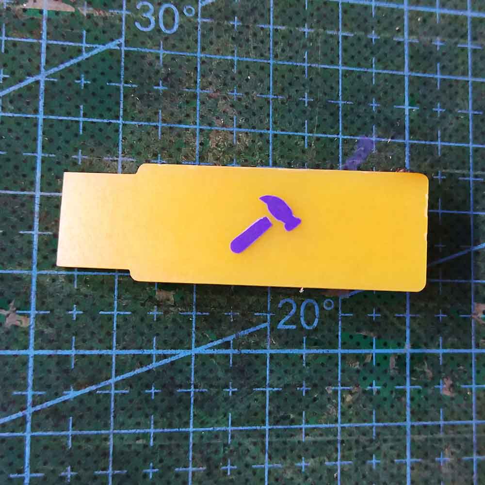
VINYL CUT
_PERSONALIZING MY FABISP
During this week's assignment we couldn't use the vinyl cutter as it was under maintenance. So during the next assignment (week5_electronics production) I decided to use the vinyl cutter to personalize my FABISP doing a sticker for the back side of it.
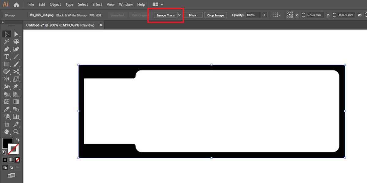
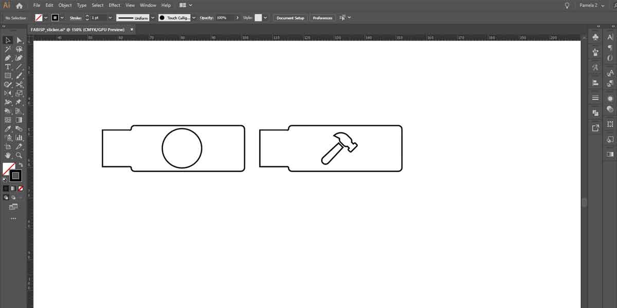
I did the 2D drawing using Adobe Ilustrator.
Firstly I opened inside Ai the PNG file of the FABISP outlines. I used "image trace" to retrace the
outlines and use it as my USB frame:
Then I drew some vectors the ones to cut in the vinyl. The idea was to cut 2 layers so that my USB
could gain some thickness and this could help when attaching it to the USB port.
Each layer is designed to be done in a different color.
I then saved my files as .EPS to import them into Roland Cut studio software.
But I had this error warning:
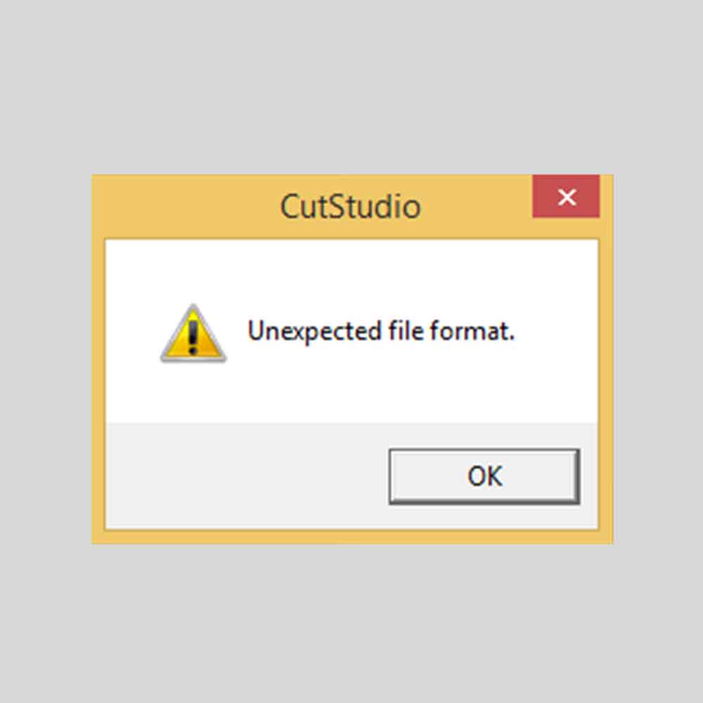
I tried several extensions and versions, and nothing worked.
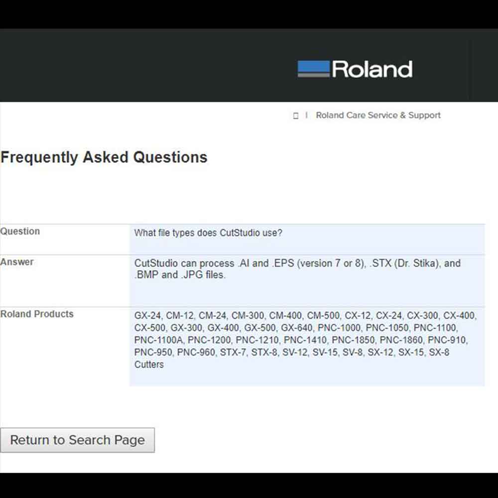
I went to Roland Cut studio to check the extensions supported, and I tried all of them but none
worked:
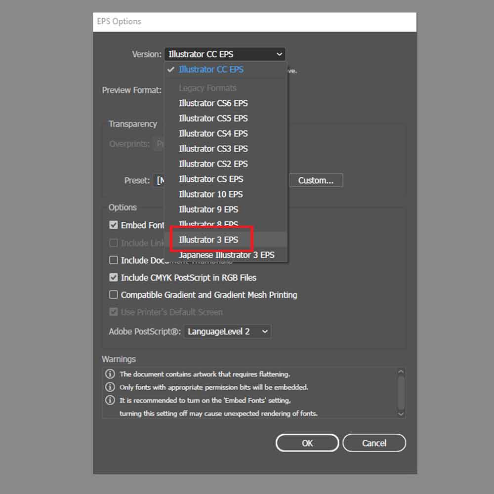
I then asked my classmates and one of them told me he saved as .EPS version 3 of Illustrator, and it turned out this version extension can be imported into our Roland Cut Studio program:
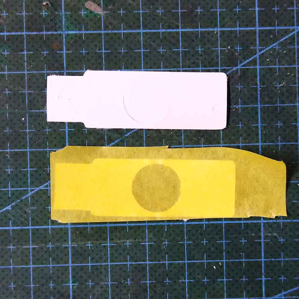
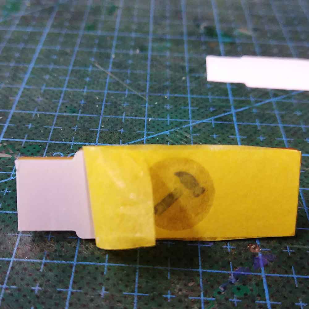
After this drawback I set up the machine and started doing some tests.
Some important settings you need to check are:
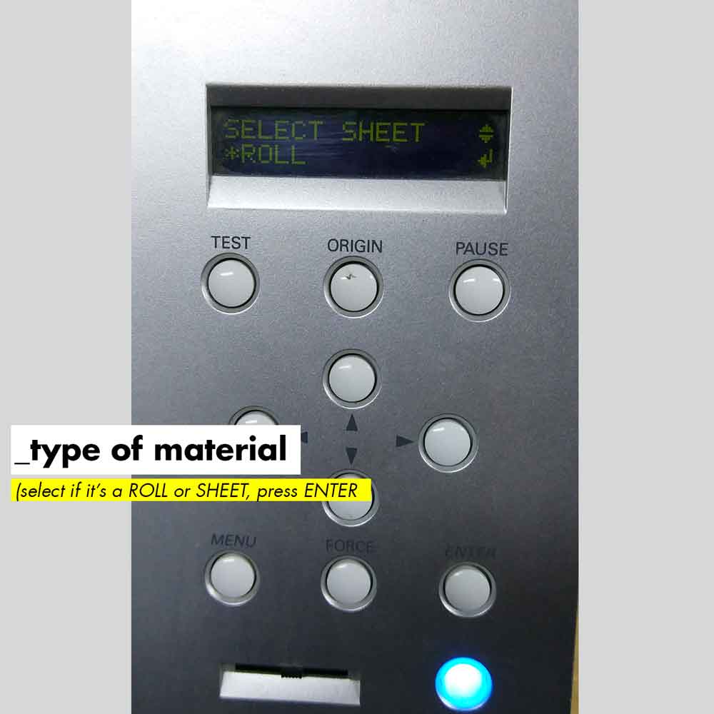
1_After you load the material, you have to select if it is a ROLL or a SHEET.
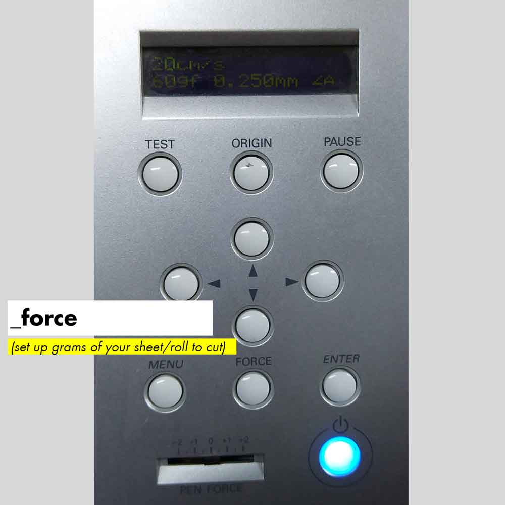
2_Select the force value. This will depend on the material sheet grammage.
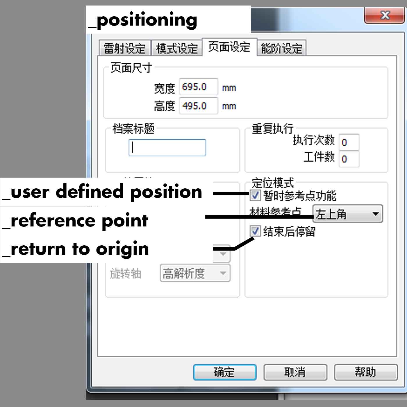
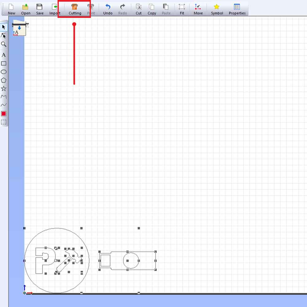
3_The position where you locate the vectors will affect where the machine will cut, so the preview
you see on the artboard of the software is actually the place where the machine will cut it.
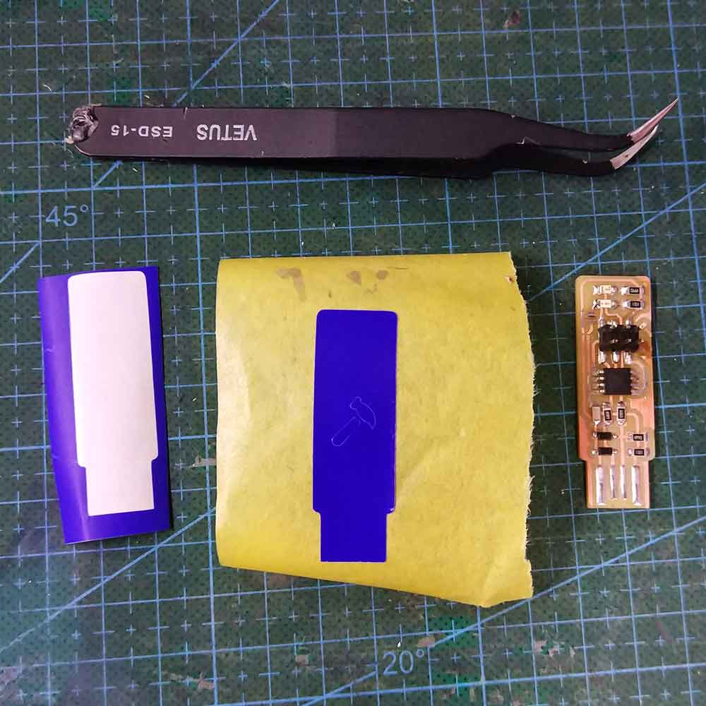
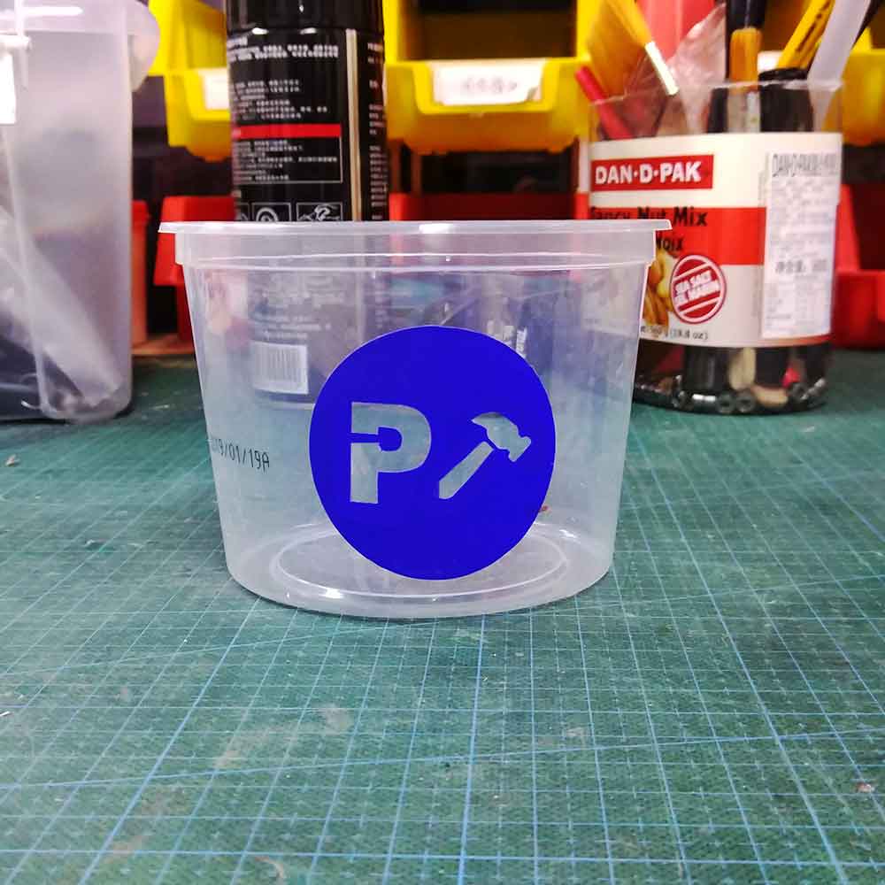
I ran a few tests and here are some of the outcomes. I even personalized a plastic box where I left my FABSIP at the lab.
_Improvements
The joints of the bracelet could be improved by adding an angle on the joints corner for a better fitting when assembling it.
_DOWNLOAD FILES
Here you can find the files I did on Fusion 360 for the bracelet and the mountains, plus the Illustrator files ready for laser cutting for both files as well:
_bracelet
laser cut kit
_bracelet
packaging
_bracelet fusion360 model
_mountains
fusion360 model
_vinyl
stickers for FABISP