_week 12
Output devices
Group assignment
This week we are still working with sensors, this time output devices.
And for the group assignment we have to "measure the power consumption of an output device."
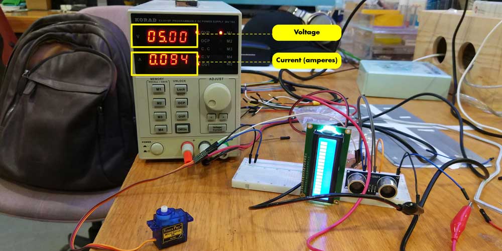
To measure the power consumption we can use the voltimeter and check the VOLTAGE "V" and the CURRENT "A" of the device or use a power supply as we did above and set the voltage to the used voltage, in our case is 5V and then set the current to 1 ampere, once you connect the devices and supply the voltage to it you will see the A value fluctuate, you can calculate the power consumption of your device using the electric power formula:
This would mean that the power consumption of the LCD screen was:
P=5*.094 -> P=0.47
Individual assignment
Neil mentioned that the learning curve of programing and electronics was steep, but my reality seems to be more like this:
yeap... it's been two complex weeks for me, it hasn't been easy, I've encountered a problem with my two
new boards that I can't find the issue (maybe the solution is in front of my eyes but I can't seem to
find it), and secondly I am having difficulties when using sensors and when it comes to program them
=(
I am trying hard and I hope I get more practice and experience and I can look back to this days and
laugh a bit...hopefully
Anyways, this week is about OUTPUT DEVICES and what is an output device?
The communication between an information processing system, such as a computer, and the outside world, possibly a human or another information processing system. Inputs are the signals or data received by the system and outputs are the signals or data sent from it. *source wikipedia
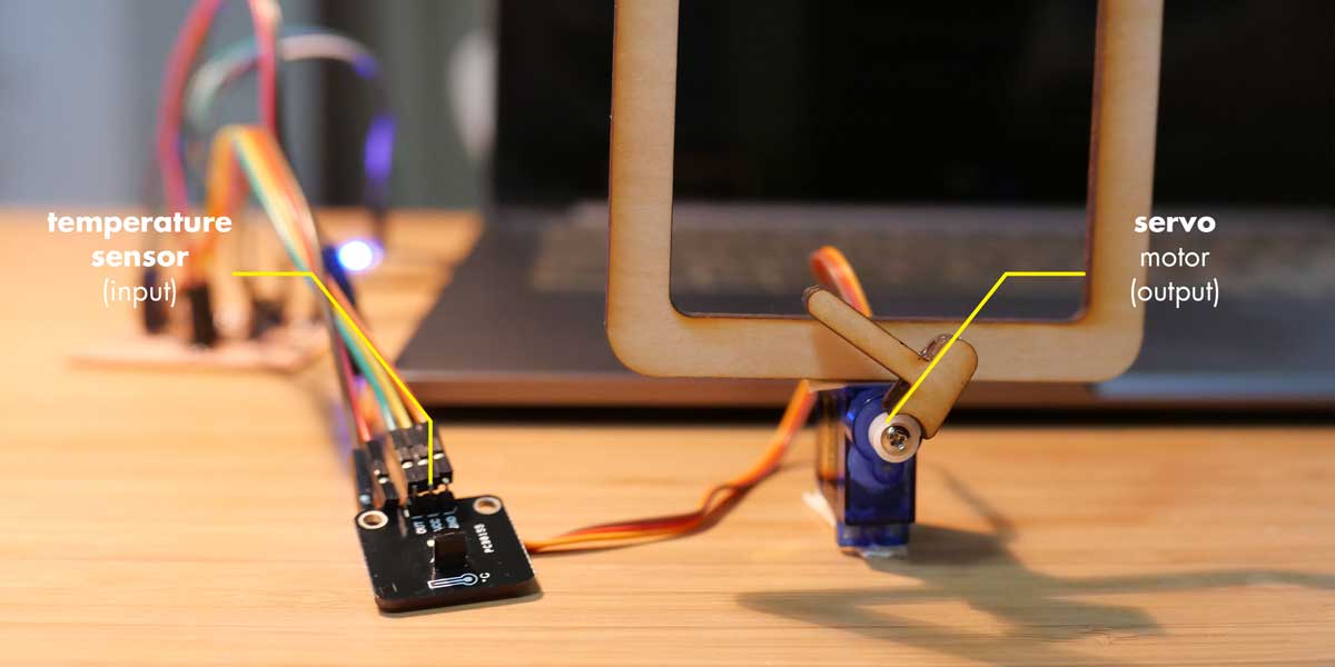
So the data we are receiving from a device is an output, and during this week I wanted to use output devices that would help me with my final project, mainly a servo motor (as an output), a temperature sensor and/or a rain sensor(as input devices). But during the process of doing this assignments I tried to use as well an LCD display sensor
As last week my board had an issue with the FTDI connection I decided to modify some things of my previous sarduino board and make a new one, hoping I could solve the issue.
_SARDUINO 2.0
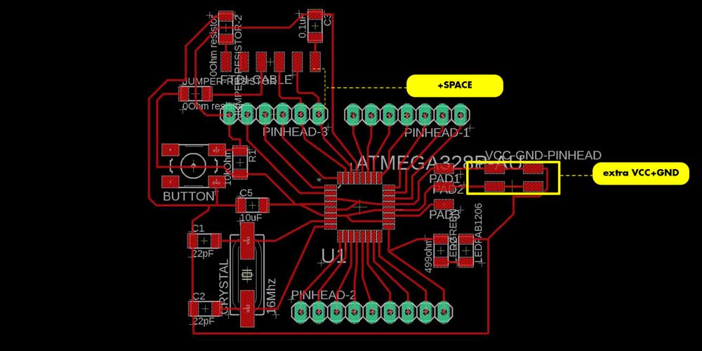
First thing I did was to check inside my Eagle file all the connections of the board to make sure I did
the correct wiring on the traces.
After that I decided to add extra VCC and GND, this way if I needed to connect more than
one sensor I wouldn't use a breadboard as an extra component for the wiring (if those sensors use low
current).
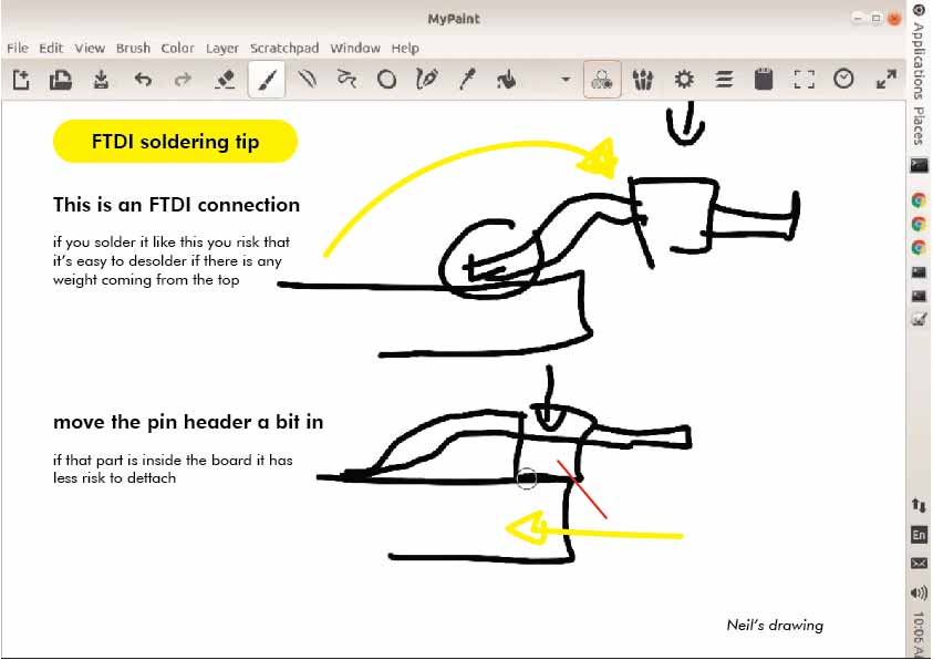
Then as the space between my FTDI pin headers and the other pin headers was a bit too close for
soldering, I decided to move the FTDI a bit up to have more space and make the soldering easier.
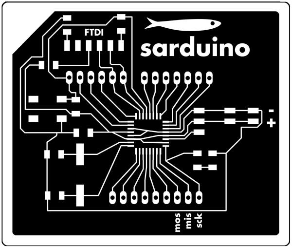
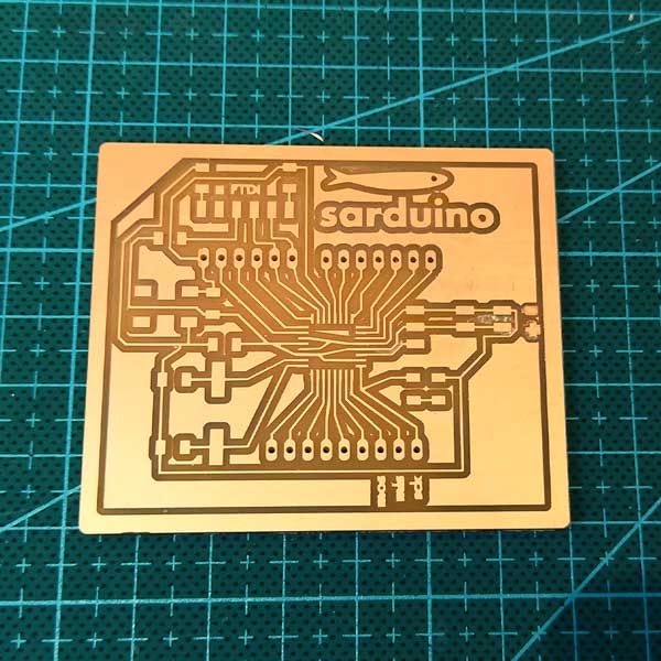
Here is how the new board looked like:
I added as well some icons to MISO, MOSI, SCK, VCC, GND and FTDI group so I could have a quick access to these pins.
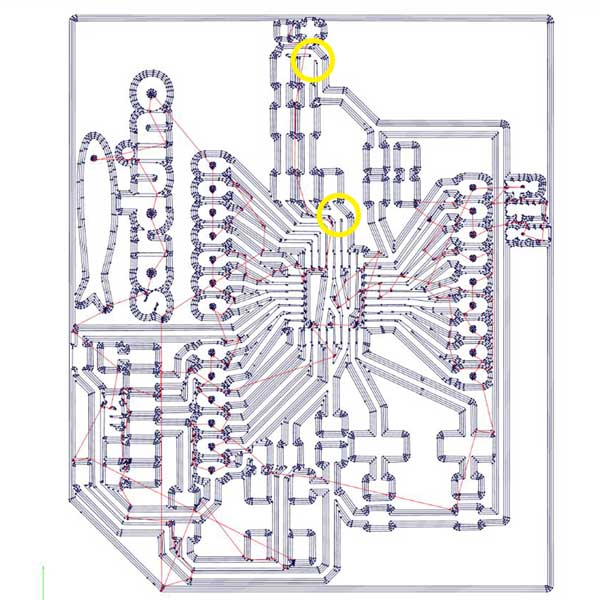
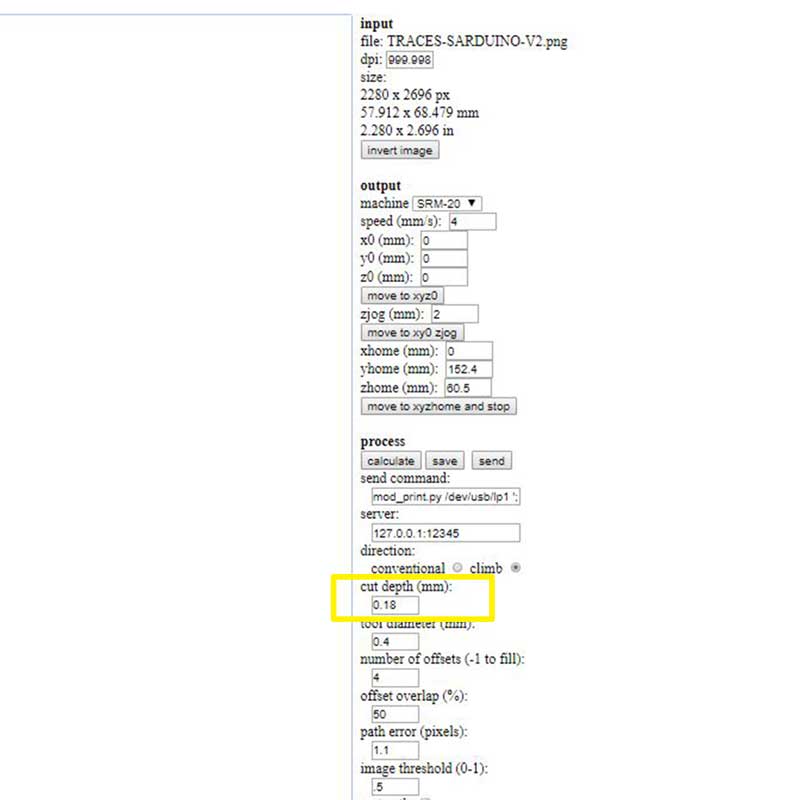
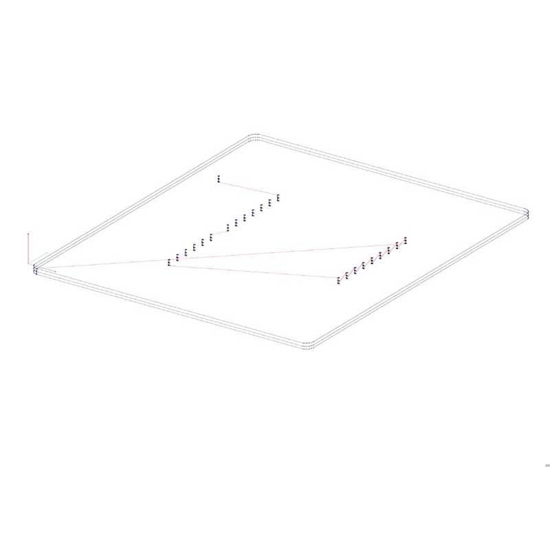
Next time I do a new board I could leave a bit more space in between the traces (or use as it's recommended the FAB DRC). When I finished the milling two the traces were attached and I had to cut by hand those small attachments, which where very tiny but if I didn't see them this could have created a short.
I used 0.18mm for the cut depth.
_TIPS & ADVICES
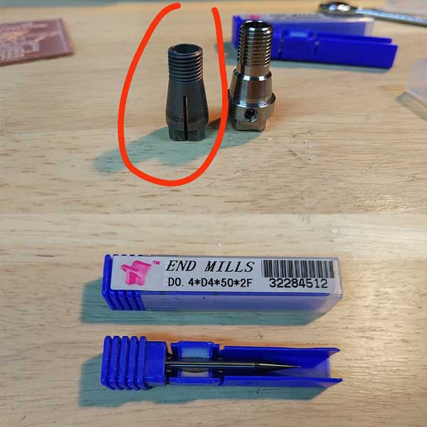
When doing the milling, the first board I did the endmill left very rough traces and most of them broke, and I found out another endmill worked much better, here is the photo of the endmill I should use next time (in our lab), and the type of collet it uses. This collet has no hole so it is a bit tricky when doing the Z axis zeroing, you have to place the endmill inside the collet don't tight all the way, zero the axis after that move up the Z axis and that's when you can tighten the collet.
Here is a comparison photo of the results I had with two different endmills.
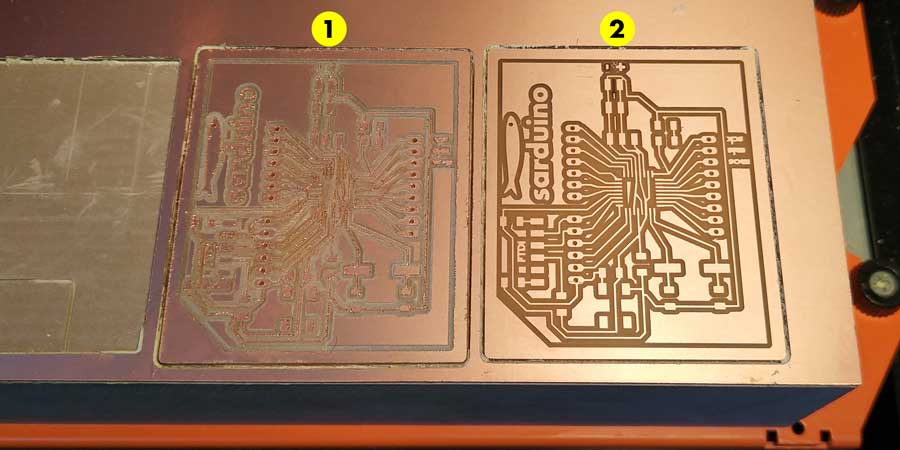
To get the results from number 2 make sure you use the endmill and collet from the photo below:
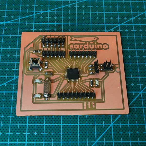
As I thought my last board the soldering could have been the error issue, after the milling process I carefully soldered all the components, making sure there was enough soldering and waiting the right time when using the soldering iron.
_PROGRAMMING MY BOARD
When trying to program my board, I first connected the FABISP to check if it worked and it all seemed to
be ok, I then connected the FTDI cable, and... same problem as last week, the FTDI connection is not
working.
I tried to switch RX,TX, use a different FTDI cable, connect the FTDI in a different order, checked the
continuity of the components with the voltimeter, checked the soldering, cleaned the board with alcohol,
connected CTS to GND, but nothing happened.
Same error as last week and I can't figure out what is the issue, I am still working on it but I've ran
off ideas of what could be the issue.
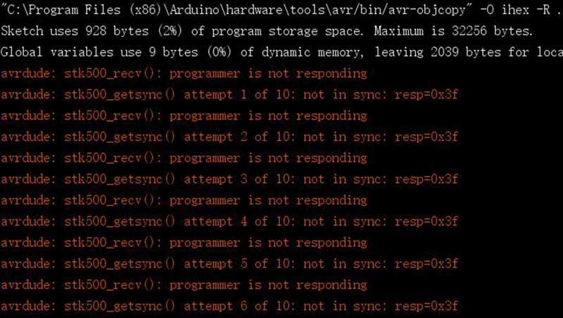
When connecting my board through the FTDI cable to upload the arduino code, this is the error message I get:
stk500_getsync() / stk500_recv()... programmer is not responding
I haven't been able to solve the issue, but in the meantime while I try to understand where could be the error, I tried some programming using output devices.
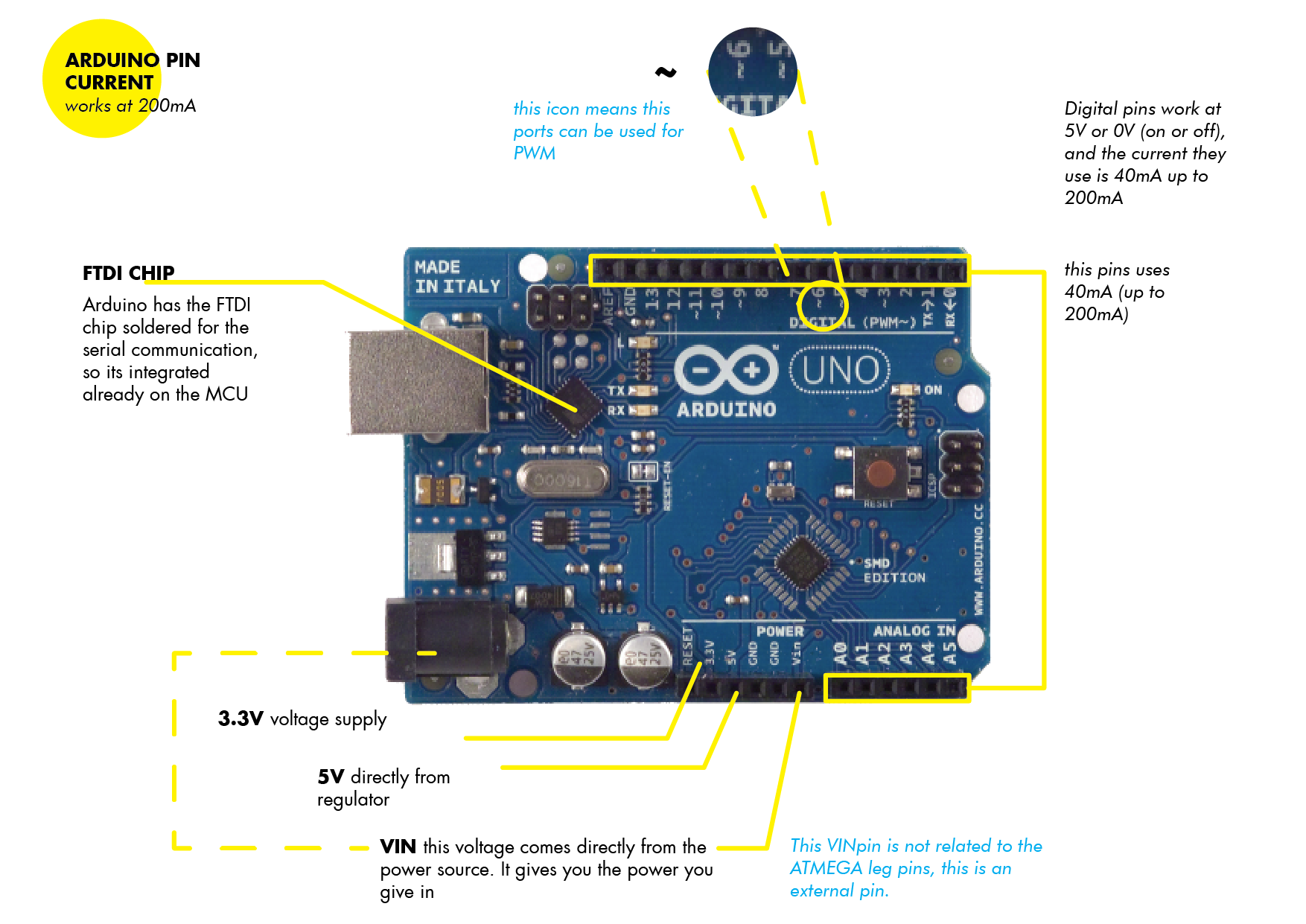
As the board I am using takes reference from the Satshakit and it's an Arduino compatible board, it is useful to understand the pin out and meaning of some pins on the real Arduino Genuino Uno. Some of the Arduino example codes I will be using this week use the pin Arduino pin out, so is useful to note the following:
_SERVO MOTOR
What is a servo motor?
A servomotor is a rotary actuator or linear actuator that allows for precise control of angular or
linear position.
(source wikipedia)
The servo motor I will be using, a tiny but powerful micro servo 9g SG90, allows you to control the movement of a tiny motor that can rotate 180 degrees. You can attach things and also combine it's usage with other sensors.
During this week I want to use the servo motor and control the movement with an input sensor (rain drop
sensor or temperature sensor).
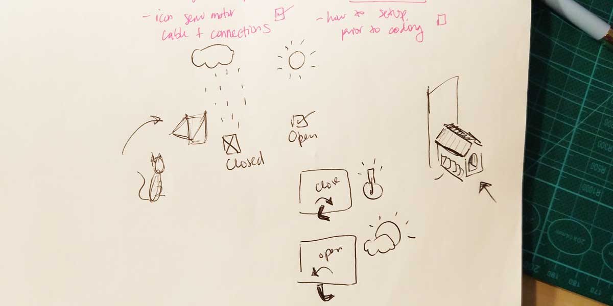
The idea of using this sensonr on my project is that this servo would have attached a hook (or similar)
that will lock or unlock my cat's door entrance. And I wanted to add a feature to the door so that when
it is raining, the door stays locked so my cat can't go out. This is why I wanted to use the servo
together with another input device.
It is important to remember when using a servo motor how the wiring works.
You should connect orange to signal, red to VCC and brown to gnd.
Mapping temperature with servo motor rotation angle
This is the code I did for making the servo motor to move according to temperature changes:
/* Sweep
by BARRAGAN
by Scott Fitzgerald http://www.arduino.cc/en/Tutorial/Sweep */ #include
int sensorPin=A0;
int temp=0;
int randomTemp=0;
int sensorValue=0;
Servo myservo; // create servo object to control a servo
// twelve servo objects can be created on most boards
int pos = 0; // variable to store the servo position
int tempMap=0; // variable to store the temperature 0 degrees in this case
void setup() { //fixed variables
myservo.attach(9); // attaches the servo on pin 9 to the servo object
}
void loop() {
// read the temperature //we did this as a debugging
// randomTemp=random(0,45);
// Serial.println(randomTemp);
readSensor();
// map temp to srvo angle
tempMap=map(temp,10,35,0,180);
// write temperature to servo
pos=tempMap;
myservo.write(pos);
delay(1000);
// if (randomTemp < 18){ // pos=180; // myservo.write(pos); // tell servo to go to position
in
variable 'pos' // delay(15); // waits 15ms for the servo to reach the position // waits 15ms
for
the servo to reach the position // } else { // pos=90; // myservo.write(pos); // tell servo
to
go to position in variable 'pos' // delay(15); // } } void readSensor(){ //this is a way
of
cleaning the code, simplifying it sensorValue=analogRead(sensorPin); temp=(5.0 * sensorValue
*
100.0) / 1024; }
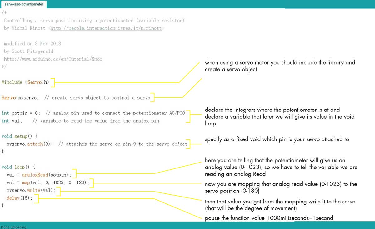
I also tried the basic knob code provided in the Arduino basic examples. It uses a servo motor and a potentiometer.
The potentiometer is an analog input what it does when turned is to change the amount of resistance, which you can use to control other sensors like in this case to control the degree of movement of a servo motor.
And to use a potentiometer together with a servo motor you need to map the values of each device, meaning as the potentiometer is an analog device its values ranges from 0 to 1023 and the servo motor movement angle goes from 0 to 180 degrees. This means you need to use the mapping function to use both variables together servo position+potentiometer position.
This is a very simple formula but I breaked it down to better understand the logic behind it:
Here's a video of the knob code, I wanted to use some props to make the movement have a purpose, and I imaged this as a locking scenario for my cat's entrance door.
You can find the knob code inside Arduino examples or on this link knob example, or here:
/*
Controlling a servo position using a potentiometer (variable resistor)
by Michal Rinott
Fitzgerald http://www.arduino.cc/en/Tutorial/Knob */ #include
Servo myservo; // create servo object to control a servo
int potpin = 0; // analog pin used to connect the potentiometer A0/PC0
int val; // variable to read the value from the analog pin
void setup() {
myservo.attach(9); // attaches the servo on pin 9 to the servo object
}
void loop() {
val = analogRead(potpin); // reads the value of the potentiometer (value between 0 and 1023)
val = map(val, 0, 1023, 0, 180); // scale it to use it with the servo (value between 0 and
180)
myservo.write(val); // sets the servo position according to the scaled value
delay(15); // waits for the servo to get there
}
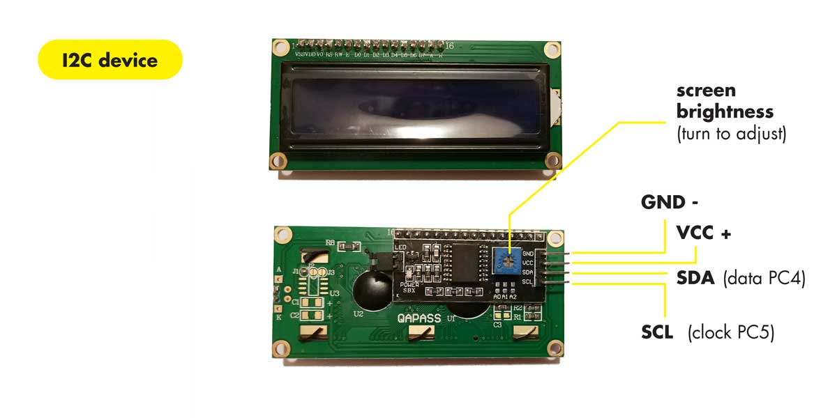
_LCD DISPLAY
An LCD means Liquid Crystal Display and it is a display screen.
The oneI will be using is a 16x2 display, which means that it can display 16 characters in
2 lines (16 each line).
Before you start programming an LCD display on Arduino you need to do the following:
1_Find a LiquidCrystal code for a basic Hello World! display
example 1 example 2
2_Know the address of the device, as we are using a I2C LCD display you can run a
"scan" code on arduino to find out what is the device address which you will be needing
for your code. Just copy the code provided on this link into arduino and then open the serial
monitor, you will get a value, in my case the LCD display I was using showed I2C device found at
address 0x27!
3_Once you ran the scan change on your code the LCD address, if you are using the same "hello world"
example I provided above remember to include the Wire.h and
LiquidCrystal_I2C.h libraries.
4_Data sheet LCD I2C display link
This is a schematic of the wiring if you are using an LCD I2C:
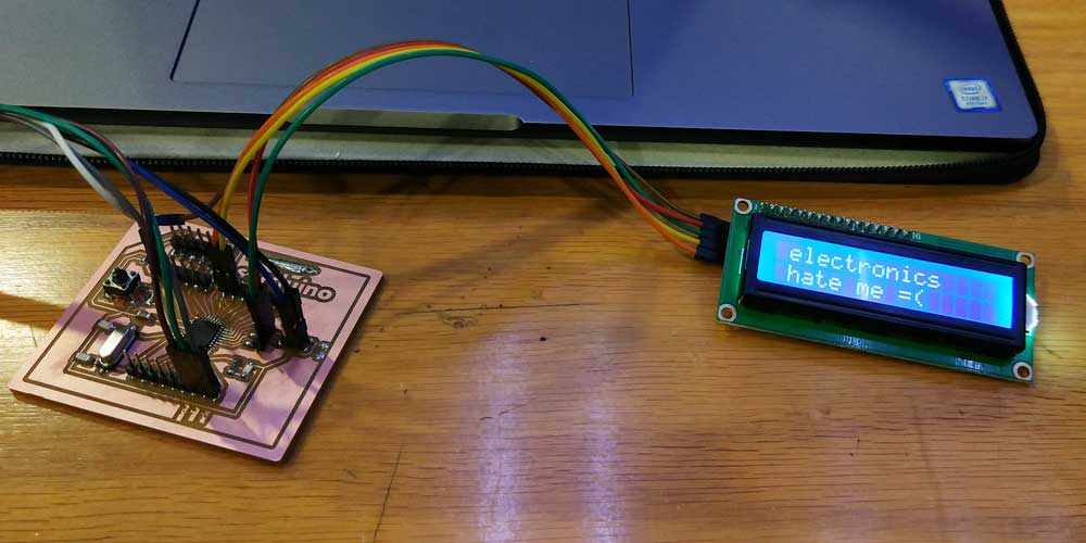
During my first attempt using the LCD I2C device I had some issues, when uploading the
"Hello
World!"
code, I was getting no message on the screen, so I thought it was the screen contrast
regulation, but when i moved the contraste still nothing appeared.
It took me a while to figure out the issue, and it was that in our lab we have two identical I2C screens
and I thought both used the same address 0x27,16,2, but in fact each of them uses a
different address the other uses 0x3F,16,2, i figured it out after running the scan
function once again.
After that I ran the code and it worked!
This is the code for the simple Hello world display:
#include
#include
LiquidCrystal_I2C lcd(0x3F,16,2); // set the LCD address to 0X3F or 0x27(depends on the
model)
for a 16 chars and 2 line display
void setup()
{
lcd.init();// initialize the lcd
lcd.init();
// Print a message to the LCD.
lcd.backlight();
lcd.setCursor(1,0);
lcd.print("electronics");
lcd.setCursor(1,1);
lcd.print("hate me =(");
}
void loop()
{
}
After this first baby step I decided to look for other codes less static, and I found a cool pacman animation for the LCD screen.
Here you can find the original code written by
Massimo Musante
.
I used his code and added some text to it, here's the test:
Here is the code ad did some modifications besides the basic setup for the LCD address:
#include
#include
LiquidCrystal_I2C lcd(0x3F,16,2); // set the LCD address to 0x3F or 0x27(Cooperate with 3 short
circuit caps) for a 16 chars and 2 line display
int backlightState = LOW;
long previousMillis = 0;
long interval = 1000;
// make some custom characters:
byte pac1Def[8] = { //this bites generate a smiley face, you can play with the values and see
what comes out
B00000,
B01110,
B11011,
B11111,
B11111,
B01110,
B00000,
B00000
};
byte pac2Def[8] = {
B00000,
B01110,
B10100,
B11000,
B11100,
B01110,
B00000,
B00000
};
byte pillDef[8] = {
B00000,
B00000,
B00000,
B01100,
B01100,
B00000,
B00000,
B00000
};
const byte pac1 = 0x0;
const byte pac2 = 0x1;
const byte pill = 0x2;
const int del = 250;
int x = 0;
int y = 0;
int px = 0;
int py = 0;
void setup() {
lcd.init(); // initialize the lcd
lcd.backlight();
lcd.home();
// create a new character
lcd.createChar(0, pac1Def);
// create a new character
lcd.createChar(1, pac2Def);
// create a new character
lcd.createChar(2, pillDef);
// set up the lcd's number of columns and rows:
lcd.begin(16, 2);
lcd.setCursor(1,0);
lcd.print("electronics");
lcd.setCursor(1,1);
lcd.print("hate me =(");
}
void loop() {
anim();
x++;
if(x>15 && y == 0)
{
x = 0;
y = 1;
}
else if(x>15 && y == 1)
{
x = 0;
y = 0;
fill();
}
}
// Initial display fill
void fill()
{
lcd.setCursor(0,0);
lcd.write(0); //pac1
for(int j=0;j<7;j++)
{
lcd.print(" ");
lcd.write(2); //pill
}
lcd.setCursor(0,1);
lcd.write(2); //pill
for(int j=0;j<7;j++)
{
lcd.print(" ");
lcd.write(2); //pill
}
}
// character animation
void anim()
{
lcd.setCursor(px,py);
lcd.print(" ");
lcd.setCursor(x,y);
lcd.write(1); //pac2
delay(del);
lcd.setCursor(x,y);
lcd.write(0); //pac1
delay(del);
px = x;
py = y;
}
Here is a good tutorial I found on how to create graphics on your LCD display. I still want to try a bit
more of codes for this.
LCD DISPLAY TUTORIAL
createChar() I found a few more interesting codes to play with the LCD, you can create some simple animations on a LCD display. This animations are limited by the pixels on the screen, normally the characters supported are 5x8 pixels.
autoscroll() is an interesting function for LCD in Arduino IDE, it moves the text/symbols
left to right.
You can find basic examples inside arduino library. I modified the code on this website for the autoscroll example, and
then I used and modified the HelloWorld_i2c example provided on the NewliquidCrystal_1.3.4.zip to create the
simple animation. And to create the smiley I used the arduino example inside createChar references.
I also found a cool custom character generator that generates symbols and its Arduino code. You can check it out here and play a bit to generate some symbols auto generator.
Here is the video of the exercises using the LCD display:
This is the code I used for the animations of the dots:
#include
#include
#define BACKLIGHT_PIN 13
LiquidCrystal_I2C lcd(0x27,16,2); // Set the LCD I2C address
//LiquidCrystal_I2C lcd(0x27,16,2, BACKLIGHT_PIN, POSITIVE); // Set the LCD I2C address
char * message = "hello maker!";
// Creat a set of new characters
const uint8_t charBitmap[][8] = {
{ 0xc, 0x12, 0x12, 0xc, 0, 0, 0, 0 },
{ 0x6, 0x9, 0x9, 0x6, 0, 0, 0, 0 },
{ 0x0, 0x6, 0x9, 0x9, 0x6, 0, 0, 0x0 },
{ 0x0, 0xc, 0x12, 0x12, 0xc, 0, 0, 0x0 },
{ 0x0, 0x0, 0xc, 0x12, 0x12, 0xc, 0, 0x0 },
{ 0x0, 0x0, 0x6, 0x9, 0x9, 0x6, 0, 0x0 },
{ 0x0, 0x0, 0x0, 0x6, 0x9, 0x9, 0x6, 0x0 },
{ 0x0, 0x0, 0x0, 0xc, 0x12, 0x12, 0xc, 0x0 }
};
void setup()
{
lcd.init(); // initialize the lcd
lcd.setCursor(3,0);
lcd.backlight();
int charBitmapSize = (sizeof(charBitmap ) / sizeof (charBitmap[0]));
// Switch on the backlight
pinMode ( BACKLIGHT_PIN, OUTPUT );
digitalWrite ( BACKLIGHT_PIN, HIGH );
for ( int i = 0; i < charBitmapSize; i++ ) { lcd.createChar ( i, (uint8_t *)charBitmap[i] );
}
lcd.home (); // go home lcd.print("testing graphics ");
lcd.setCursor ( 0, 1 ); // go to the next line
lcd.print (" groovy ");
delay ( 2000 );
}
void loop()
{
for (int printStart = 15; printStart >= 0; printStart--) //scroll on from right
{
showLetters(printStart, 0);
}
for (int letter = 1; letter <= strlen(message); letter++) //scroll off to left
{
showLetters(0, letter);
}
}
void showLetters(int printStart, int startLetter)
{
lcd.setCursor(printStart,1);
for (int currentLetter = startLetter; currentLetter < strlen(message);
currentLetter++)
{
lcd.print(message[currentLetter]);
}
lcd.print(" ");
delay(250);
lcd.home ();
// Do a little animation by writing to the same location
for ( int i = 0; i < 2; i++ )
{
for ( int j = 0; j < 16; j++ )
{
lcd.print (char(random(7)));
}
lcd.setCursor ( 0, 1 );
}
delay (200);
}
This is the code for the smiley scroll:
#include
LiquidCrystal_I2C lcd(0x27,16,2);
char * message = "hello maker!";
byte smiley[8] = { //I changed some numbers to make a bit different the smiley =)
B10000,
B10001,
B00000,
B00000,
B10001,
B01110,
B00000,
};
void setup()
{
lcd.init(); // initialize the lcd
lcd.setCursor(3,0);
lcd.backlight();
lcd.createChar(0, smiley);
lcd.begin(16, 2);
lcd.write(byte(0));
}
void loop()
{
for (int printStart = 15; printStart >= 0; printStart--) //scroll on from right
{
showLetters(printStart, 0);
}
for (int letter = 1; letter <= strlen(message); letter++) //scroll off to left { showLetters(0,
letter); } } void showLetters(int printStart, int startLetter) {
lcd.setCursor(printStart,1);
for (int currentLetter=startLetter; currentLetter < strlen(message); currentLetter++) {
lcd.print(message[currentLetter]); } lcd.print(" ");
delay(250);
}
This is the code for the autoscroll that generates some arrows pattern:
/*
LiquidCrystal Library - Autoscroll
Demonstrates the use a 16x2 LCD display. The LiquidCrystal
library works with all LCD displays that are compatible with the
Hitachi HD44780 driver. There are many of them out there, and you
can usually tell them by the 16-pin interface.
This sketch demonstrates the use of the autoscroll()
and noAutoscroll() functions to make new text scroll or not.
The circuit:
LCD RS pin to digital pin 12
LCD Enable pin to digital pin 11
LCD D4 pin to digital pin 5
LCD D5 pin to digital pin 4
LCD D6 pin to digital pin 3
LCD D7 pin to digital pin 2
LCD R/W pin to ground
10K resistor:
ends to +5V and ground
wiper to LCD VO pin (pin 3)
Library originally added 18 Apr 2008
by David A. Mellis
library modified 5 Jul 2009
by Limor Fried (http://www.ladyada.net)
example added 9 Jul 2009
by Tom Igoe
modified 22 Nov 2010
by Tom Igoe
This example code is in the public domain.
http://www.arduino.cc/en/Tutorial/LiquidCrystalAutoscroll
*/
// include the library code:
#include
// initialize the library with the numbers of the interface pins
LiquidCrystal_I2C lcd(0x27, 16, 2);
void setup() {
// set up the LCD's number of columns and rows:
lcd.init(); // initialize the lcd
lcd.setCursor(3, 0);
lcd.backlight();
}
void loop() {
lcd.setCursor(15, 0); // set the cursor to column 15, line 0
for (int positionCounter1 = 0; positionCounter1 < 18; positionCounter1++) {
lcd.scrollDisplayLeft(); //Scrolls the contents of the display one space to the left.
lcd.print("<-- -->"); // Print a message to the LCD these are some sort of arrows that create
a
pattern when scrolling
delay(500); //wait for 250 microseconds
}
lcd.clear(); //Clears the LCD screen and positions the cursor in the upper-left corner.
}
This is a personal note, I would like to check out more information about the RTC CLOCK ARDUINO so that I could possibly use it as the input sensor to time the closure of the door:
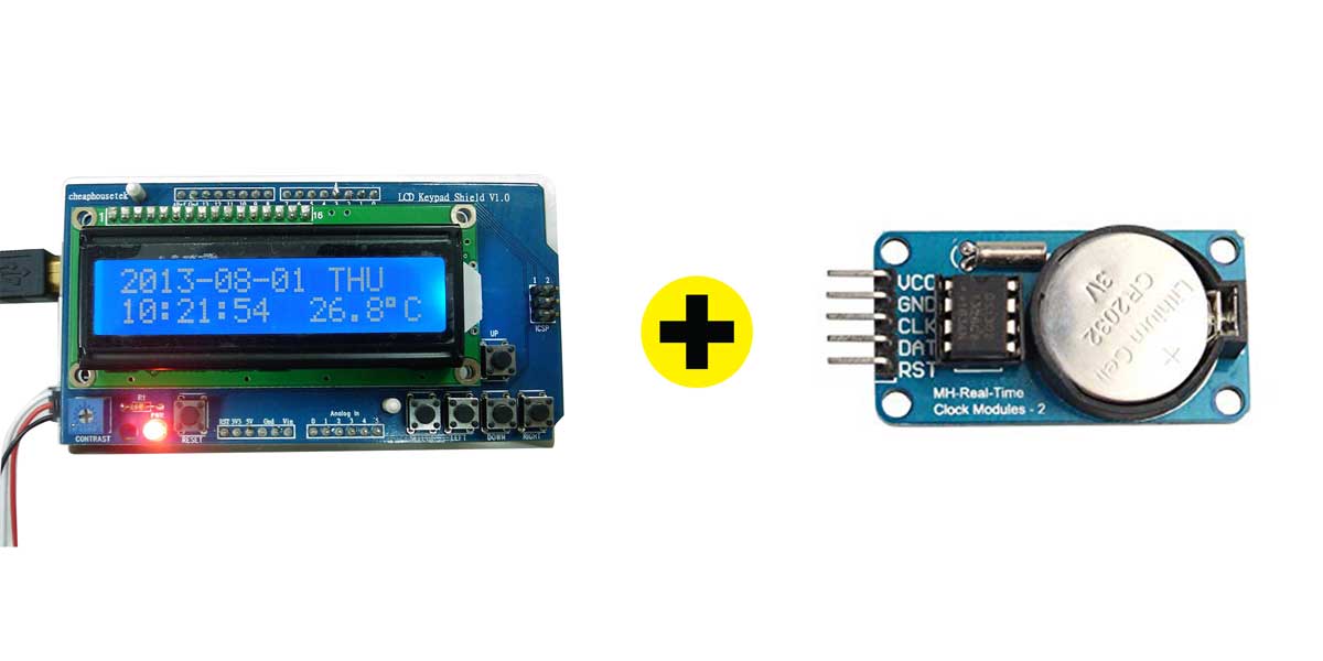
photos from internet, source: rtc clock, lcd temp display,
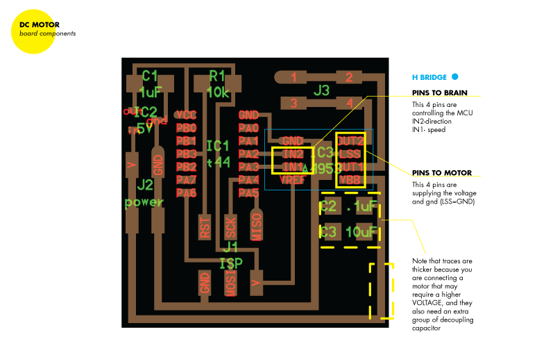
_OUTPUT DEVICES BOARDS NOTES
I would like to add some extra notes about this week's schedule material.
From the boards examples Neil provided this week, there are a few of them that caught my attention. And I
would like to try using them and apply them into the creation of a jewelry line that uses these and
other sensors:
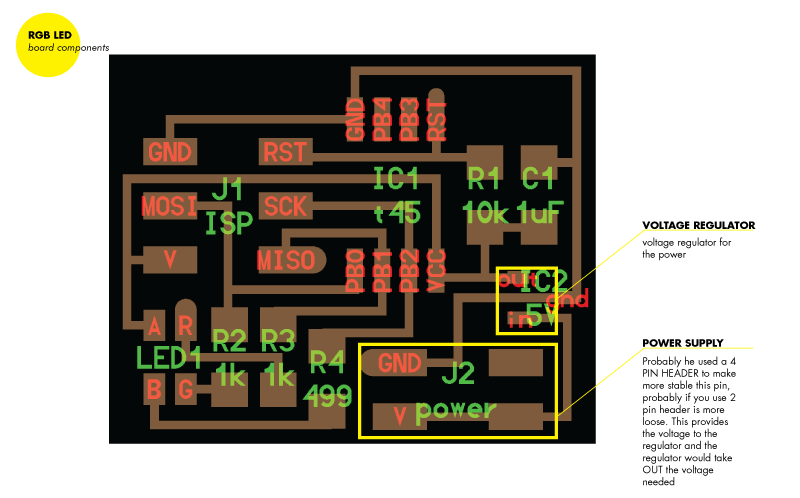
1_RGB LED
2_the super cool LED array
3_video
On the examples of these boards, some of them have some new (for me) interesting components/solutions that I would like to integrate on future boards:
_USEFUL RESOURCES
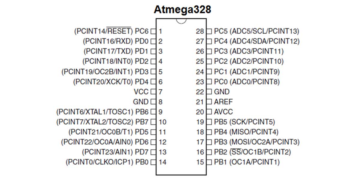
Throughout this and last week I used a lot the following pin outs for the ATMEGA328, so I leave here the links and images that will be useful and are handy to have during these two weeks:
1_ATmega328 DATA SHEET
2_ATmega328 TOP VIEW
3_ATmega328 pin out
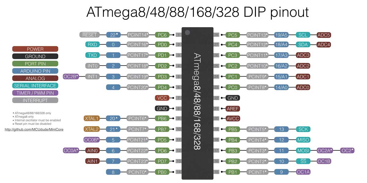
4_ARDUINO GENUINO UNO FUNDAMENTALS
_FTDI or other pin headers soldering TIP:
_CODES DOWNLOADS
_hello world
_hello
pacman
_servo
motor + temperature sensor
_autoscroll+symbols
_smiley+autoscroll
_animation
_SARDUINO
SCHEMATIC
_SARDUINO
BOARD