Electronics production
Week 05
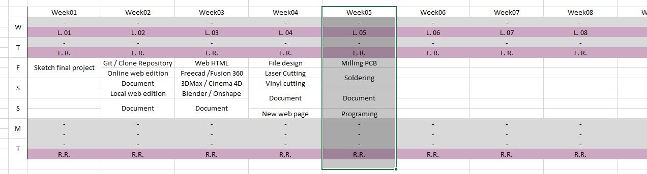
Like every week I started the week planning the assignment.
Group assignment. Characterizing the machines
I am a remote student and none of my colleagues are in the fab academy, so I did this part of the assigment individualy.
These are the machines, materials and settings that I used for this assignment:
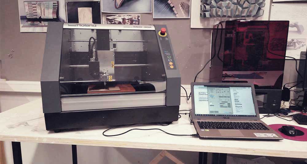
Mini CNC Milling Machine: Roland MDX-40A
- Software: Fab Modules + VPanel
- Settings: detailed in the section “Milling a PCB”
- Tools: milling bit 0,4 mm (1/64”); milling bit 0,8 (1/32”)
- Material: FR-1 Printed Circuit Board 101,6x127 mm. (5X4”)
Milling PCB
For this assignment I used the mini CNC Roland MDX-40A, which has a maximum working area of 300x300 mm. I used V-Ppanel to control the machine and Fab Modules to generate the .rml files.
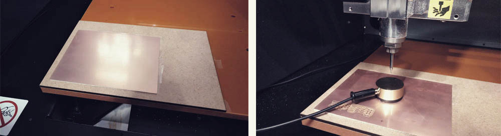
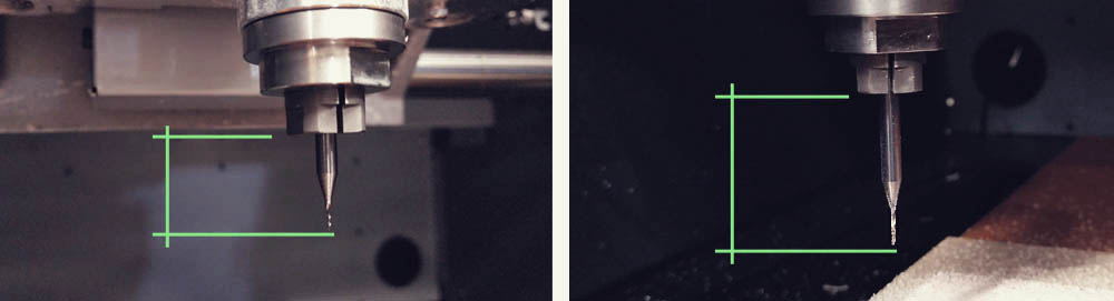
The first thing that I did was to replace the old base protector material for a new one. Then I used double side tape to fit the FR-1 board on it. Once this was done, I changed the milling bit and set my new x0, y0 and z0 using V-Panel.
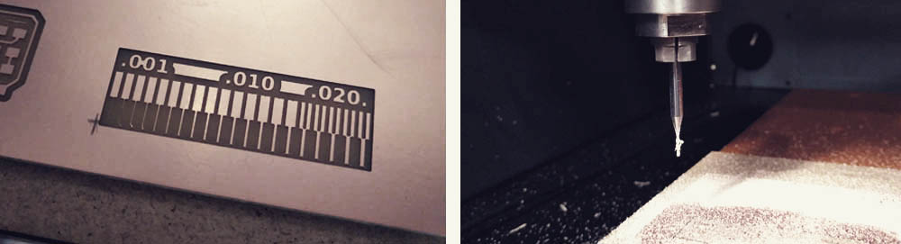
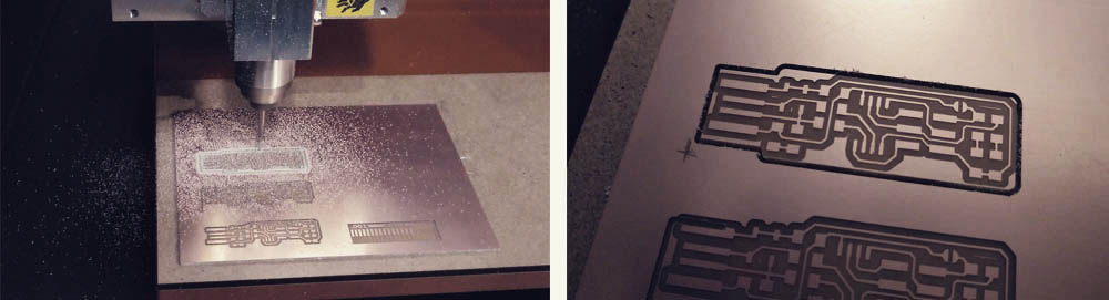
Then I milled some test files until to get a good result. Due to the double side tape, when the machine cuts all the way throw the outline of our pieces, it gets very dirty but it is easy to clean.
But be extremely careful!! The tip of these milling bits are so thin that is very easy to break them (I broke one just barely touching it with my hand when I was cleaning the machine work space with the vacuum)..
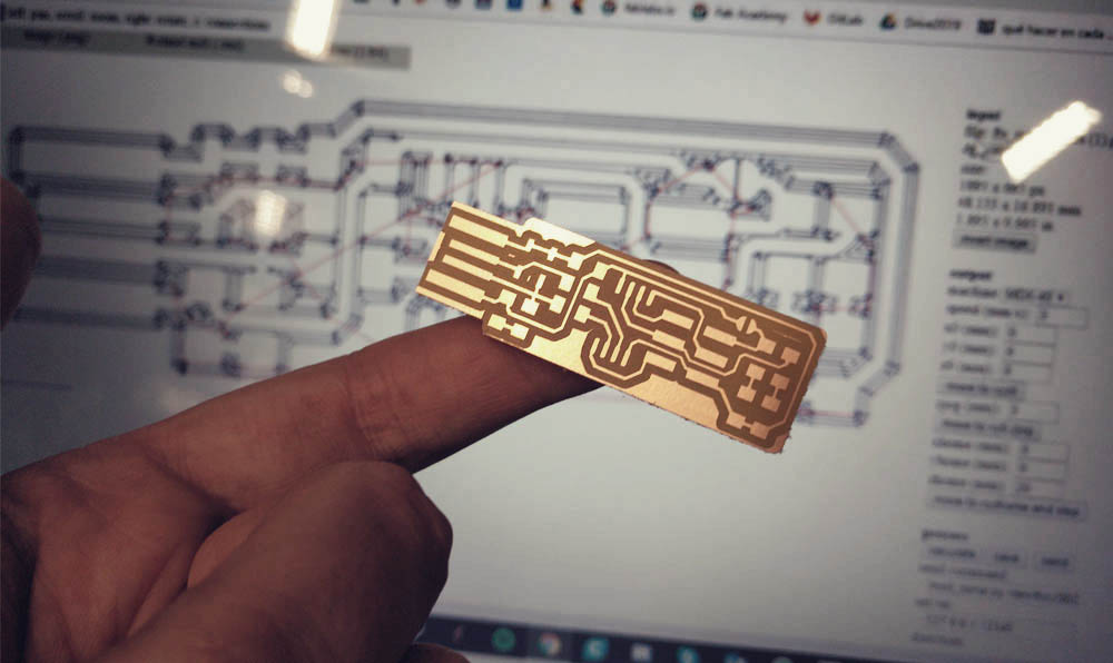
Creating .rml files in Fab Modules
I decided to use the “Brian PCB Design” so I downloaded the .pngs files. Then I imported them in Fab Modules, I configured the different options and saved the file.
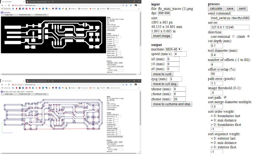
After several unsuccessful trials I found out two things:
1.- The x0, y0 and z0 is the origin. If you set 0,0,0 here, the machine will take as the origin the origin that you set in V-Panel. You can modify this numbers if you want, but I do not recommend you to change de z, otherwise is probably that you break the milling bit or damage the material or the machine. Keep it always in cero.
2.- The xhome, yhome and zhome is where the machine goes when it finish the job. If you want that the machine comes back to the initial 0,0,0, set here 0,0,0. But if you do that probably you will damage your material and your milling bit because the bit will skim while is returning to the 0,0,0. So, independent of you want to change the xhome and yhome, you always need to give some positive number to the xhome to avoid to touch the surface of the material.
Sending files from V-Panel to MDX-40A
In V-Panel I loaded the .rml that a got from Fab Modules and I sent it to the machine. I was working with 14.000rpm for the rotation speed.
I sent some files without problems and suddenly this error showed up: The MDX-40A is paused. Command Error (RML-1).
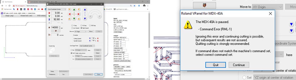
This didn’t make any sense to me. I didn’t pause the machine anytime… I tried to fix it from many different ways: I clicked “quit”, I clicked “continue”; I closed the error window from the x on the upper right corner. I did it like 20 times but nothing worked. I turned off the machine and the computer a few times. I even reinstalled the drivers and software and I also tried with other computer but nothing, nothing worked. And when I tried to send the file clicking “continue” the machine started moving up and down without any logic… I was stuck with this problem like four hours. But then a former Fab Academy student, Jose Real, told me that he had a similar problem once and he fixed it by moving out a bit the milling bit from the collet. So I did it and voila!! No errors.
The issue was that the distance between the tip of the milling bit and the surface of the material, what means the z distance, was quite large and for some reason is was producing an error when V-Panel was reading the .rml file. (at the beginning I had like 105mm. and after I reduced to 92mm.). So there are two ways to solve it, or you move out the milling bit from the collet or you add a thicker base. The idea is the same: to reduce the z distance.
It was a relief to find the solution above all because either in the window error or the user manual doesn’t give you any key of what is referring to or how to solve it. Thank you so much for all the help Jose!
Finally I was able to cut my circuit boards.
Assembling electronic components
I had never soldered electronic components to a circuit board. I had no experience at all. So I started practicing on the pieces that went out bad.
I recommend you work in an illuminated area, whit a lot of room around you. This takes time, just relax and breathe. It is a very delicate work so try to find a separate space where you can be focused on the work. And have ready all the tools and components so you can use it as soon as you need them.
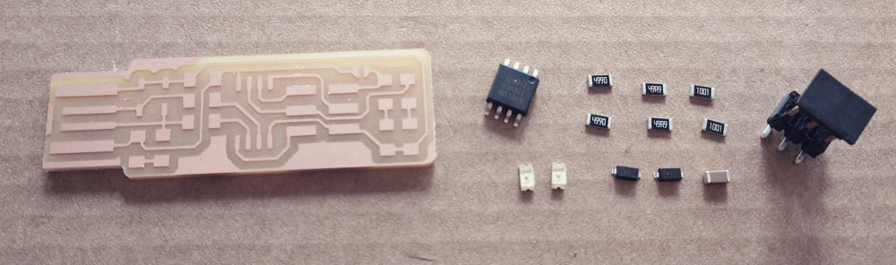
When I learned, more or less, the technique for melting tin and so on, I looked for the necessary components. The components that we need for the Brian fabISP are:
> 1 x ATtiny45 or ATtiny85 (U1)
> 2 x 1kΩ resistors (R1, R6)
> 2 x 499Ω resistors (R2, R5)
> 2 x 49Ω resistors (R3, R4)
> 2 x 3.3v zener diodes (D1, D2)
> 1 x red LED (D4)
> 1 x green LED (D3)
> 1 x 100nF capacitor (C1)
> 1 x 2x3 pin header (ISP)
From here on, I was following this diagram to know where each components should be placed..
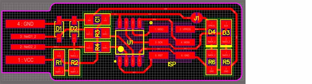
Please, note that some components must be installed in a specific orientation:
> The zener diodes are marked, both in the drawing and on the packages, with a line on the cathode side.
> The LED cathodes on the PCB drawing are marked with thicker lines. Package marking conventions differ between LED manufacturers, but there is usually a green or black line visible on the cathode side of the epoxy lens.
> The ATtiny45 marks pin 1 with a dot laser-etched into the corner of the package. Pin 1 is marked in the drawing with a dot as well.
You can placed the rest of the components in any orientation.
I messed-up a circuit board because I placed one of the LEDs with the incorrect orientation…
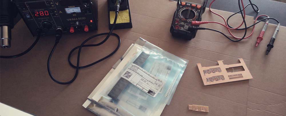
While I was installing the components I was checking with the multimeter that everything was ok.
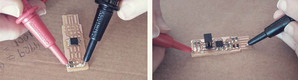
I was doing this all the time. Seriously, all the time. I set a component and I checked that I had continuity. That gave me confidence and allows me to check that the component was good soldered.
And this is the result:
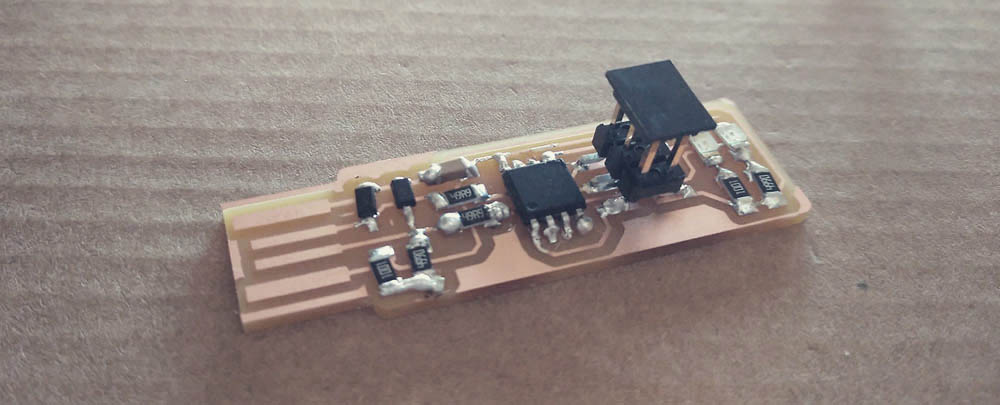
This assignment was quite difficult for me. I was so nervous because the components and the circuit board are so tiny that you can mess it up at any moment that my hands didn’t stop shaking so it was difficult to solder properly. Also at the beginning it was really hard for me to understand the diagrams and most of the time I was guided by the pictures instead of the diagrams.
The result is not my best work but considering that it was my first time I think is good. I will continue improving my technique in following assignments… By the way, I need to buy some tips for the solder (I burned two because I was using the solder station at full power…)
Programming
For this last step I continued following the Brian’s tutorial which is really great.
I can’t explain it better than he does, but I would like to add just a couple of comments refer to some problems that I had during the process:
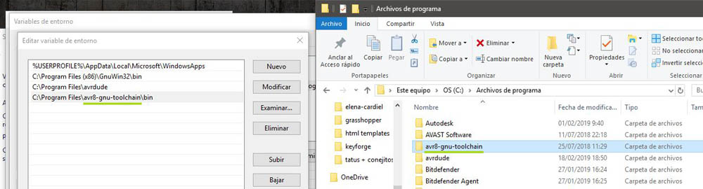
1.- Check that the name of your files in program files are the same that the ones that you have in the paths. In my case an error “command not found” showed up in Git Bash when I was checking the installation because I wasn’t using the same folder’s name.
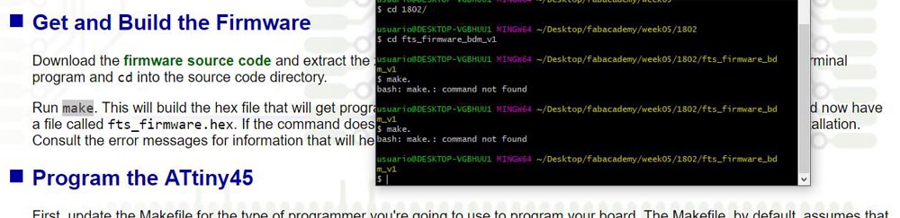
2.- When you see in the tutorial “run make” or “run make flash”, “run make rstdisbl” you have to type it in your terminal without the point at the end. Yes, don’t look at me with that face. When I was in the step “get and build the firmware”, The first 10 times I copied the command “make” with the point at the end and, as you can imagine, every time Git Bash sent me the message “command not found”.
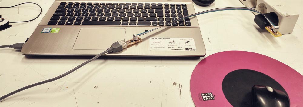
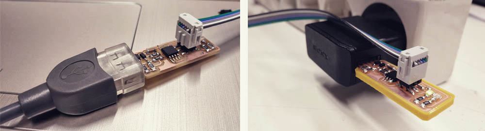
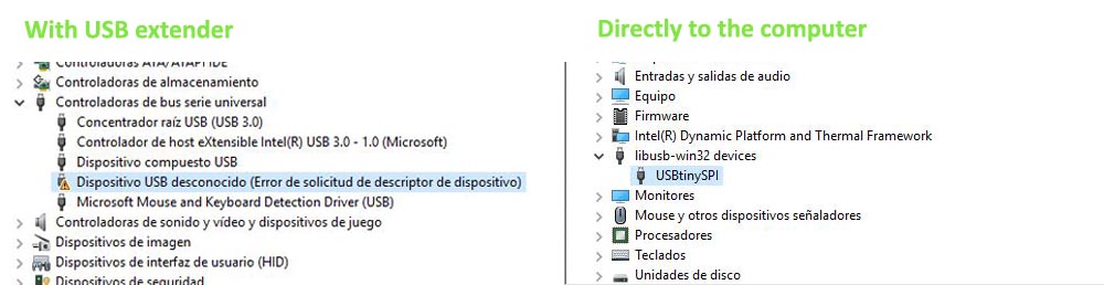
3.- When I was in the step “Test the USB functionality” the computer didn’t recognise my FabISP, the one that I had just programed. I had it connected to the computer by an usb extender. Then I connected it directly to the usb in the computer and it worked.
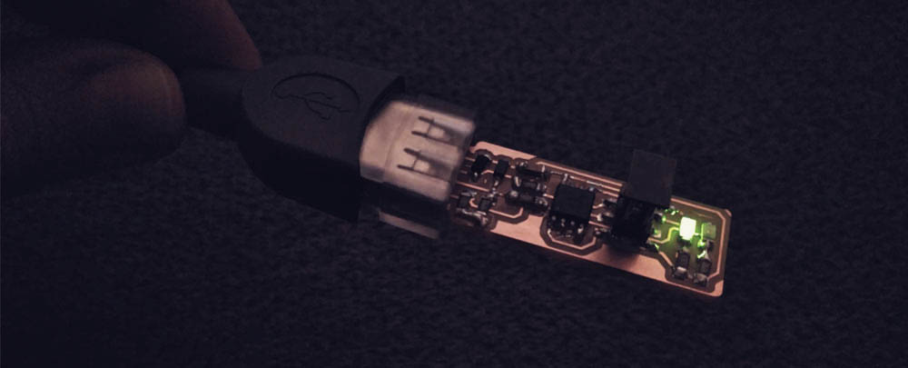
Once the installation is completed and the jumper removed the fabISP is ready!!
Useful links
Milling bits
FR-1 Printed Circuit Board
Fab Modules
Brian PCB tutorial