Computer controlled cutting
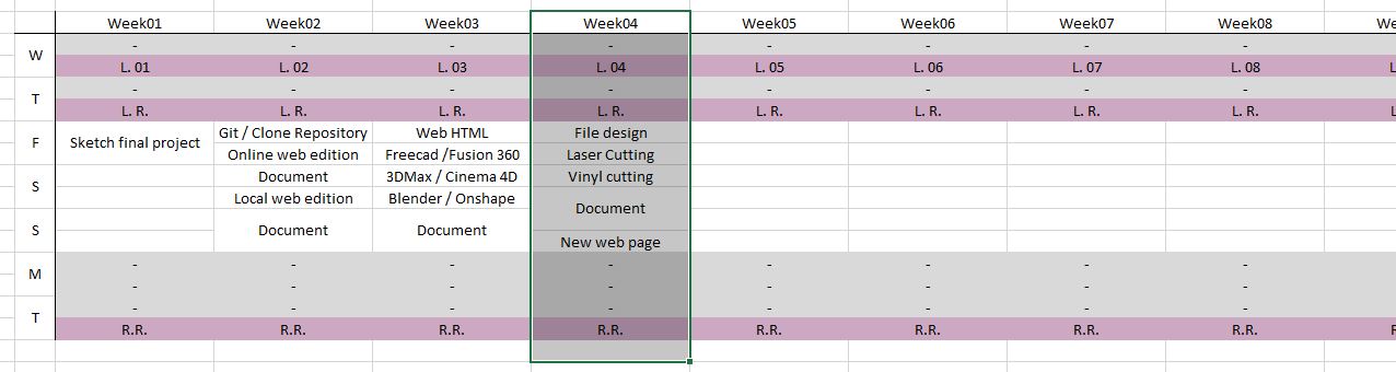
Week 04
Like each week, I made the planning of the assignment. This time I had to take in count that my university and fab lab is closed during the weekend, except for a few hours during Saturday mornings.
Group assignment. Characterizing the machines
I am a remote student and none of my colleagues are in the fab academy, so I did this part of the assigment individualy.
These are the machines, materiales and settings that I used for this assigment:
Laser Cutter: CO2 - Universal Laser System - VLS6.60 (812,8 x 457,2 mm. / 32”x18”)
- Software: VLS Software
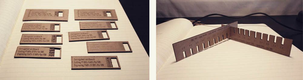
- Settings: Cutting: power 100% speed 60% ppi 500 - Engraving: power 40% speed 100% ppi 500
- Lens: 2.0
- Material: corrugated cardboard 2mm. (press-fit space 1,6mm.)
Vinyl Cutter: Roland CAMM-1 SG-24 (max. width 580mm.)
- Software: Roland CutStudio
- Settings: 15 cm/s 80gf 0,250mm.
- Blade: Roland 45dg.
- Material: Macal 8200 PRO
Parametric design in FreeCAD
For this assignment we are required to create a corrugated cardboard construction kit whith a parametric design. I decided to use FreeCAD (I try it for first time last week for the Computer Aided Design assignment and I loved it!)
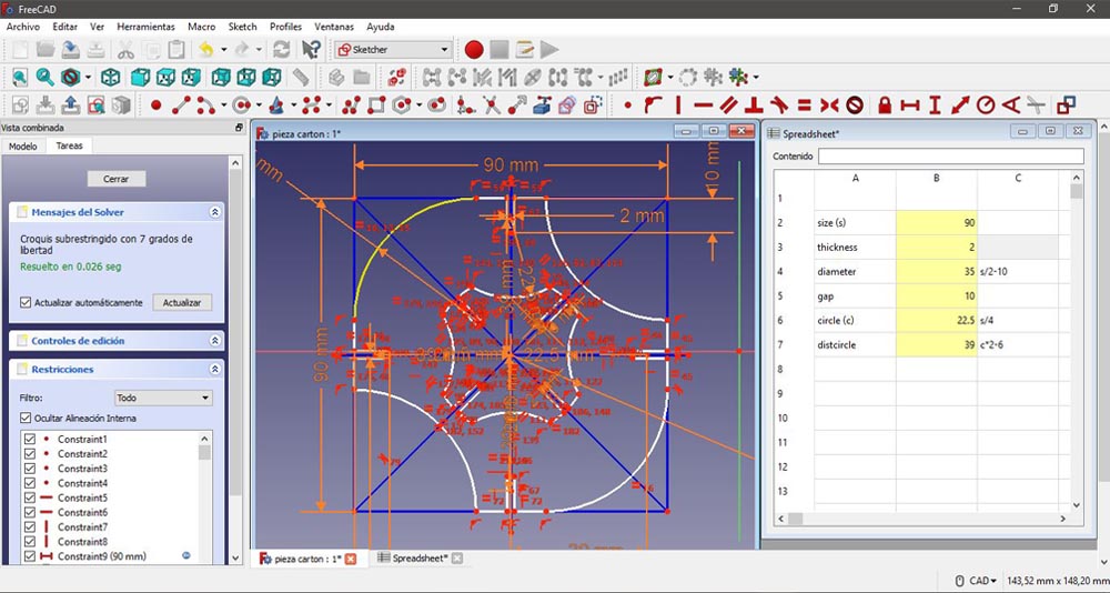
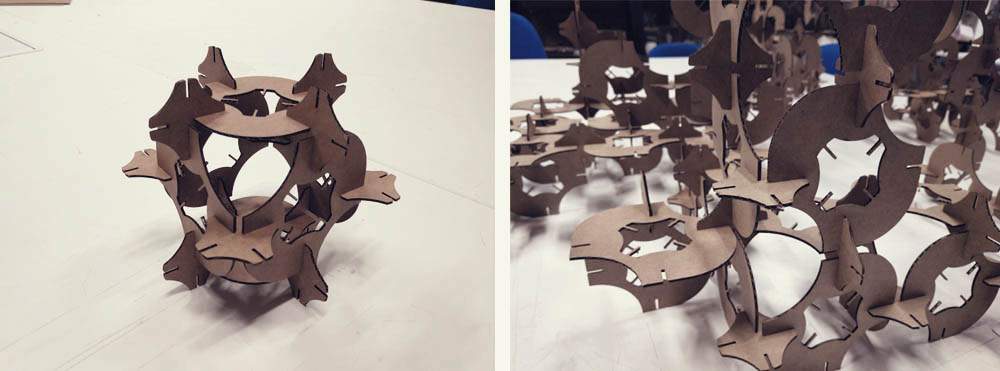
I used the spreadsheet mode to have control over some parameters in my sketch, such us the size of the boundary square, the thickness of the material or the length of the gap. My design is based on a square with the connexions in the middle of each side. Then, to optimize the material as much as possible I made the pieces in such a way that they fit together and I got the join piece from the centre, which also make the structure lighter.
This time the design was much more complex that the previous one and I had some difficulties when I tried to apply some restrictions. I was drawing and applying restrictions at the same time and that gave me problems when I trimmed the unnecessary parts. So I wasted a lot of time repairing the system. What I have learn here is that it is better to draw first the design (whit the basic restrictions) and then apply the rest of the restrictions. That saves a lot of time.
Here you can see how the design change just modifying the parameters in the spreadsheet:
Laser cutting. AutoCAD + Laser software
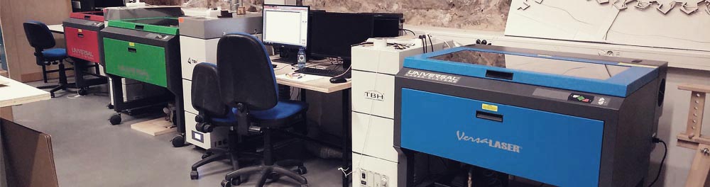
We have three laser cutters in our Fab Lab of the brand Universal Laser System, two are the model VLS6.60 (812,8 x 457,2 mm. / 32”x18”) and the other one is a VLS3.60 (609,6 x 304,8 mm. / 24” x 12”).
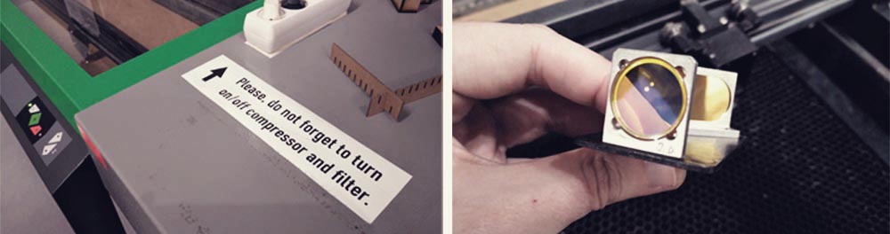
Is funny because the lasers are American, the filters are German and the compressors are Italian. XD
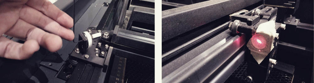
The first thing that I did was to check if the lens was clean and then I turned on the machine, without forgetting to switch on the compressor and filter. The compressor expels pressurized air to help to the laser to be focused. If the compressor is not working instead of having a laser, that line of light, you have a big flame, and that can damage the machine and the material and in the worst cases generate a fire. The filter absorbers the smoke, clean it and throw it away. When the job is done, we have to wait a couple of minutes so the filter can absorb all the fumes which can be dangerous for our health.
Before start cutting the final pieces I wanted to do some tests to choose the perfect settings (speed, power and ppi). After nine tests I decided to use: for cutting: power 100% speed 60% ppi 500; for engraving/rasterizing: power 40% speed 100% ppi 500 . I also wanted to make a “test of thickness” to know, according to the material that I had, which will be the correct thickness for the joins. For this assignment I used cardboard of 2mm and I had to set for the gap 1,6mm so the pieces fit perfectly.
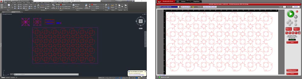
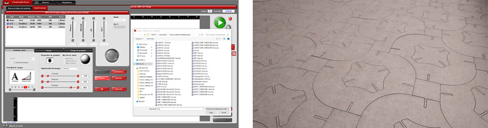
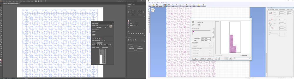
Once this was done I modified the FreeCAD file and I imported the final design to AutoCAD as I am used to use this software to prepare the files to be laser cut. It is very easy, you only have to create some layers with different colours depending on the type of job: a red layer to cut, a blue layer to engrave and a black layer to rasterized. And then you send it (using the plot command) to the software of the laser. Once is there you have to select the material that you are going to use. In our case we already a big list of different materials already set, as our students don’t need to configure the settings each time that they want to laser cut. But, as I have said, I wanted to do some tests to optimize the time and don’t burn the bottom of the cardboard. Finally it took 16 minutes to cut one board of 780x440mm. giving me 46 pieces and its 46 central pieces. And I only wasted the 20% of the board, most of it in the edges.
When I took off the first board I realized that the area in the bottom right corner wasn’t cut well. So I removed the covers of the mirrors and I noticed that the laser wasn’t well centred. So I aligned the laser moving a bit the angle of the first mirror. Once this was fixed I didn’t have problems again.
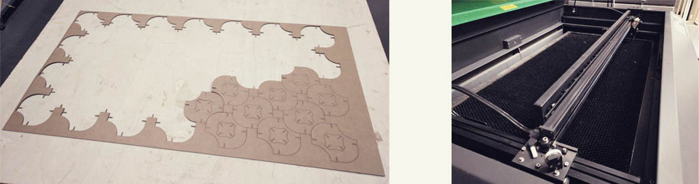
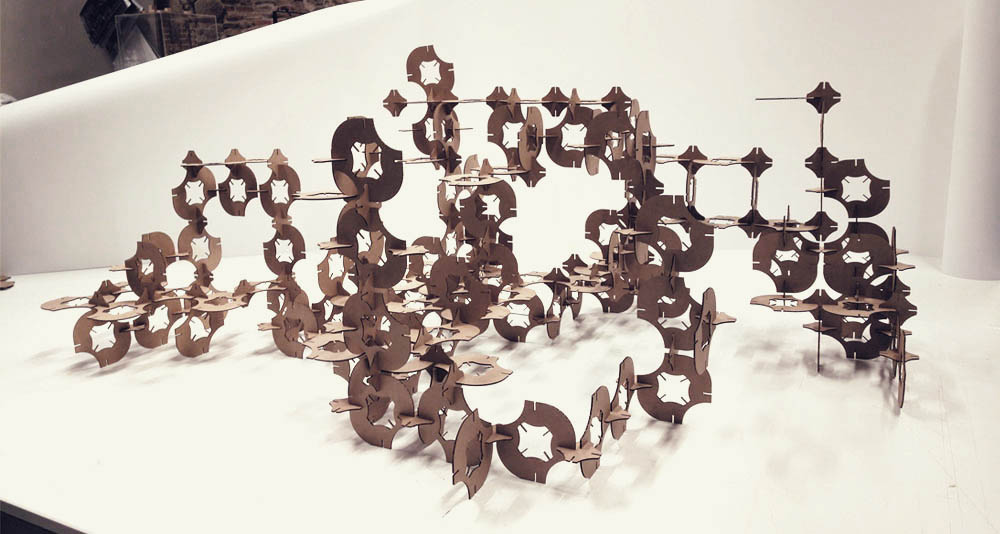
And this is the final result!!
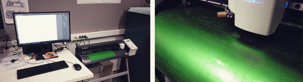
Vinyl cutting. Illustrator + Roland CutStudio
For this second assignment I decided to use as a base the same file that I used for laser cutting and I created a pattern with it. Our vinyl cutting is a Roland CAMM-1 SG-24 and the type of vinyl that I used was Macal 8200 PRO. In this case I prepared the file in Illustrator and I send it to the Roland CutStudio. After a couple of test, I decided to use these settings: 15 cm/s 80gf 0,250mm..
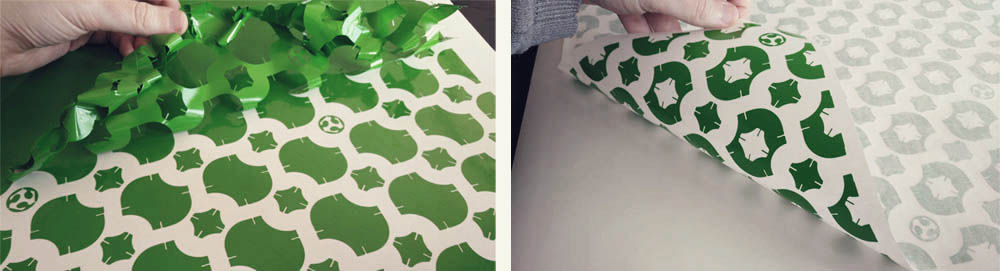
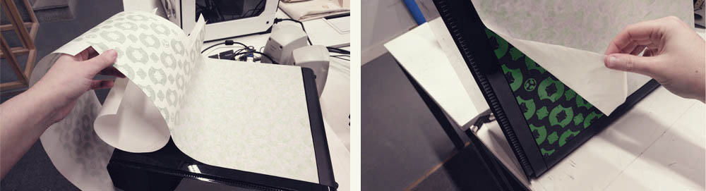
When this was done I started with the weeding process. My file was around 800x350mm. and I took by 20 minutes to remove all the no useful vinyl. Then I used the transfer paper to move all the parts at the same time.
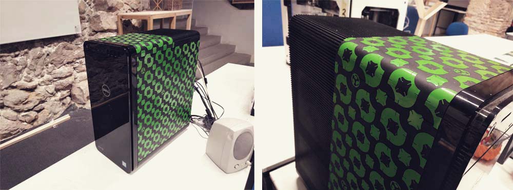
And this is the result! Now my computer is much cooler!! ;)
Files
Find below the files that I made for this assignment. Please do not hesitate to download it!! I hope you enjoy it!!
Parametric design - Freecad
Piece from Parametric design - .pdf
Vynil pattern - .pdf