7. Electronics design
This week I will:
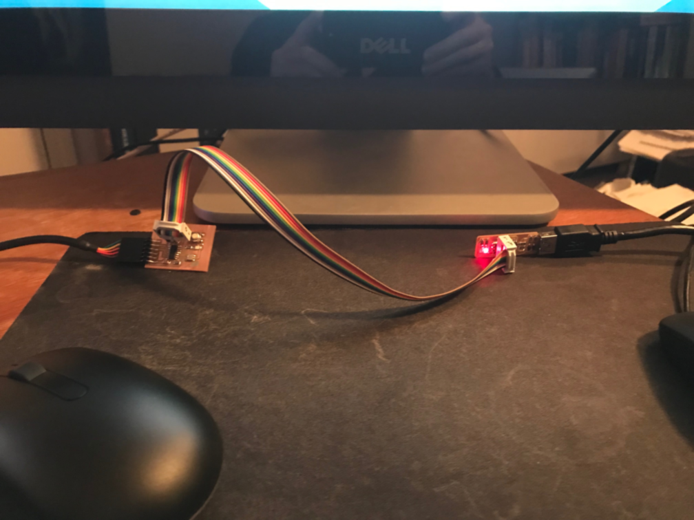
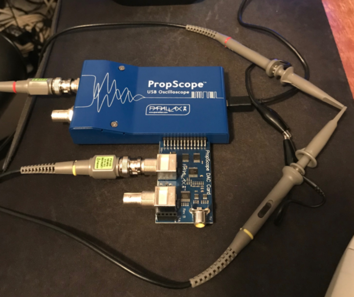
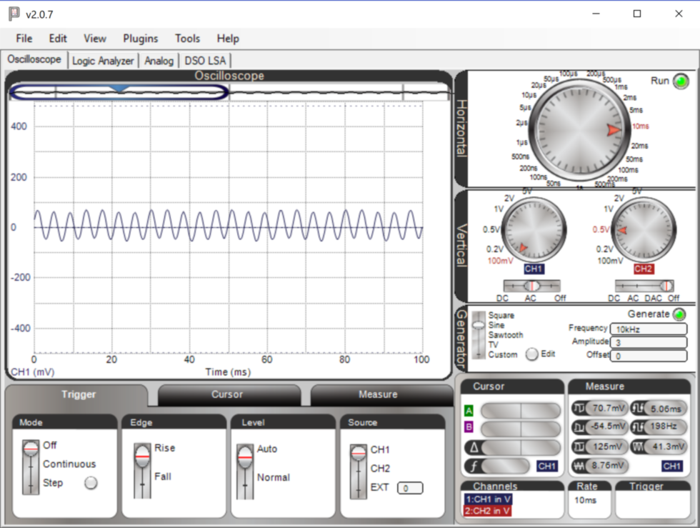
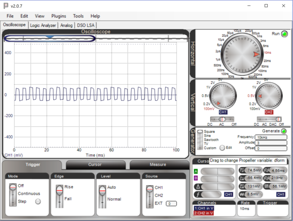
- Use the test equipment in my lab to observe the operation of a microcontroller circuit board (group project)
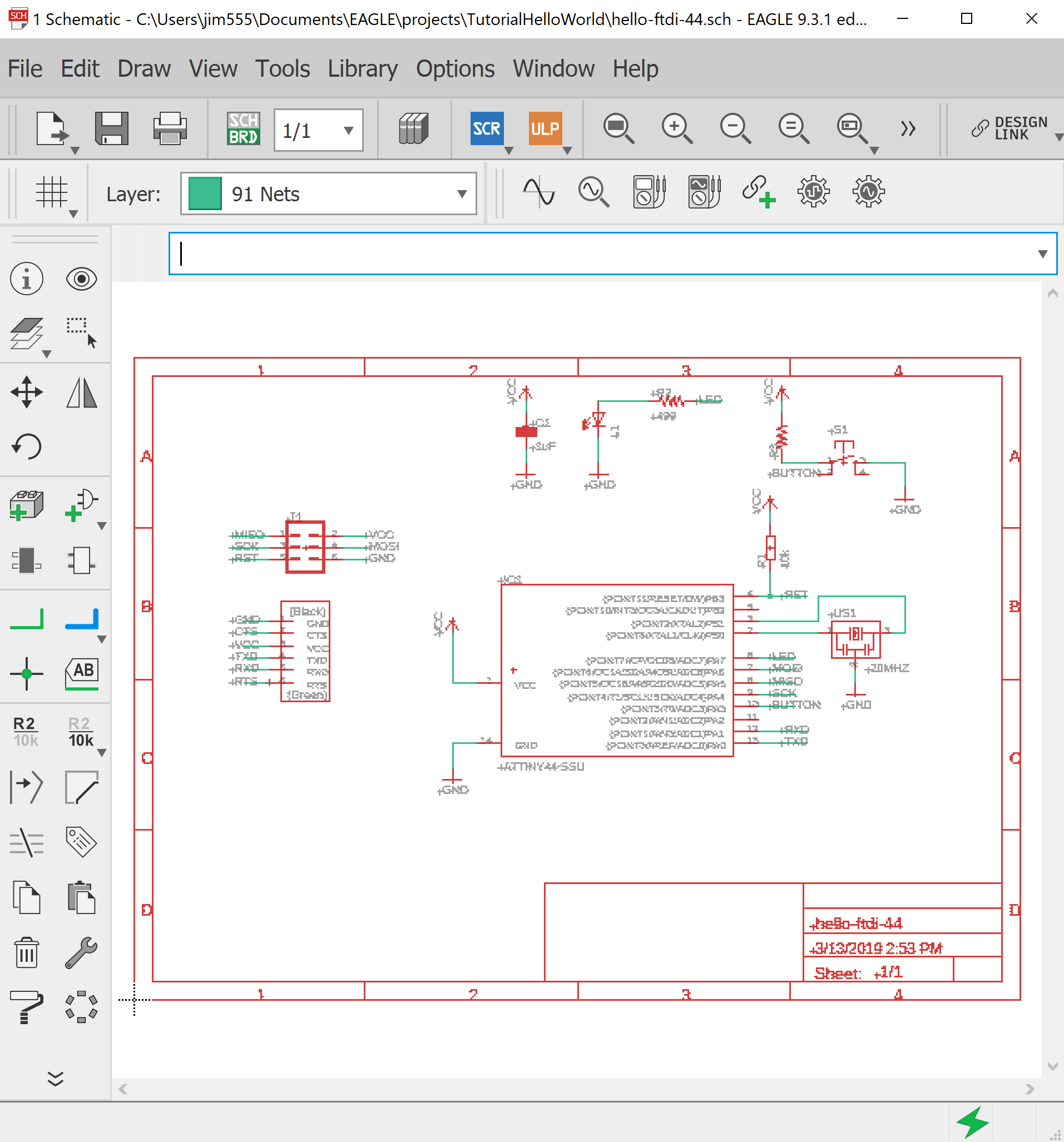
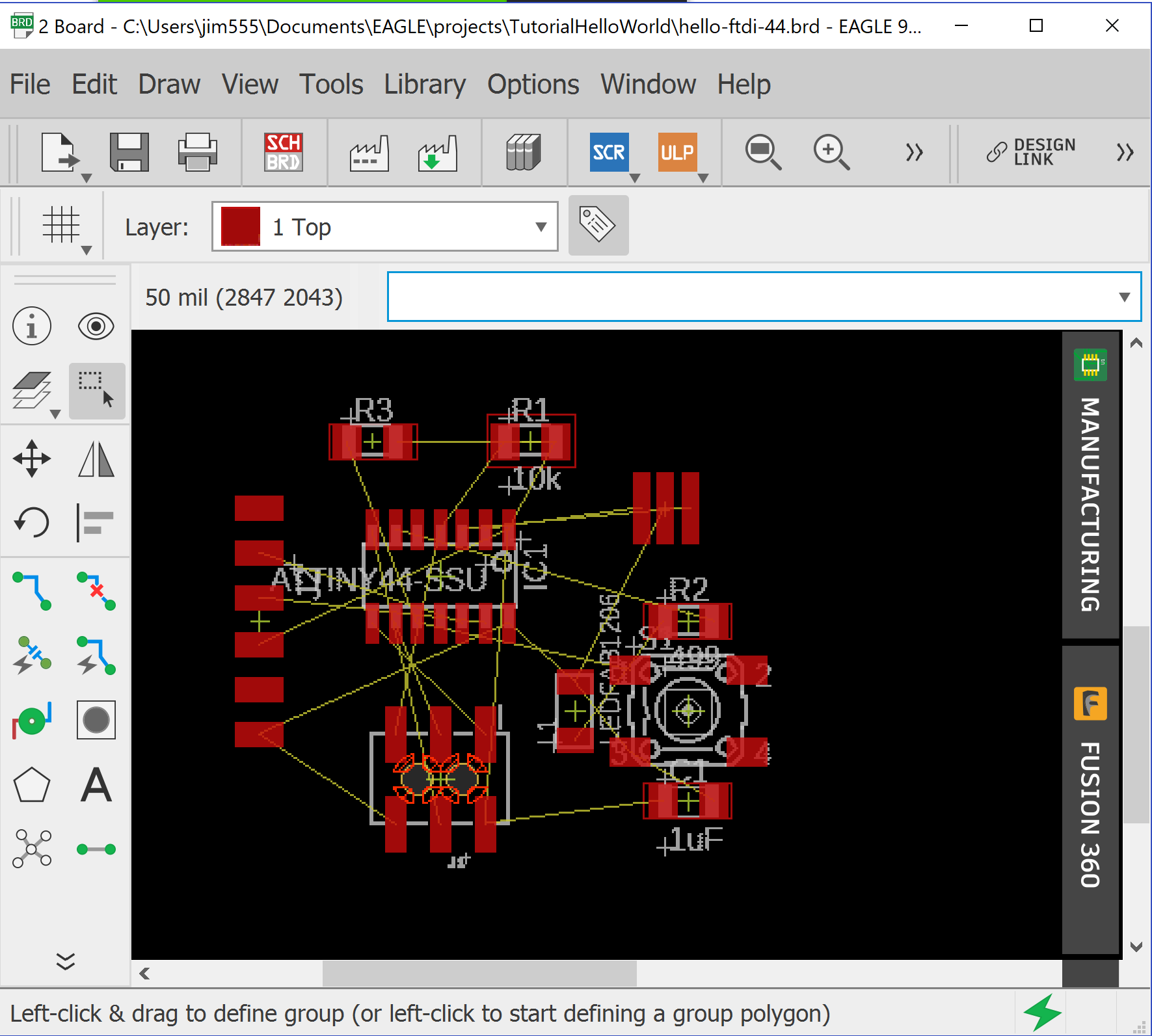
- Redraw the echo hello-world board, add (at least) a button and LED (with current-limiting resistor), check the design rules, make it, test it (individual project)
- extra credit: Simulate its operation. Render it.
Research
Results
- Installed and tested USB Oscilloscope - Parallax Propscope 25MHz

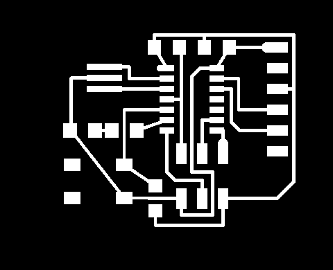
- Installed Eagle PCB design software and designed echo hello-world
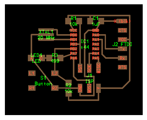
- Used pcb.py|frep.py 250 after completing Eagle design
Code Example
#
# define board. Used Neil's example as a guide, but stuffed every part and
#               made the traces "by hand"
#

w = .015
width = 1.5
height = 1.2
mask = .004
x = 1
y = 1
z = -.005
d = .06

pcb = PCB(x,y,width,height,mask)

IC1 = ATtiny44_SOICN('IC1\nt44')
pcb = IC1.add(pcb,x+.87,y+.77,z)

J1 = header_ISP('J1\nISP')
pcb = J1.add(pcb,IC1.x+.05,IC1.pad[7].y-.22,z,angle=90)

pcb = wire(pcb,w,
   IC1.pad[8],
   point(J1.pad[1].x,IC1.pad[8].y,z),
   J1.pad[1])

pcb = wire(pcb,w,
   IC1.pad[9],
   point(J1.pad[3].x,IC1.pad[9].y,z),
   J1.pad[3])

pcb = wire(pcb,w,
   IC1.pad[7],
   point(IC1.pad[7].x,J1.y+.02,z),
   point(IC1.pad[7].x+.04,J1.y-.02,z),
   point(J1.pad[4].x,J1.y-.02,z),
   J1.pad[4])

pcb = wire(pcb,w,
   IC1.pad[4],
   point(J1.pad[5].x,IC1.pad[4].y,z),
   J1.pad[5])

pcb = wire(pcb,w,
   IC1.pad[14],
   point(J1.x-.01,IC1.pad[14].y,z),
   point(J1.x-.05,IC1.pad[14].y-.04,z),
   point(J1.x-.05,J1.y+.02,z),
   point(J1.x+.05,J1.y+.02,z),
   point(J1.x+.05,J1.pad[2].y-.08,z),
   point(J1.pad[6].x,J1.pad[2].y-.08,z),
   J1.pad[6])

J2 = header_FTDI('J2 FTDI')
pcb = J2.add(pcb,x+width-.22,IC1.y-.0,z,angle=0)

pcb = wire(pcb,w,
   J1.pad[2],
   point(J2.x,J1.pad[2].y,z),
   point(J2.x+.08,J1.pad[2].y+.08,z),
   point(J2.x+.08,J2.pad[3].y,z),
   J2.pad[3])

pcb = wire(pcb,w,
   IC1.pad[13],
   point(IC1.pad[13].x+.105,IC1.pad[13].y,z),
   point(IC1.pad[13].x+.105,J2.pad[4].y,z),
   J2.pad[4])

pcb = wire(pcb,w,
   IC1.pad[12],
   point(IC1.pad[12].x+.07,IC1.pad[12].y,z),
   point(IC1.pad[12].x+.07,J2.pad[5].y+.04,z),
   point(IC1.pad[12].x+.11,J2.pad[5].y,z),
   J2.pad[5])

XTAL1 = XTAL_EFOBM('XTAL1\n20 MHz')
pcb = XTAL1.add(pcb,IC1.pad[4].x-.3,IC1.pad[13].y+.003,z,angle=-90)

pcb = wire(pcb,w,
   IC1.pad[2],
   point(XTAL1.x+.12,IC1.pad[2].y,z),
   point(XTAL1.x+.12,XTAL1.pad[1].y,z),
   XTAL1.pad[1])

#pcb = wire(pcb,w,
#   J1.pad[6],
#   point(J1.pad[6].x,J1.pad[6].y-.08,z),
#   point(XTAL1.x-.04,J1.pad[6].y-.08,z),
#   point(XTAL1.x-.12,J1.pad[6].y,z),
#   point(XTAL1.x-.12,XTAL1.pad[2].y,z),
#   XTAL1.pad[2])

pcb = wire(pcb,w,
   IC1.pad[3],
   XTAL1.pad[3])


R1 = R_1206('R1\n10k');
pcb = R1.add(pcb,IC1.pad[1].x,IC1.pad[1].y+.1,z)

pcb = wire(pcb,w,
   R1.pad[1],
   IC1.pad[1])

pcb = wire(pcb,w,
   J2.pad[3],
   point(J2.pad[3].x+.08,J2.pad[3].y,z),
   point(J2.pad[3].x+.08,R1.y+.06,z),
   point(R1.pad[1].x,R1.y+.06,z),
   R1.pad[1])

pcb = wire(pcb,w,
   R1.pad[2],
   point(J1.pad[5].x,R1.y,z),
   J1.pad[5])

C1 = C_1206('C1\n1uF');
pcb = C1.add(pcb,IC1.pad[14].x,R1.y,z)

pcb = wire(pcb,w,
   IC1.pad[14],
   C1.pad[2])

pcb = wire(pcb,w,
   C1.pad[1],
   point(C1.pad[1].x,C1.y+.06,z))

pcb = wire(pcb,w,
   J2.pad[1],
   C1.pad[2])

S1 = button_6mm('S1\nButton');
pcb = S1.add(pcb,J1.pad[5].x-.4,IC1.pad[7].y-.245,z)

pcb = wire(pcb,w,
   IC1.pad[5],
   point(S1.x+.125,IC1.pad[5].y,z),
   S1.pad[4])

pcb = wire(pcb,w,
   S1.pad[3],
   J1.pad[6])

R2 = R_1206('R2\n10k');
pcb = R2.add(pcb,S1.pad[2].x+.4,J1.pad[4].y,z,angle=-90)

pcb = wire(pcb,w,
   R2.pad[1],
   S1.pad[4])

pcb = wire(pcb,w,
   R2.pad[2],
   point(R2.pad[2].x,R2.pad[2].y-.07,z),
   point(J1.pad[2].x,J1.pad[2].y-.13,z),
   J1.pad[2])

#J2.pad[3],
#   point(J2.pad[3].x+.08,J2.pad[3].y,z),
#   point(J2.pad[3].x+.08,R1.y+.06,z),
#   point(R1.pad[1].x,R1.y+.06,z),
#   R1.pad[1])

LED1 = LED_1206('LED1\nLED')
pcb = LED1.add(pcb,S1.pad[1].x+.05,IC1.pad[7].y,z)

pcb = wire(pcb,w,
   LED1.pad[1],
   point(LED1.x-.055,XTAL1.pad[2].y,z),
   XTAL1.pad[2])

pcb = wire(pcb,w,
   S1.pad[3],
   LED1.pad[1])

R3 = R_1206('R3\n499');
pcb = R3.add(pcb,S1.pad[3].x,IC1.pad[7].y,z)

pcb = wire(pcb,w,
   R3.pad[2],
   IC1.pad[6])

pcb = wire(pcb,w,
   LED1.pad[2],
   R3.pad[1])
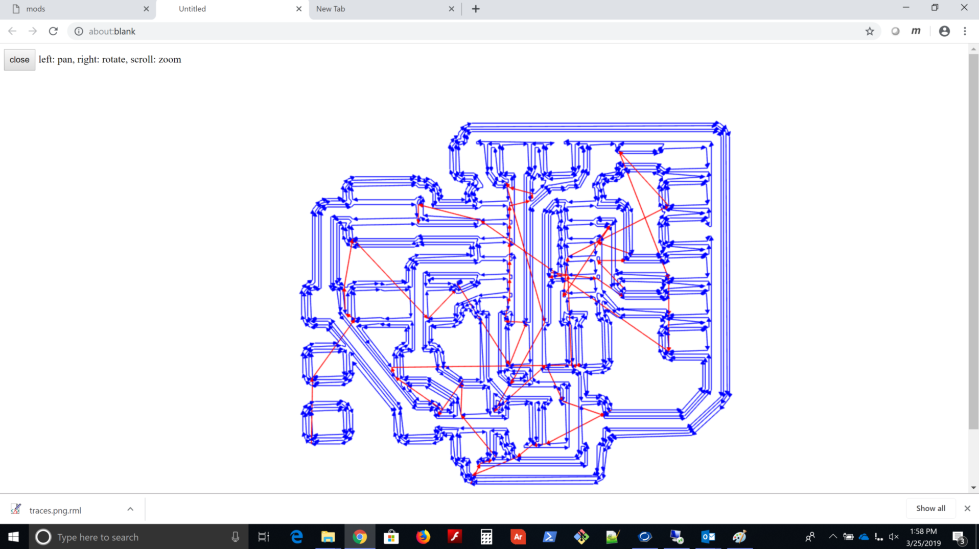
- Used pcb.py and frep.py to “Design It” and generate these images to bring into mods
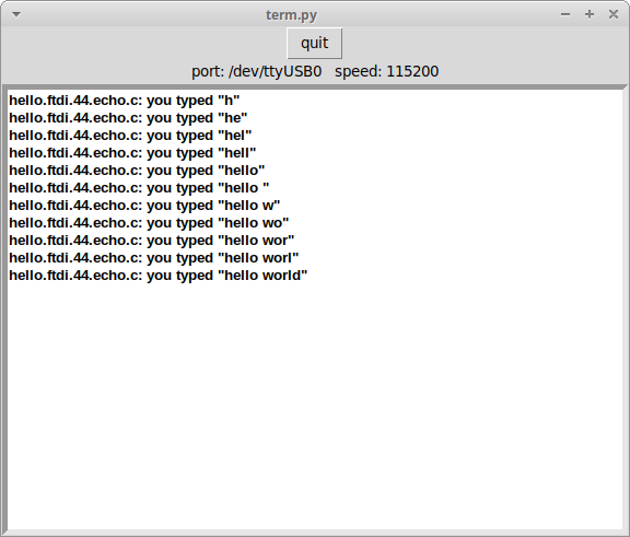
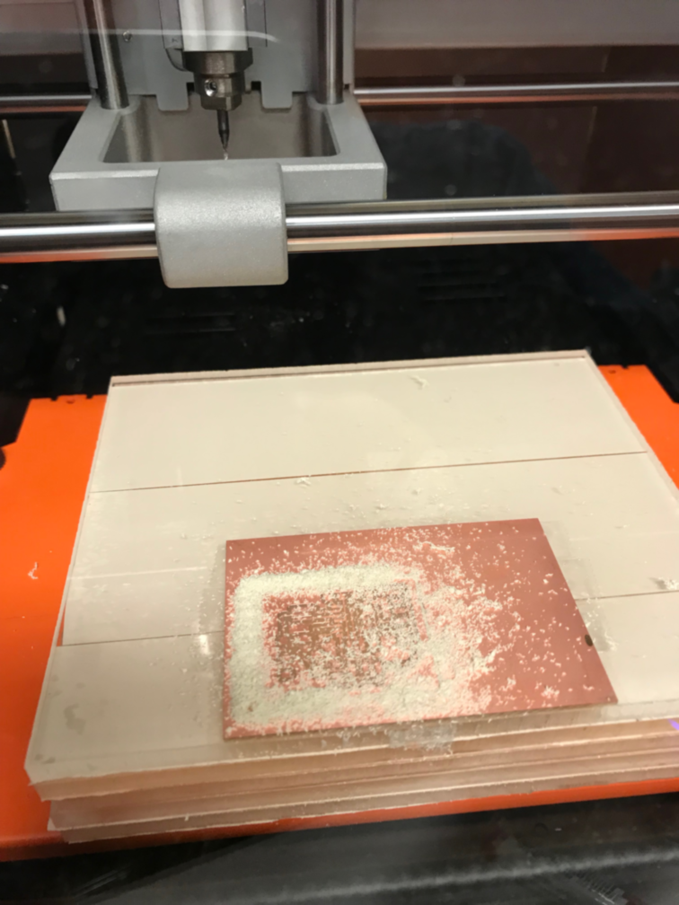
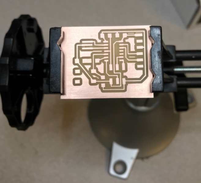
- “Make It”
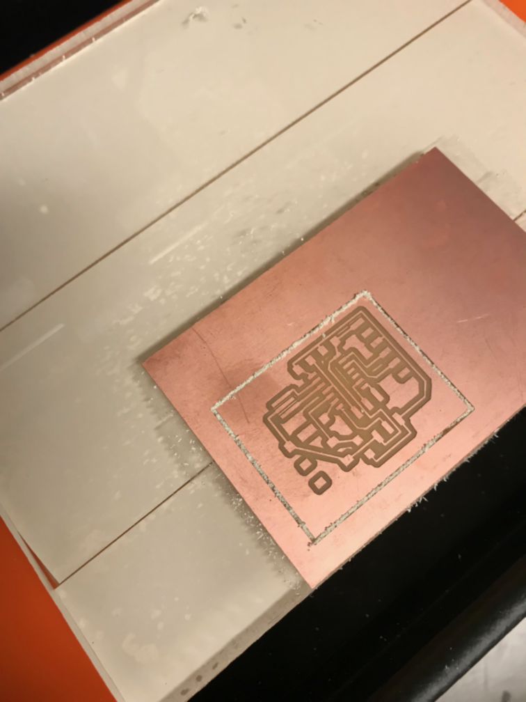
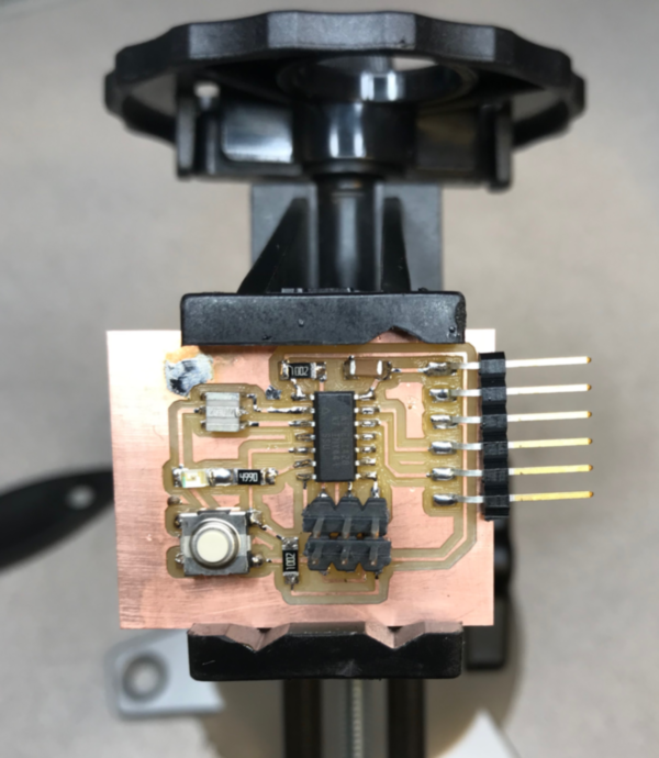
- “Test It”