11. Input devices
Group assignment:
The group assignment can be viewed using this link
Design
I decide to make a temperature sensor board for this week. I followed Neils design to create the board in kicad.
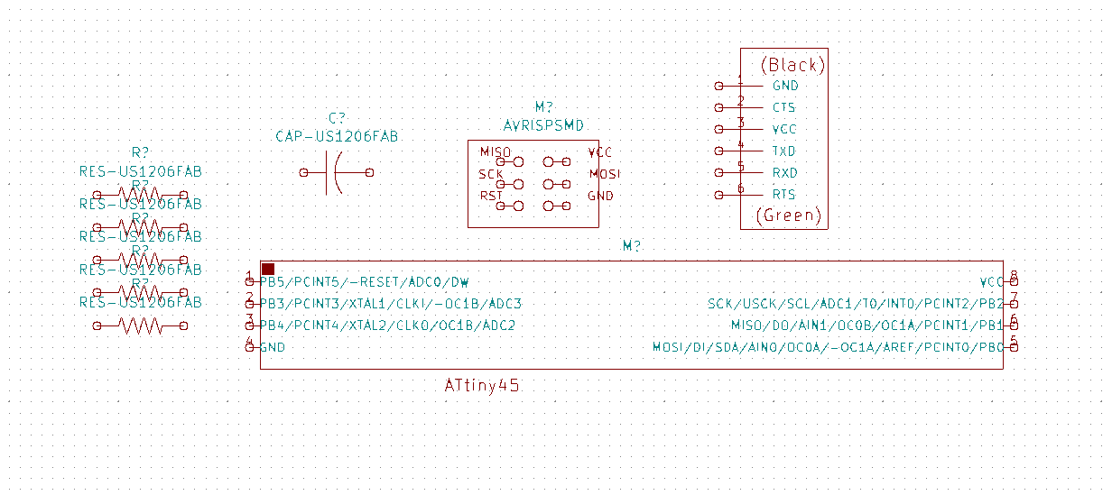
First I added the components
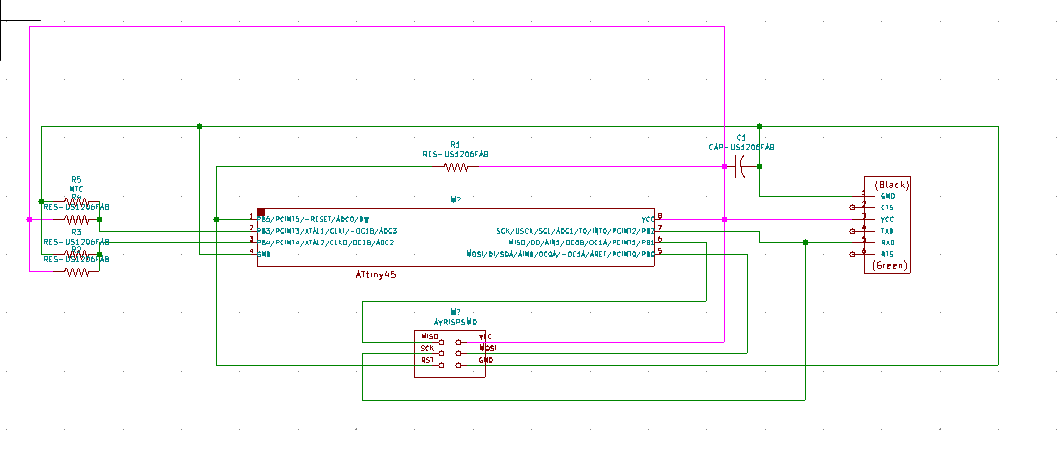
Then make all connections
After that I have to annotate, assign footprints and generate netlist. Then go to pcb design.
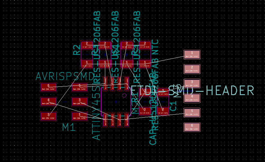
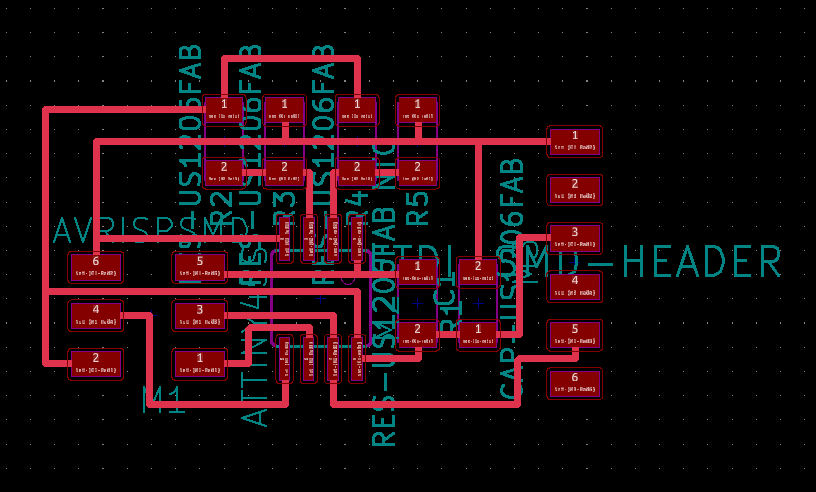
And start making traces
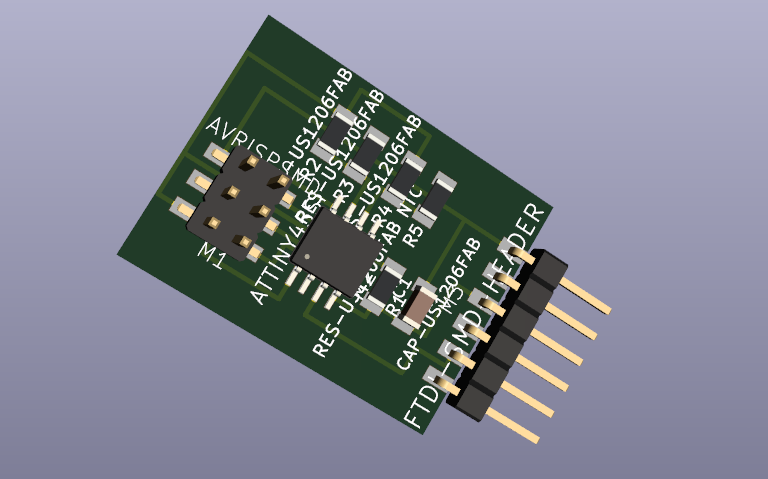
I learned how to make a 3D model of the board with kicad
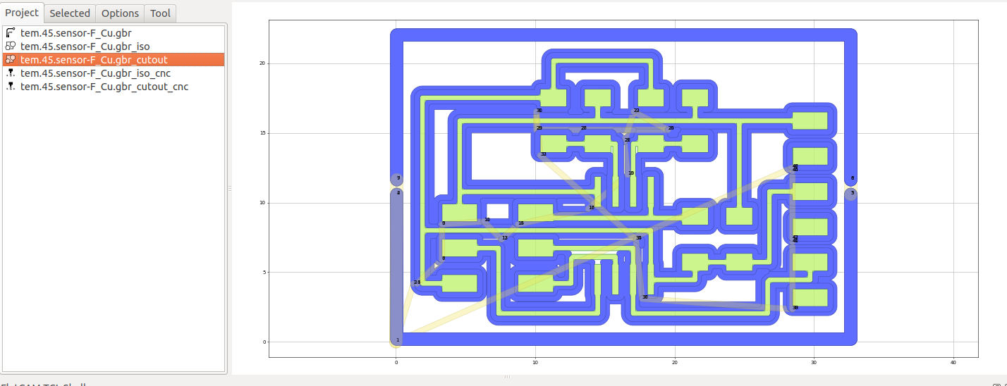
When finish, create gerber files to make gcode in FlatCam
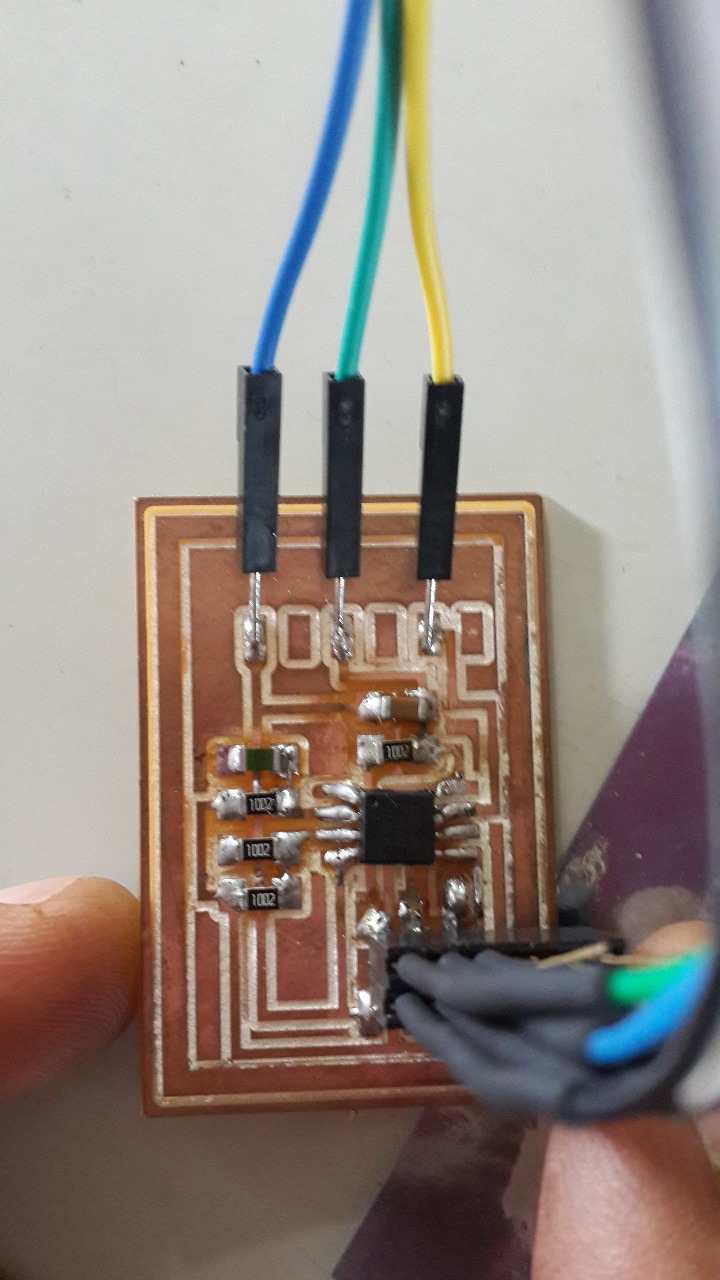
When the board was finished, I connected my programmer to burn the bootloader and test the code for sensing.
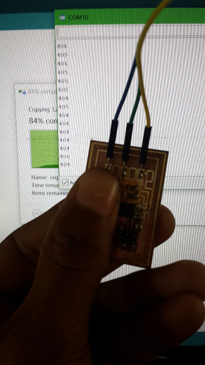
In the serial monitor the changes in the input can be seen
The code uses Neils code for serial communication and PB2 is defined for tx pin.
#define serial_pin_out (1 << PB2)
Then, PB4 and PB3 are set to read the value and compare
| (0 << MUX3) | (1 << MUX2) | (1 << MUX1) | (1 << MUX0); // 20(PB4-PB3)
Because Neils code is more complicated, I also tested another code
Using SoftwareSerial.h for communication, I defined pin 2 as TX pin
#define TX 2
And the resistor attached to the comparisson pin must be defined
#define SERIESRESISTOR 10000
and pin 3 and 4 is defined for input
#define THERMISTORPIN 3
Then, analoRead reads the pins values
reading = analogRead(THERMISTORPIN);
reading2 = analogRead(OTHERPIN);
Finally, the result of the reading is sent over serial
Serial.println(reading);