3d scanning and printing
So it's the 6th week since I begin my fab journey. In this week, I got following assignments,
3D printing
3D printing is any of various processes in which material is joined or solidified under computer control to create a three-dimensional object, with material being added together (such as liquid molecules or powder grains being fused together), typically layer by layer. In the 1990s, 3D printing techniques were considered suitable only for the production of functional or aesthetical prototypes and a more appropriate term was rapid prototyping. Today, the precision, repeatability and material range have increased to the point that 3D printing is considered as an industrial production technology, with the name of additive manufacturing. 3D printed objects can have a very complex shape or geometry and are always produced starting from a digital 3D model or a CAD file.

There are many different 3D printing processes, few of them are given below:
Sourcee(https://3dinsider.com/3d-printer-types/)
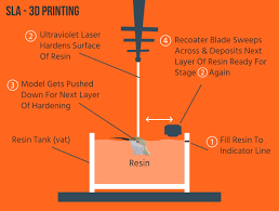
Stereolithography
Stereolithography (SLA) process is based on light curing (photopolymerization) of liquid materials into a solid shape;n this process a vat of liquid polymer is exposed to controlled lighting (like a laser or a digital light projector) under safelight conditions. The exposed liquid polymer hardens. Polymerization occurs when photopolymers are exposed to light when photopolymers contain chromophores, otherwise, the addition of molecules that are photosensitive are utilized react with the solution to begin polymerization. Polymerization of monomers lead to cross-linking, which creates a polymer. Through these covalent bonds, the property of the solution is changed.[29] The build plate then moves down in small increments and the liquid polymer is again exposed to light. The process repeats until the model has been built. The liquid polymer is then drained from the vat, leaving the solid model.
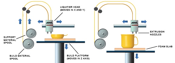
Fused-deposition molding (FDM)
Fused deposition modeling (FDM) technology was developed and implemented at first time by Scott Crump, Stratasys Ltd. founder, in 1980s. Other 3D printing companies have adopted similar technologies but under different names. A well-known nowadays company MakerBot coined a nearly identical technology known as Fused Filament Fabrication (FFF).
With help of FDM you can print not only functional prototypes, but also concept models and final end-use products. What is good about this technology that all parts printed with FDM can go in high-performance and engineering-grade thermoplastic, which is very beneficial for mechanic engineers and manufactures. FDM is the only 3D printing technology that builds parts with production-grade thermoplastics, so things printed are of excellent mechanical, thermal and chemical qualities.
Selective Laser Sintering (SLS)
Selective Laser Sintering (SLS) is a technique that uses laser as power source to form solid 3D objects. This technique was developed by Carl Deckard, a student of Texas University, and his professor Joe Beaman in 1980s. Later on they took part in foundation of Desk Top Manufacturing (DTM) Corp., that was sold to its big competitor 3D Systems in 2001. As was stated previously, 3D systems Inc. developed stereolithography, which in some way is very similar to Selective Laser Sintering. The main difference between SLS and SLA is that it uses powdered material in the vat instead of liquid resin as stereolithography does.

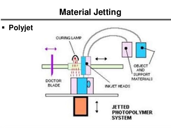
Material Jetting (MJ)
Material Jetting (MJ) works in a similar way to a standard inkjet printer. The key difference is that, instead of printing a single layer of ink, multiple layers are built upon each other to create a solid part. The print head jets hundreds of tiny droplets of photopolymer and then cures/solidifies them using an ultraviolet (UV) light. After one layer has been deposited and cured, the build platform is lowered down one layer thickness and the process is repeated to build up a 3D object. MJ is different from other types of 3D printing technology that deposit, sinter or cure build material using point-wise deposition. Instead of using a single point to follow a path which outlines the cross-sectional area of a layer, MJ machines deposit build material in a rapid, line-wise fashion.
Printing materials
The material used will affect the mechanical properties and accuracy of the printed part, but also its price.Table of materials used in an FDM printer is given below:

source(https://www.3dhubs.com/knowledge-base/fdm-3d-printing-materials-compared)
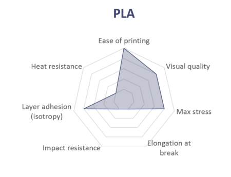
PLA
PLA is the easiest polymer to print and provides good visual quality. It is very rigid and actually quite strong, but is very brittle.
ABS
ABS is usually picked over PLA when higher temperature resistance and higher toughness is required.

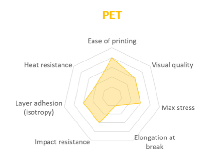
PET
PET is a slightly softer polymer that is well rounded and possesses interesting additional properties with few major drawbacks.
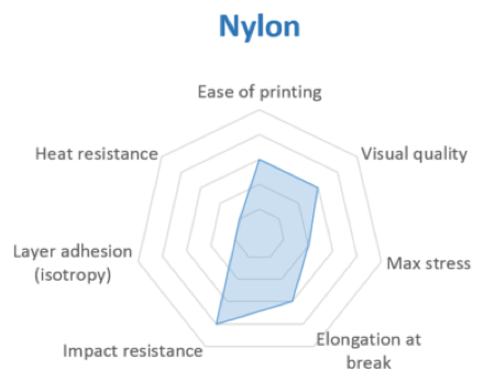
Nylon
Nylon possesses great mechanical properties, and in particular, the best impact resistance for a non-flexible filament. Layer adhesion can be an issue, however.
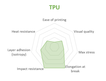
TPU
TPU is mostly used for flexible applications, but its very high impact resistance can open for other applications.
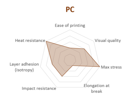
PC
PC is the strongest material of all, and can be an interesting alternative to ABS as the properties are quite similar.
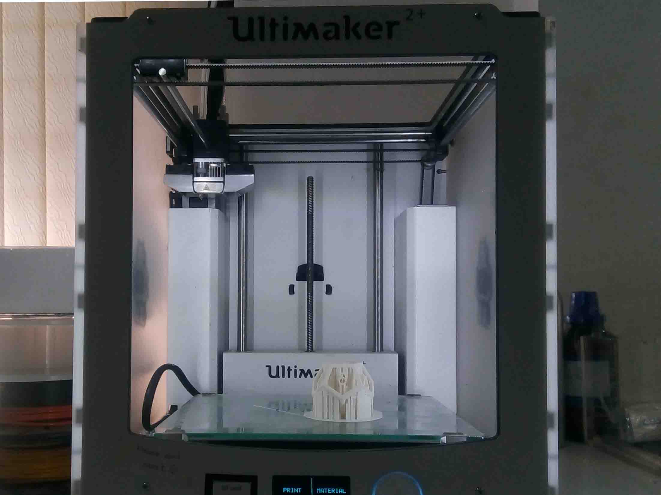
3D printer
In our lab (Fablab Kochi) We have been using Ultimaker for 3D printing. It's very easy to use and very much accurate..
You can get the User's manual Here
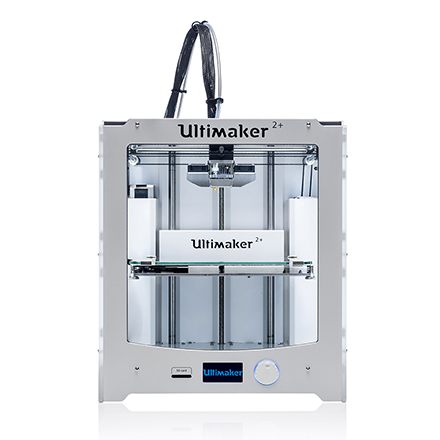
Ultimaker 2+
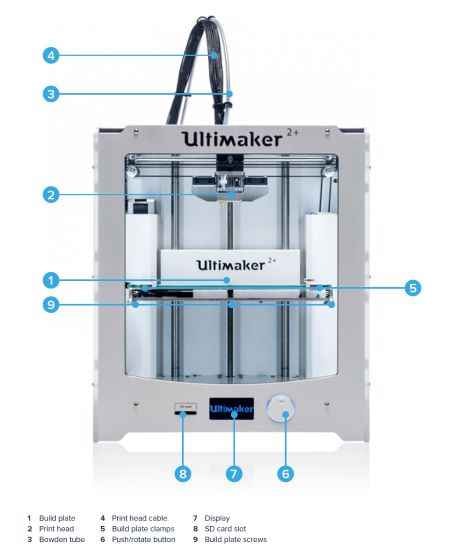
Machine Details
Front
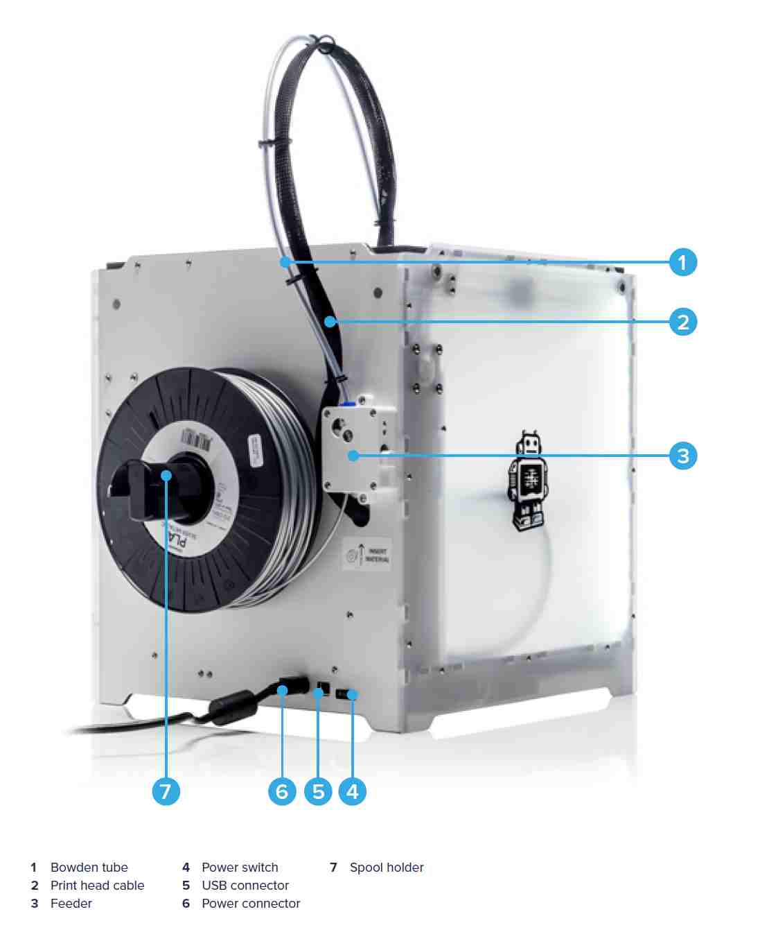
Back
Ultimaker is a 3D printer manufacturer. Their product line includes the Ultimaker 3 family, Ultimaker 2 family and the Ultimaker Original. The company started out as an open-source printer company.Ultimaker 2 is the successor to the Ultimaker Original and was released in September 2013. MAKE magazine classified the Ultimaker 2 as the "best open-architecture 3D printer of 2014" and named it runner-up in the category "Prosumer FFF".
Group Assignment
Design Rules
Introduction
Different 3D printing processes have different capabilities and different design restrictions. In this article we will talk about key design considerations that apply to all 3D printing processes.
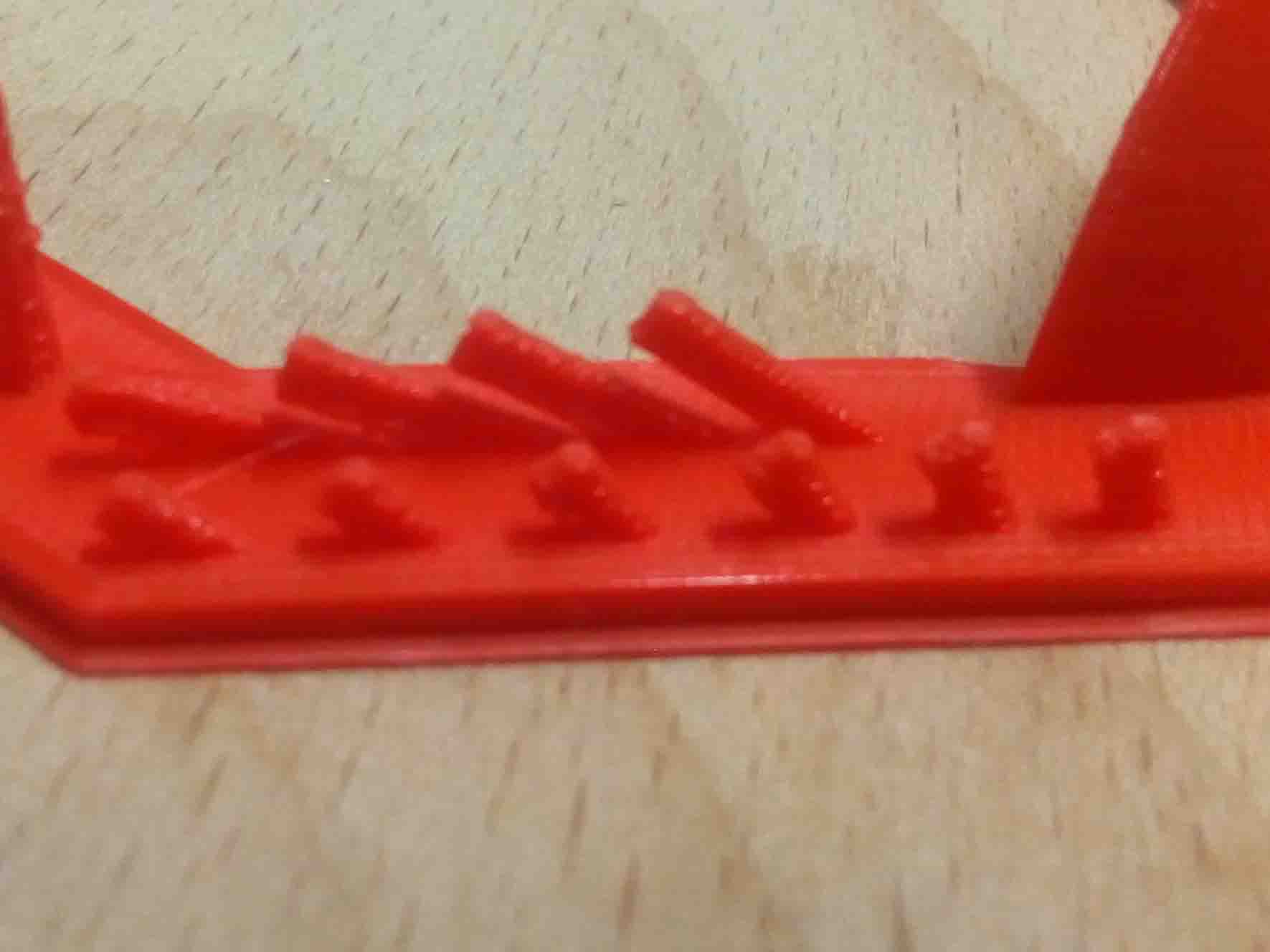
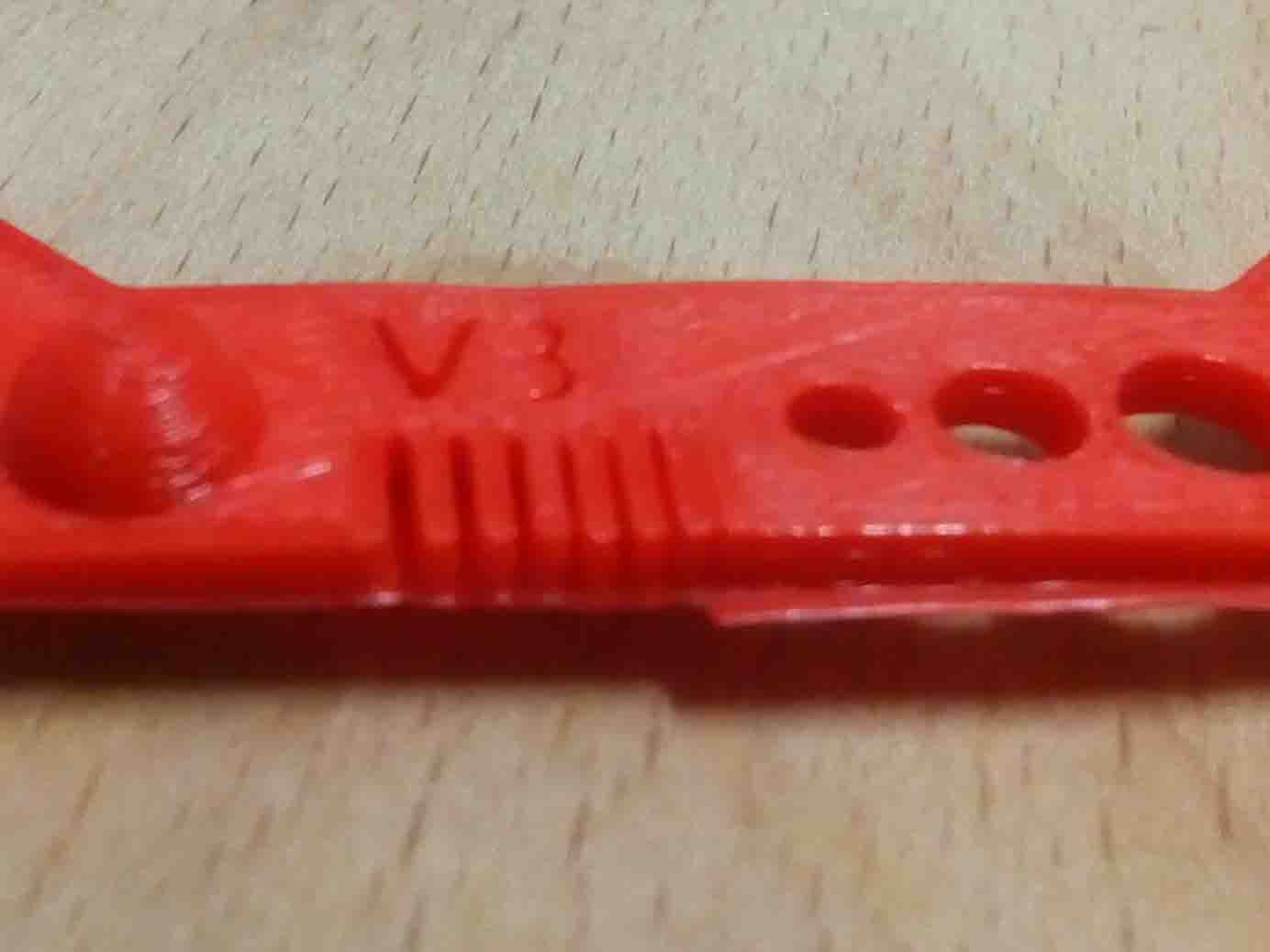
I got a set of tests for checking the design rules. Luckly I find a full set of test from Thingverse
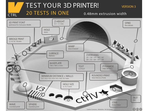
We had help from the thingverse file. So we set the parameters according to it. We set the printing settings as below:
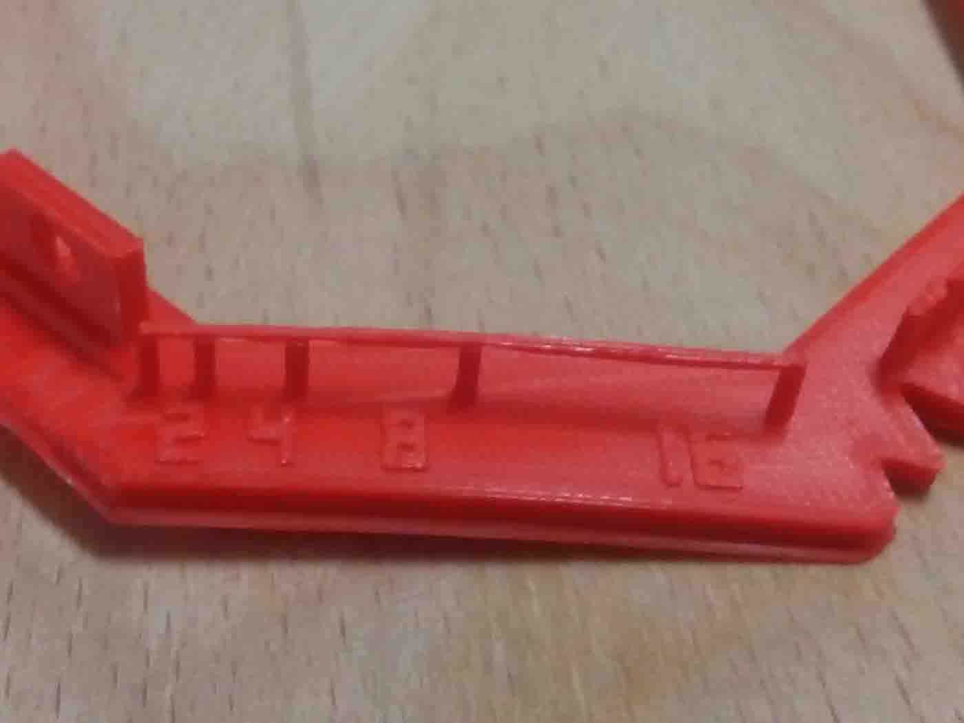
- Rafts:
- - Yes
- Supports:
- - No
- Resolution:
- -0.1mm or higher
- Infill:
- 30%
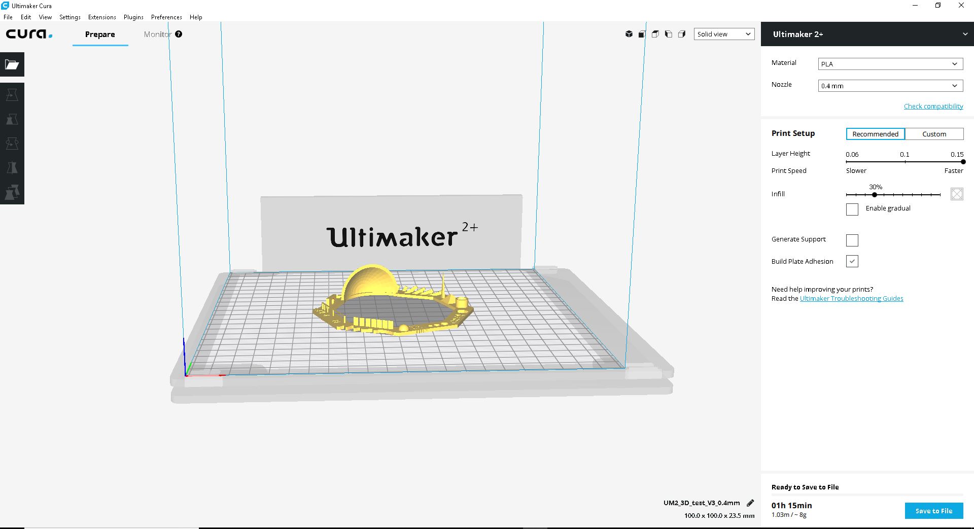
Parameters
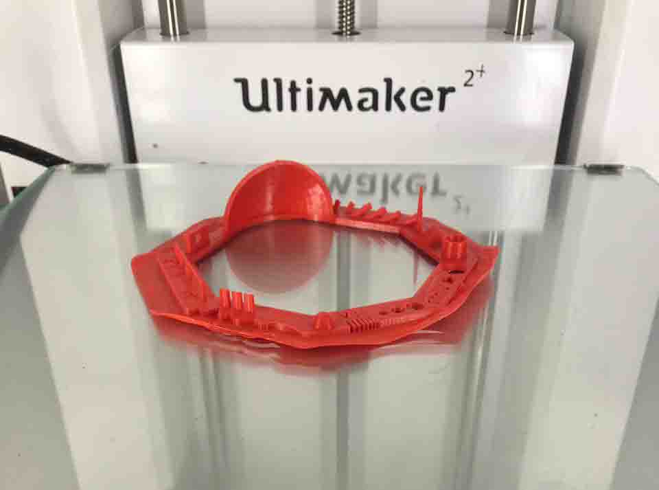
We follow the instructions and put it to print
Digital vs. Physical
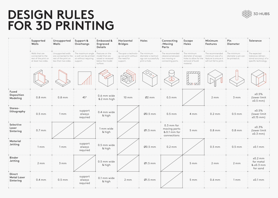
The most important thing to remember while designing for 3D printing is the fact that your digital design will become a physical object. In the digital design environment, there are no laws of physics to adhere to, such as gravity.Each 3D printing process has its own limitations. Here are the most important design considerations that apply to all of them that you should keep in mind:
General Design Consideration for 3D Printing
All 3D printing processes build parts layer-by-layer. Material cannot be deposited onto thin air, so every layer must be printed over some underline material.
Overhangs are areas of a model that are either partially supported by the layer below or not supported at all. There is a limit on the angle every printer can produce without the need of support material. For example, for FDM and SLA this angle is approximately 45o degrees.
It is a good practice to limit the overhangs of a model, as layers printed over support usually have a rougher surface finish.
Also:
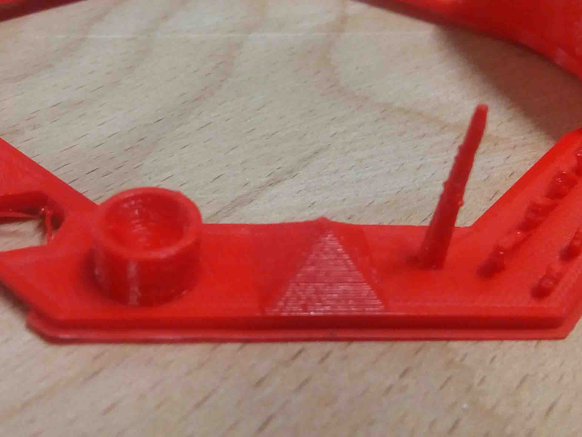
The second thing to keep in mind when designing a part to be 3D printed is wall thickness. Every 3D printing process can produce accurately features that are thin up to a certain point.
For example, imagine you are an engineer who designs hang gliders for a living. You have come up with a great, new design that you have decided to 3D print scaled down for testing. 3D modeling programs allow you to model the sailcloth of the wing, but you would encounter problems when you would try to 3D print it, as its thickness would be extremely small.
As a good practice, always add thickness to your models. Walls with thickness greater than 0.8 mm can be printed successfully with all processes.
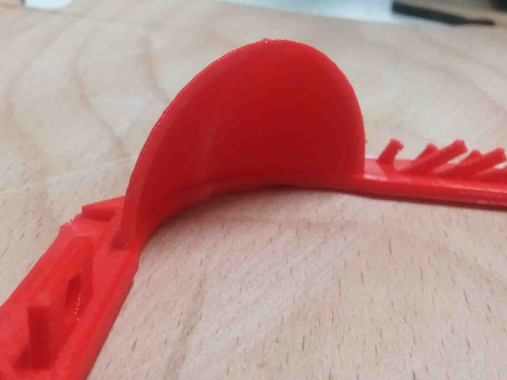
Something that is often easily overlooked while designing a 3D model is the fact that the materials used for 3D printing undertake physical change: they are melted, sintered or scanned with a laser and solidified. The heating and cooling of material can cause the parts to warp while printing.
Large, flat surfaces can be especially prone to warping. Warping can typically be avoided by using correct machine calibration and having adequate surface adhesion between your part and the print bed. Your Hub will be able to offer more advice on design techniques that can be used to minimize the likelihood of warping.
A good practice is to avoid large flat surfaces and add rounded corners to your 3D models.
When you are creating a 3D model with intricate details, it is important to keep in mind what is the minimum feature size each 3D printing process can produce. The minimum level of detail is connected to the capabilities and mechanics of each 3D printing process and to the selected layer height.
The process and materials used will have an impact on the speed and cost of your print, so determining whether smaller details are critical to your model is an important design decision.
Source (https://www.3dhubs.com/knowledge-base/key-design-considerations-3d-printing#/process-specific-guidelines)
3D Designing
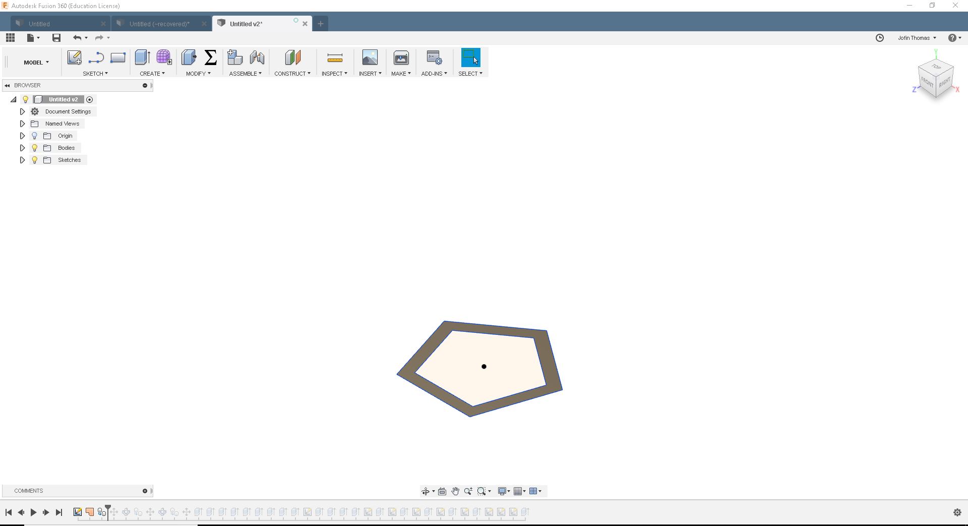
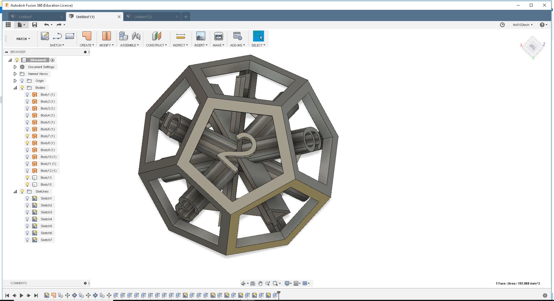
Assignment was Design and 3D Print that could not be made subtractively , So I have designed a dodecahedronal dice In Fusion360. For that first I made a pentagon and made a cut out using "Patch" from the menu.
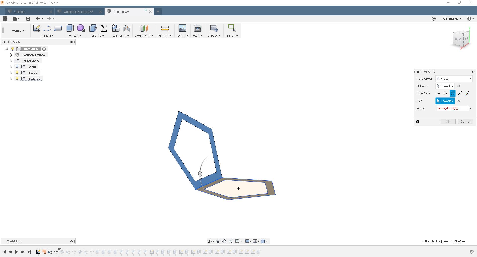
I select and copy the face. Then paste it on the first body. Now I rotate it using the formula "acos(-1/sqrt(5))"
I repeat the same processes and finish up the dodecahedron
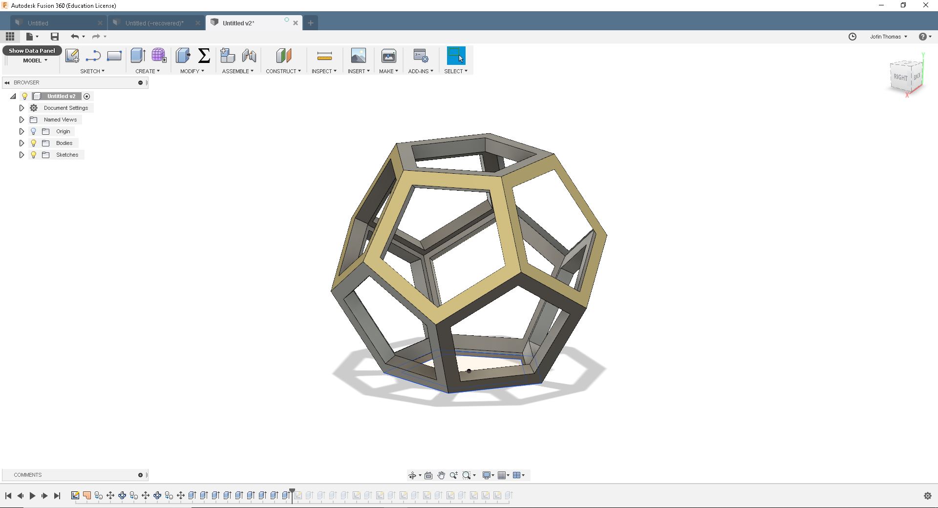
I needed a solid piece. For that I return to "Model" and extrude each body with the thickness of 10mm. I had make sure that each body will join with an other
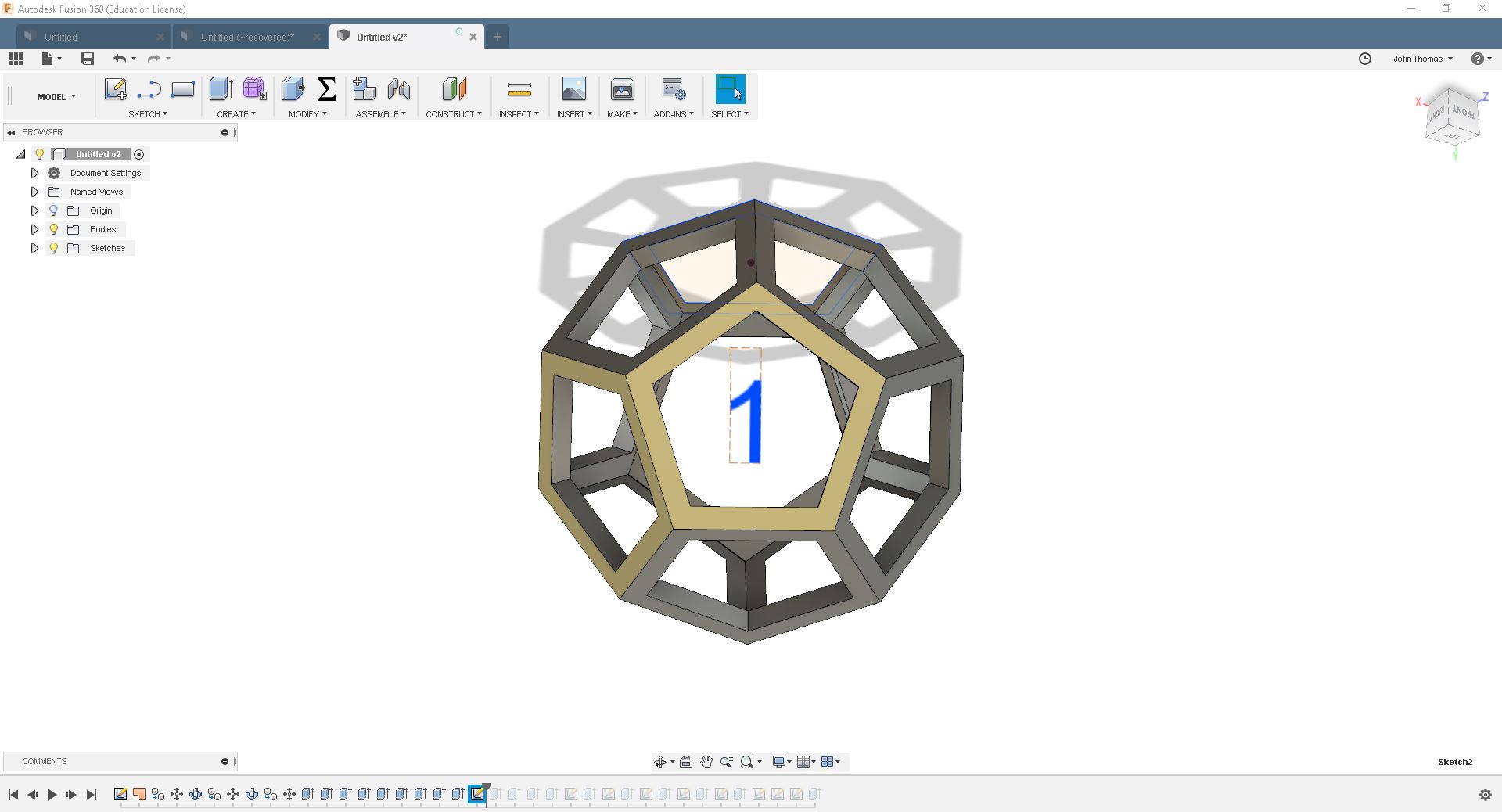
For creating the digit part, I select new sketch and selected a face of the dodecahedron. Drew number 1 and extrude it to the end of the opposite face of rhe dodecahedron. I repeat the same process for the next 5 digits as well. It looked like below:
Now I have to make it a .stl file. For that I clicked "3d Print" under "Make" option in menu.Then a box pops up. Select the shape and click "Ok"
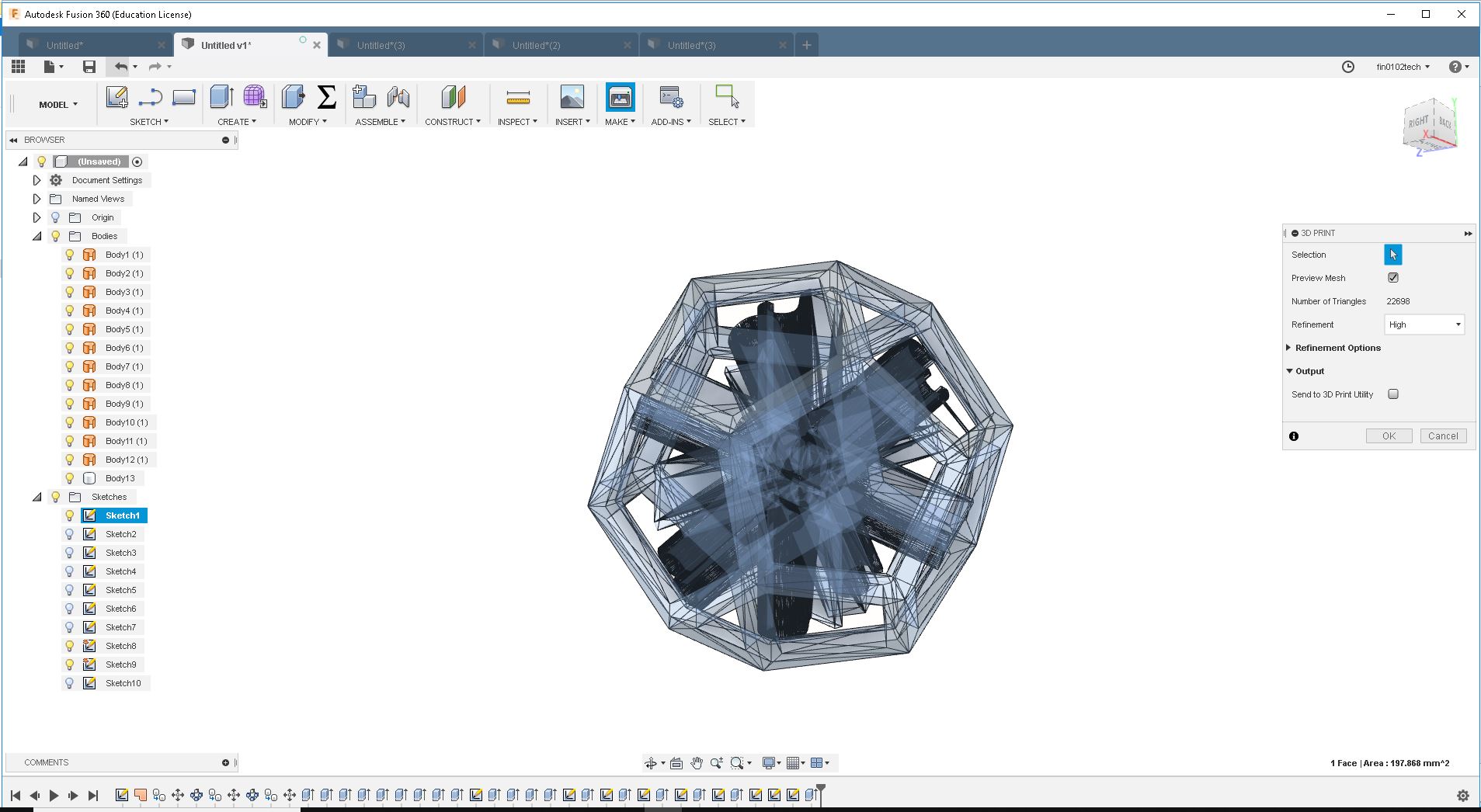
Now save the .stl file in desktop and open "Cura"
You can download the file Here
Cura
Cura is a slicing tool for 3D printers(Especially for Ultimaker), which used to add parameters and export G-Code for printing.
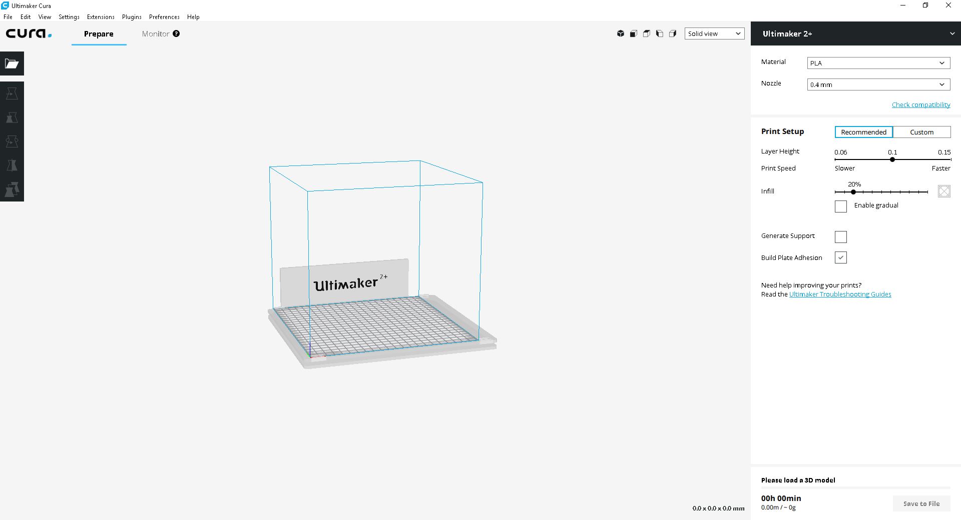
Here we load the .stl file into cura. Now we have to set the values for ultimaker 2+ and add supporting materials to counteract defects.
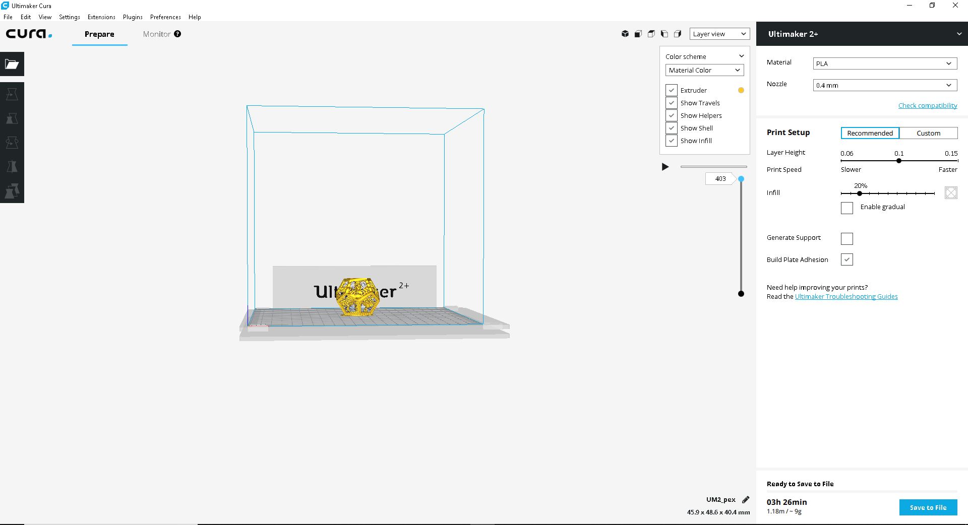
Now export the G-code to SD card and put into Ultimaker
Printing
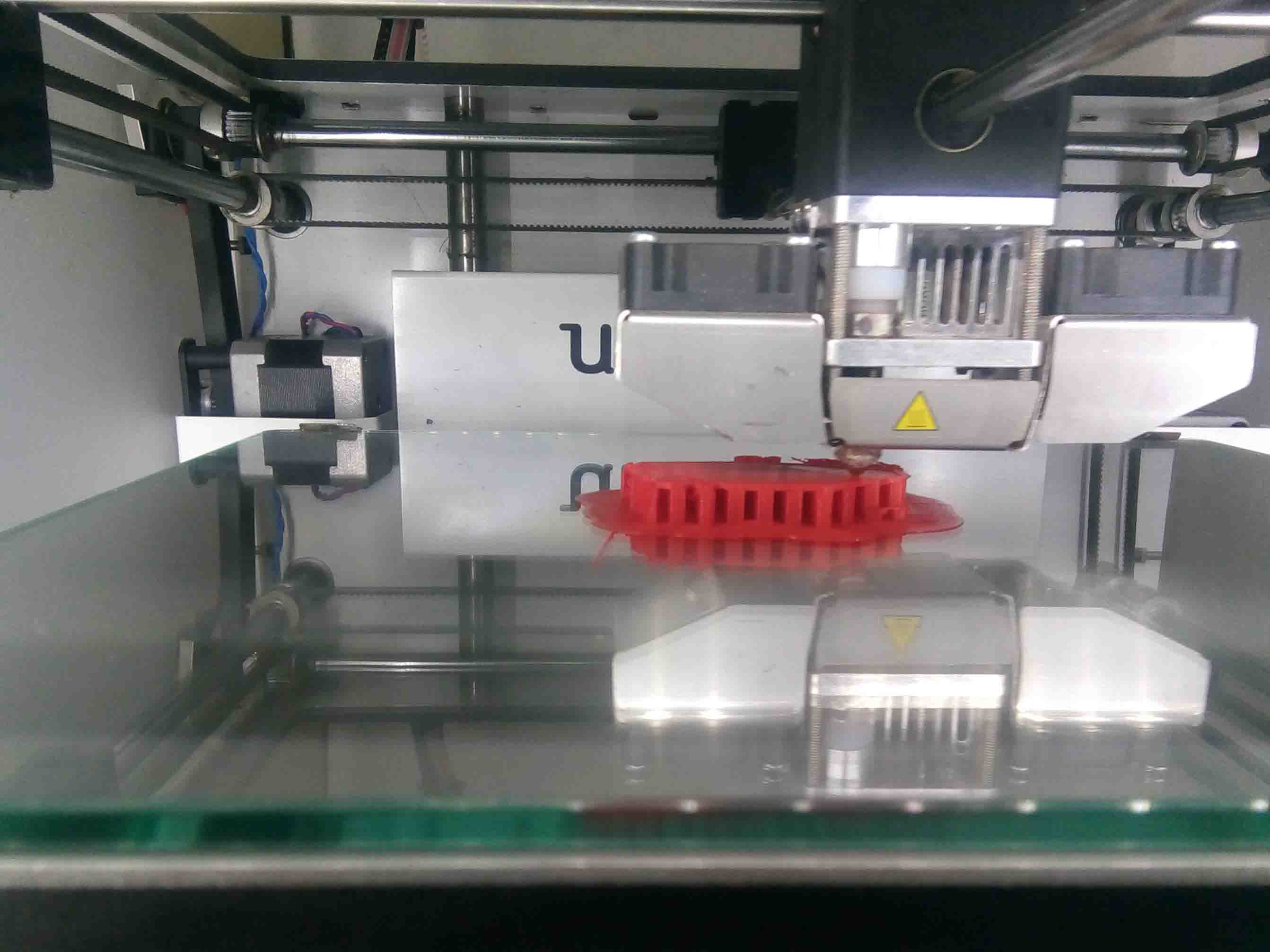
So now we are going physicaly print the design using an Ultimaker 3d printer. For that we need insert the SD card into the SD card slot in the Ultimaker. You can see the details like in following display..
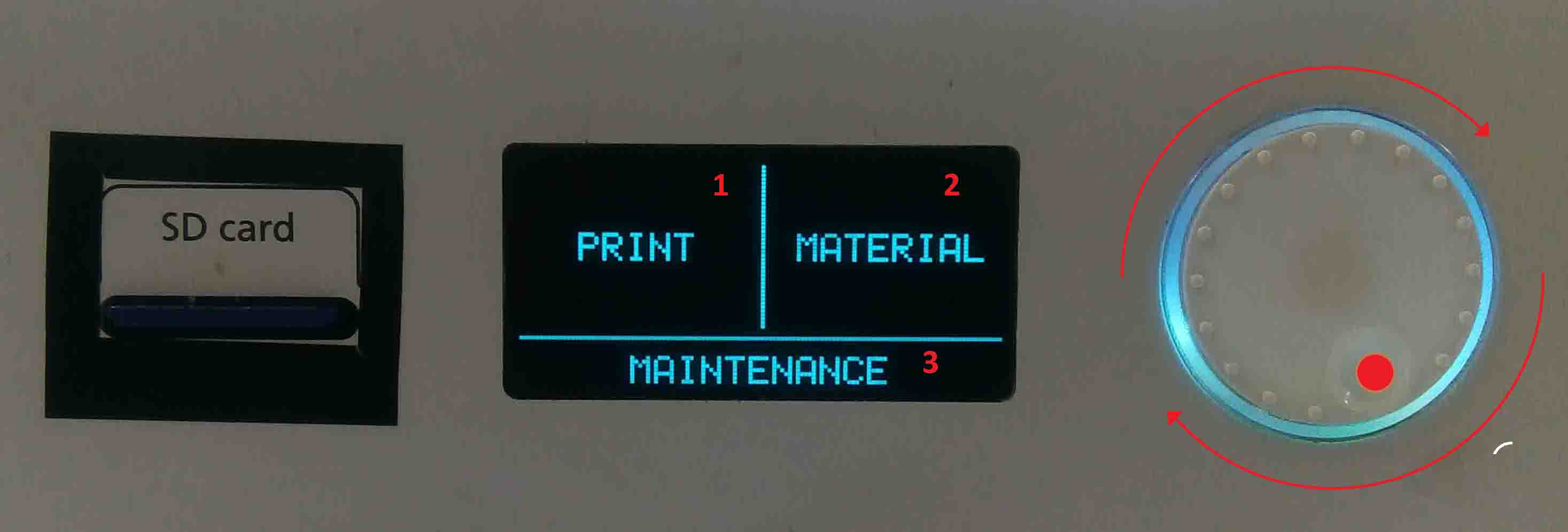
In the display, There are three options:
- Material
- Maintenance
Here we can select each options using the "push-rotate" button. Now we need to give the print command using the push rotate button.
- Select and press "Print"
- Select UM_pex
- Wait for the bed to heat
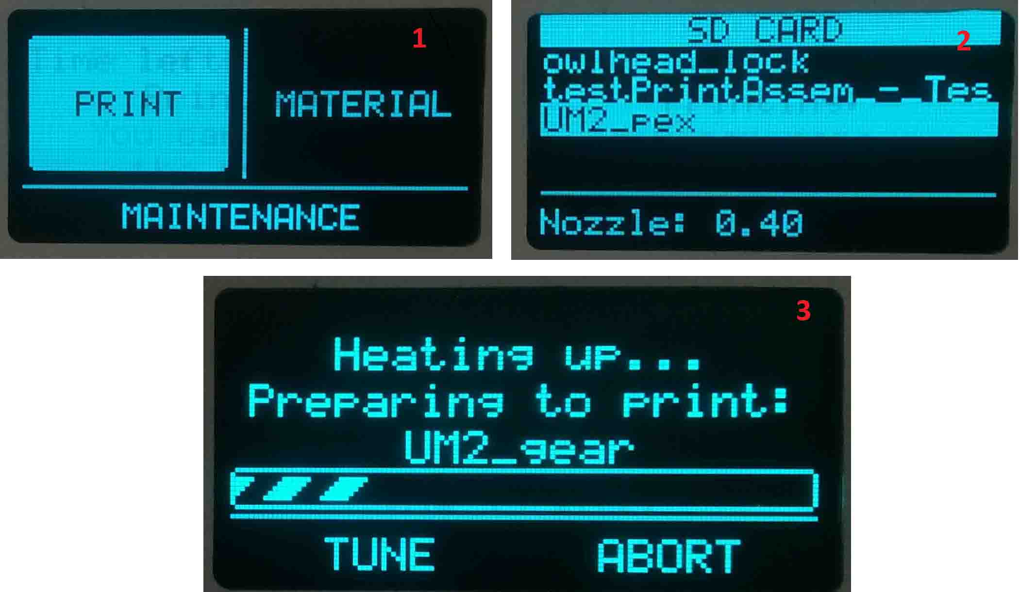
The printer starts to print the file. It took almost 6 hours to get the print ready.
The printed structure was contained lot an dlots of supporting material. It intially lood like below when we took it out of the printer.
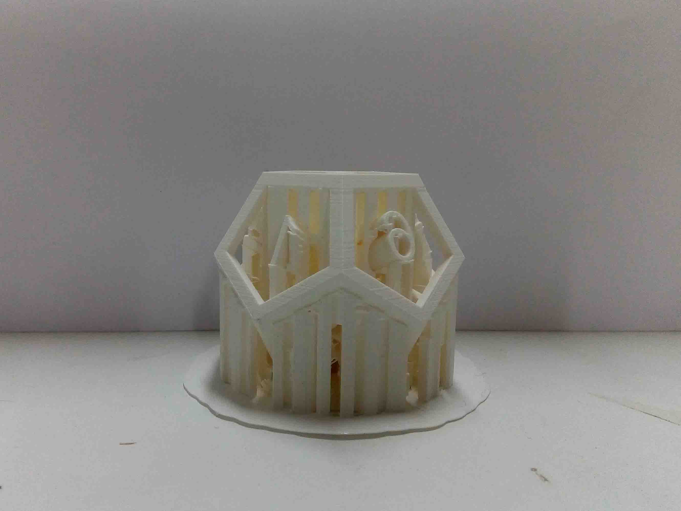
I had to remove lots of suporting materials. For that I used some cutters and knifes.
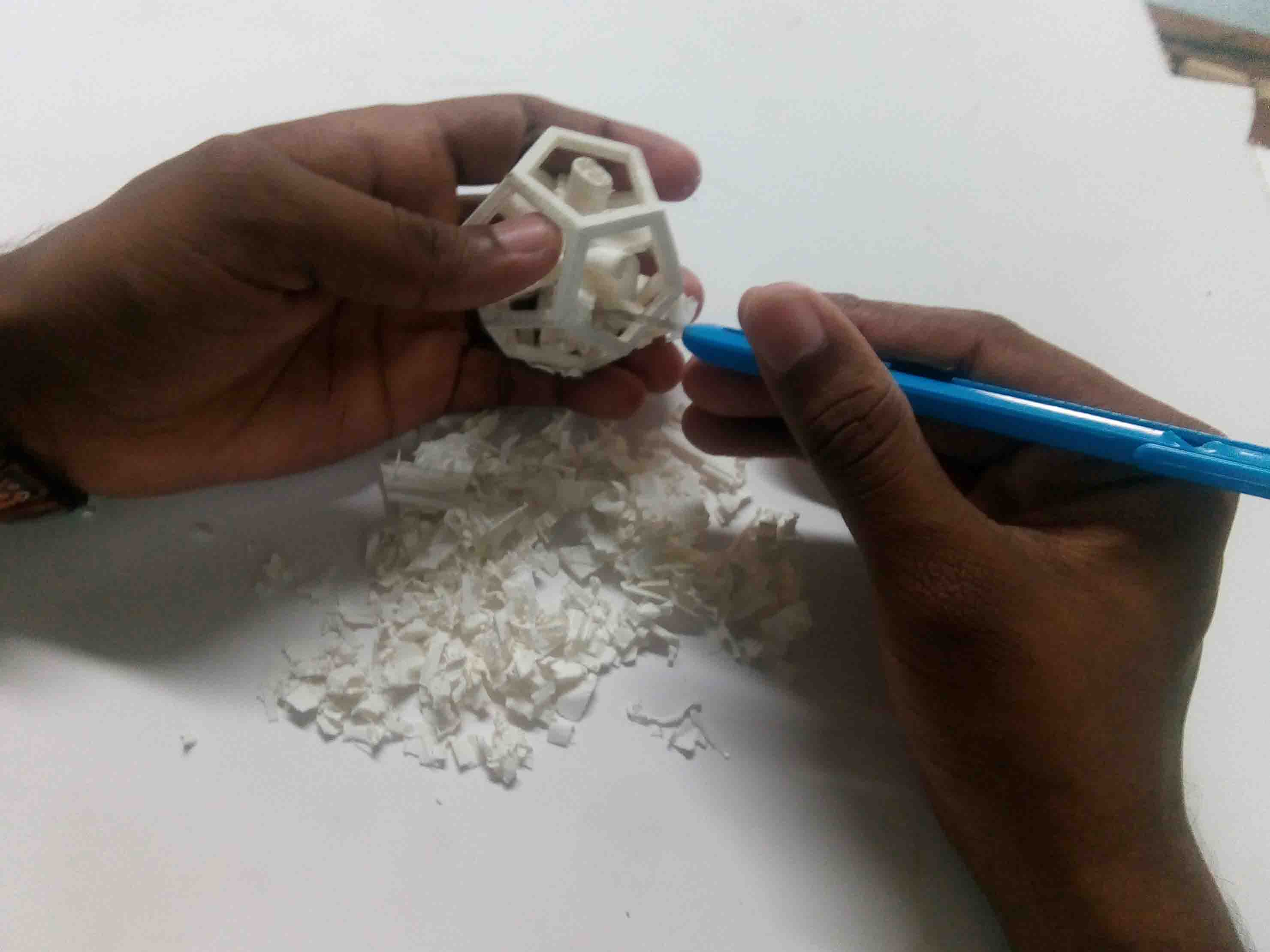
The design was liuttle complex. So I couldn't remove all of the suporting materials. It finally looked like below.
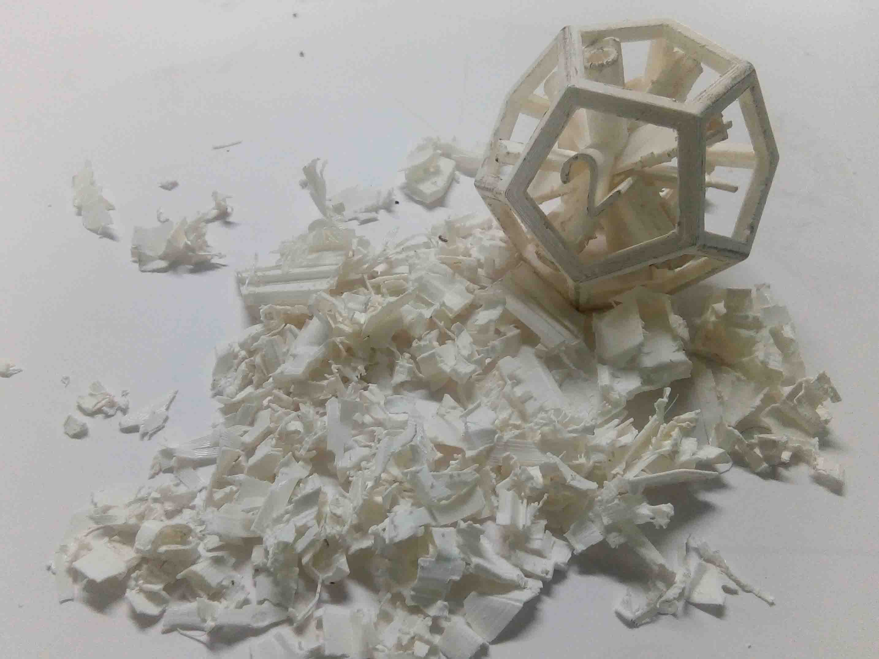
The numbers inside the dodecahedron moved indepentantly after removing the suporting materials. Now we can what mean by 3D scanning...
3D Scanning
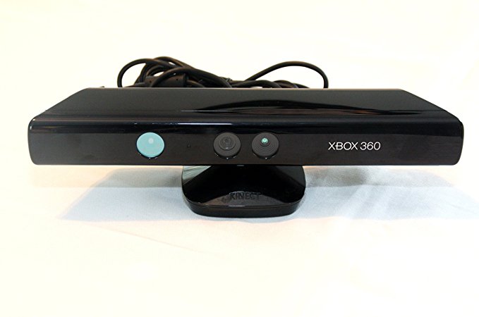
Microsoft Kinect
Kinect is Microsoft’s motion sensor add-on for the Xbox 360 gaming console. The device provides a natural user interface (NUI) that allows users to interact intuitively and without any intermediary device, such as a controller.
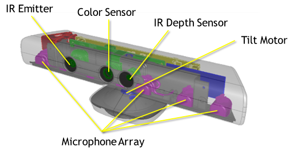
The Kinect system identifies individual players through face recognition and voice recognition. A depth camera, which “sees” in 3-D, creates a skeleton image of a player and a motion sensor detects their movements. Speech recognition software allows the system to understand spoken commands and gesture recognition enables the tracking of player movements. Although Kinect was developed for playing games, the technology has been applied to real-world applications as diverse as digital signage, virtual shopping, education, telehealth service delivery ,Robotics ,3D mapping etc
There's a trio of hardware innovations working together within the Kinect sensor:
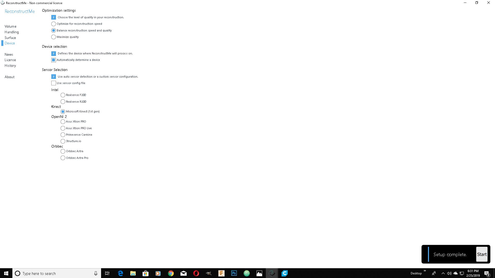
My friend Gauri volantear for 3d scanning. I have used Re-Construct Me . I started a new scan and select Kinect as input device.
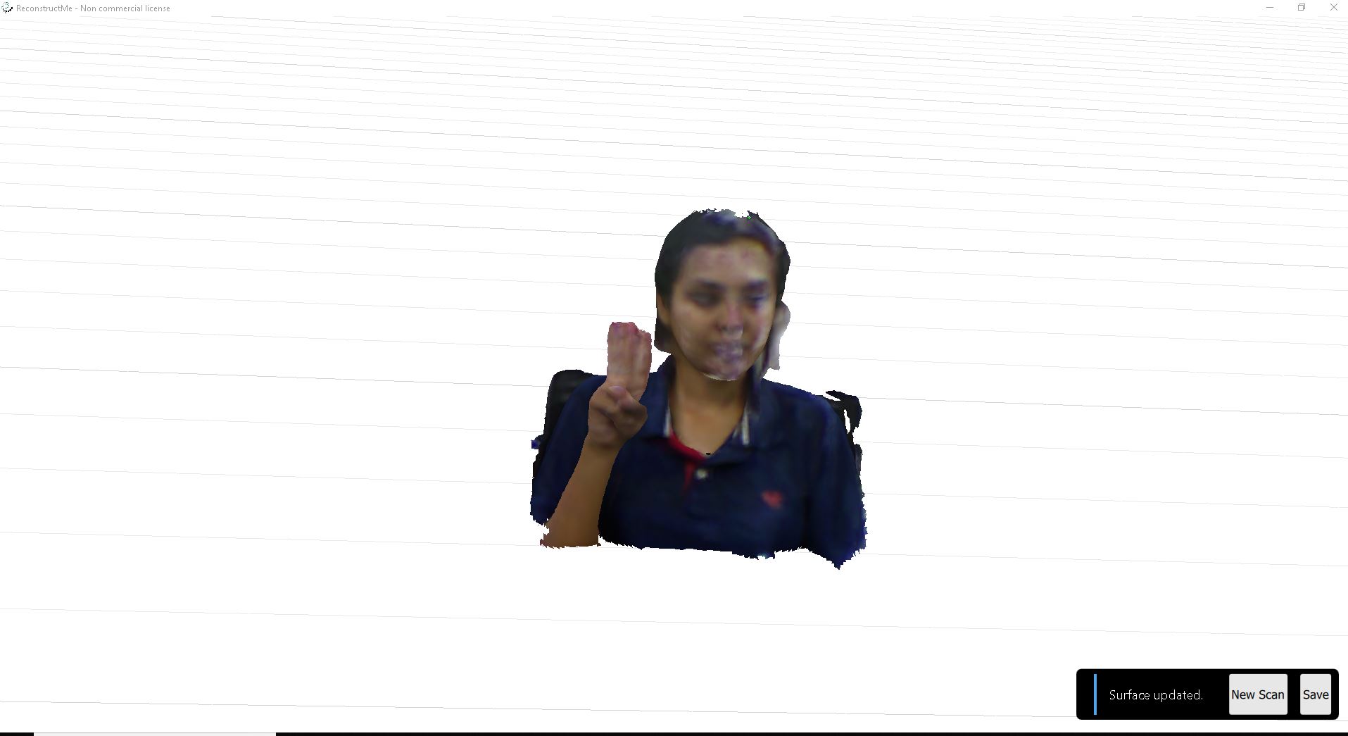
So I started my scaning and I got following result.
Now I have to save it. So I save it in my repo as an .stl file.
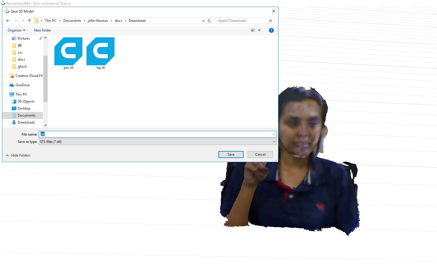
You can download the file Here
Now we have to print it out. For that we put the file into cura and export G-code
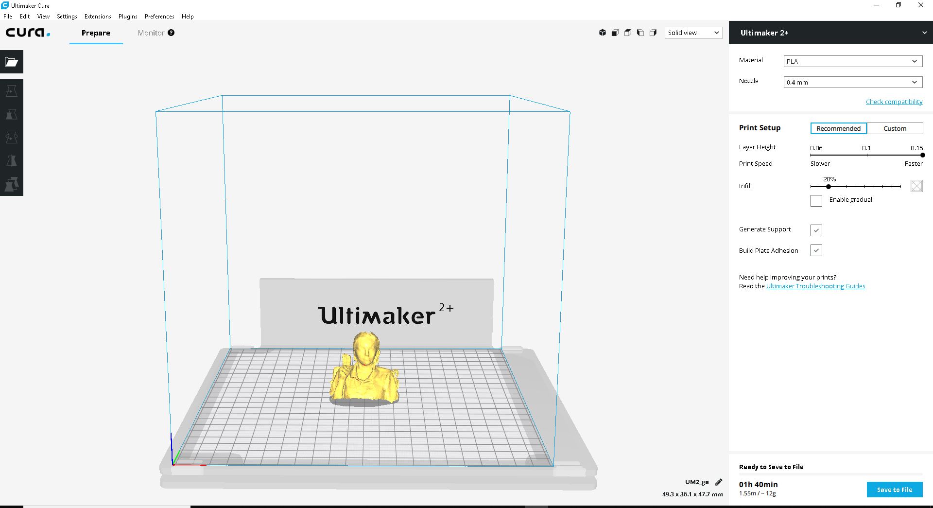
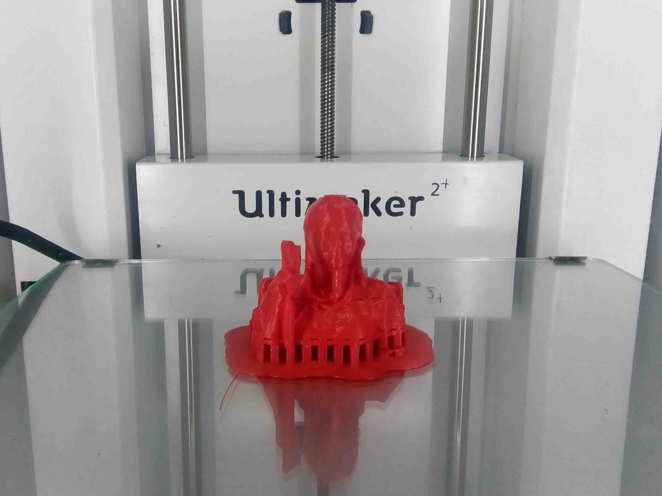
I put the Sd cart into ultimaker and start printing
When the printing is done, it looked like this.
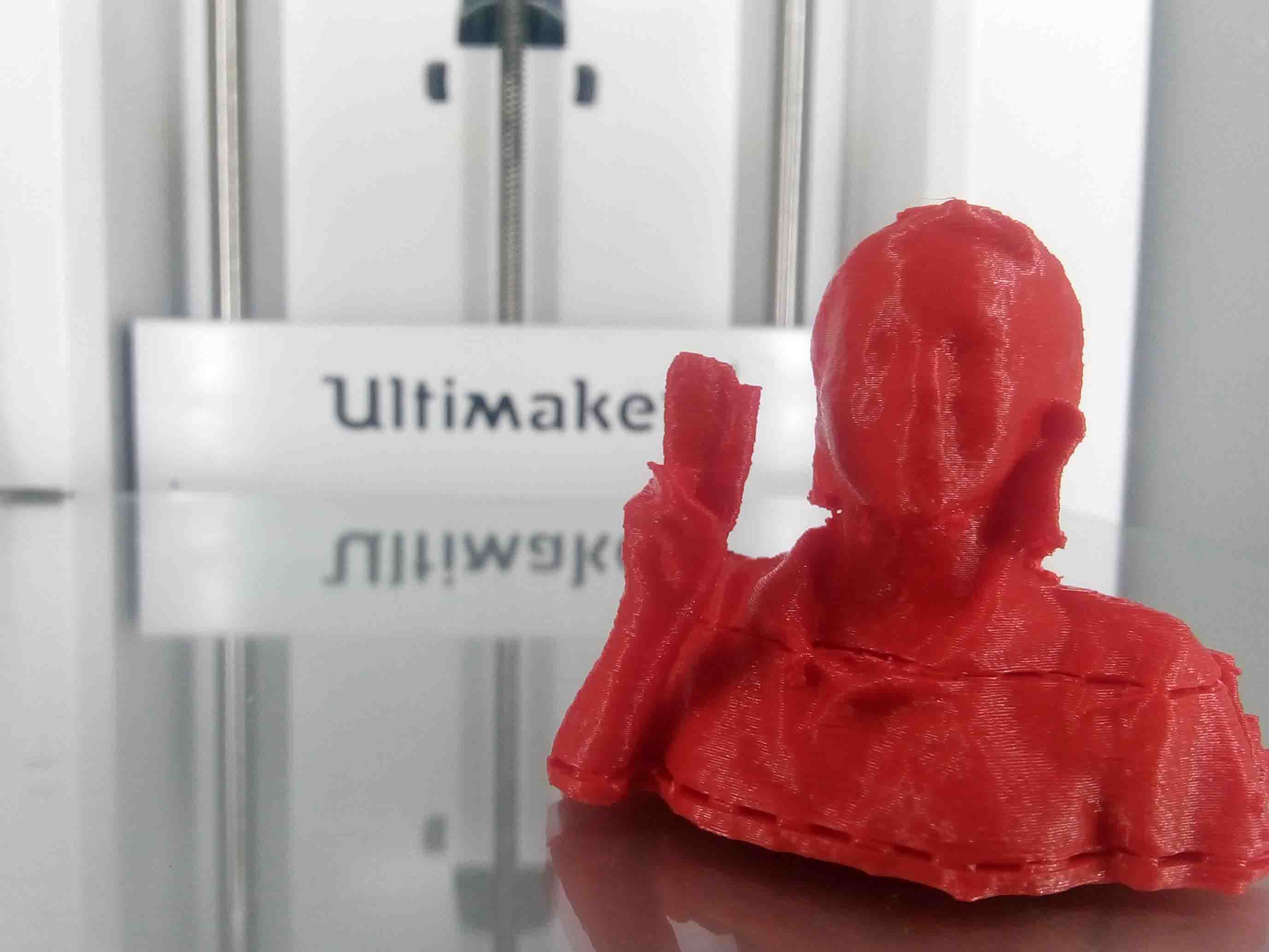
There were only few supporting materials. So cleaning up was very easy. It looked like this:
Hero Shot
You can download the file Here.