Electronics Design
So it's the 7th week and we are back with electronics again. So let's see what are the Assignments:
Introduction
So I have to redraw an electronic circuit diagram of a hello-world board. As I was from an electronic field building circuits been a part of my life for ever. But I never use the software’s such as Eagle CAD or KiCAD. So learning these software tools was the first task for me. It was a fun process. But not very easy get success in first try. So let’s meet our design tools and elements.
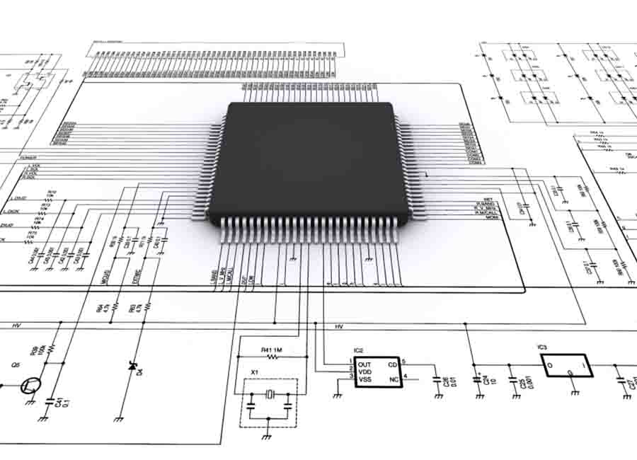
Before we go to the design part, let’s learn a bit about our circuit. hello-world board consists of a microcontroller. The microcontroller can be programmed as we wanted it to be. Here we need to operate an LED and a button switch. For that we need to check it's parameters. I got datasheet for online sites like digikey. Even it's a fun process, the path to sucess is bitter in this case.
Designing
Using a breadboard and some jumper wire was the easiest way to make a circuit. But the connections are temporary. Also the number and size of the componets will increase in this case. So I am using a PCB to make the circuit. PCB is more durable and a permanent solution against breadboard. So we are using following softwares to make design:
Now learn some basics...
Basic Electronics
Pull-Up/Down resistors
Pull-up resistors are used in electronic logic circuits to ensure that inputs to the arduino settle at expected logic levels if external devices are disconnected or high-impedance. 'Just because you have nothing at all connected to an input pin doesn't mean it is a logical zero.'

A pull-up resistor weakly "pulls" the voltage of the wire it is connected to towards its voltage source level when the other components on the line are inactive. When the switch on the line is open, it is high-impedance and acts like it is disconnected. Since the other components act as though they are disconnected, the circuit acts as though it is disconnected, and the pull-up resistor brings the wire up to the high logic level. When another component on the line goes active, it will override the high logic level set by the pull-up resistor. The pull-up resistor assures that the wire is at a defined logic level even if no active devices are connected to it.
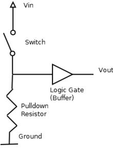
A pull-down resistor works in the same way but is connected to ground. It holds the logic signal near zero volts when no other active device is connected.The value of a pull down or pull up resistor will vary depending upon your specific devices involved.
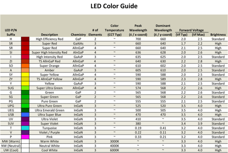
LED series Resistor value
A light-emitting diode (LED) is a two-lead semiconductor light source. It is a p–n junction diode that emits light when activated.If we apply a current that is greater than the desired value of an led the junction temperature will increace because Heat = I^2 x R x t ,(I = current through Led,R = Resistance of conductor,t = time ) .So if the junction temperature increas it may lead to the fast deterioration of the juction or complete breakdown of the device so it is importent to maintain the current through the led . the easiest and simplest way is to use a series resistor.
So let's take an example
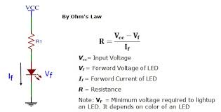
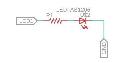
The above figure is a typical led connection where .Rs is the Series resistance ,Vs is the source voltage,Vf is the forward voltage of the LED(also referred to as the "voltage drop") ,If is the safe current through the LED
So we have
Vcc = supply voltage =5v
Vf = 1.8V
If = 18mA
So R = (5 - 1.8)/(.018) = 177.77
The closest resistor having a greator value than this in our lab is 499 ohm . I hope may be this work with a reduced brightnes.
Eagle
EAGLE is a scriptable electronic design automation (EDA) application with schematic capture, printed circuit board (PCB) layout, auto-router and computer-aided manufacturing (CAM) features. EAGLE stands for Easily Applicable Graphical Layout Editor.EAGLE contains a schematic editor, for designing circuit diagrams. Schematics are stored in files with .SCH extension, parts are defined in device libraries with .LBR extension. Parts can be placed on many sheets and connected together through ports.The PCB layout editor stores board files with the extension .BRD. It allows back-annotation to the schematic and auto-routing to automatically connect traces based on the connections defined in the schematic.
EAGLE saves Gerber and PostScript layout files as well as Excellon and Sieb & Meyer drill files. These are standard file formats accepted by PCB fabrication companies, but given EAGLE's typical user base of small design firms and hobbyists, many PCB fabricators and assembly shops also accept EAGLE board files (with extension .BRD) directly to export optimized production files and pick-and-place data themselves.

Schematics
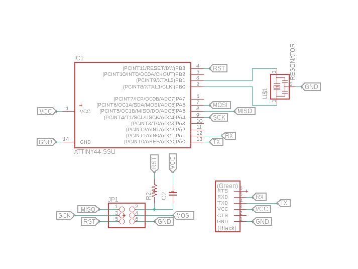
So the assignment was to redraw the echo-hello-world circuit for that we need to create a design in Eagle. For that first I install Eagle and opended it on desktop.
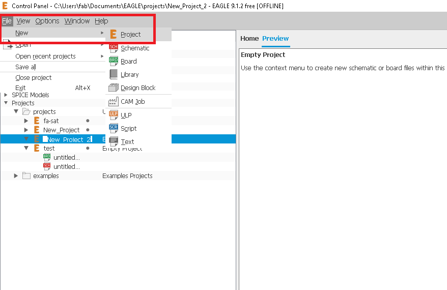
Next go to "File" and enter "Project"
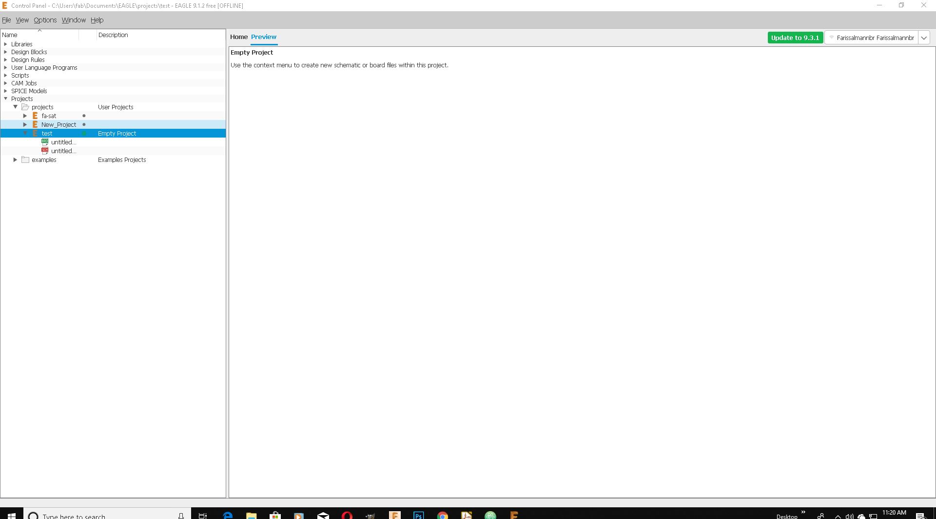
Now I got an empty project
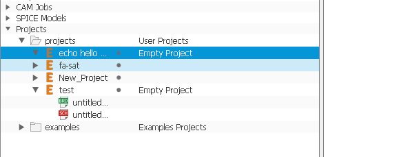
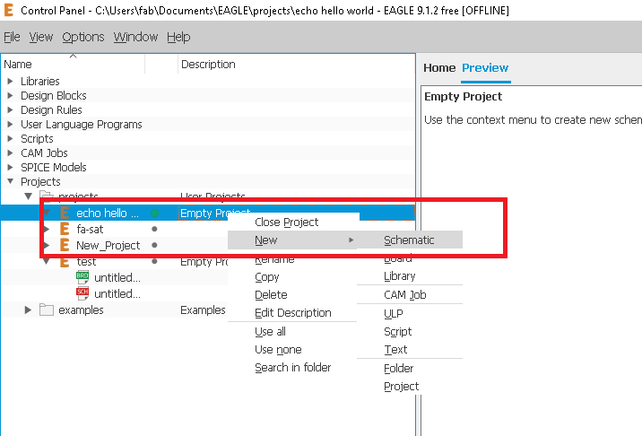
Now right click and "Rename" it. Also press "Schematics" to open a new schematic.
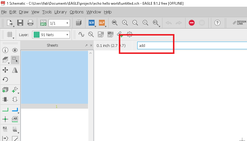
Now I have to design a circuit diagram. For that I must add some components. Type "Add" in command
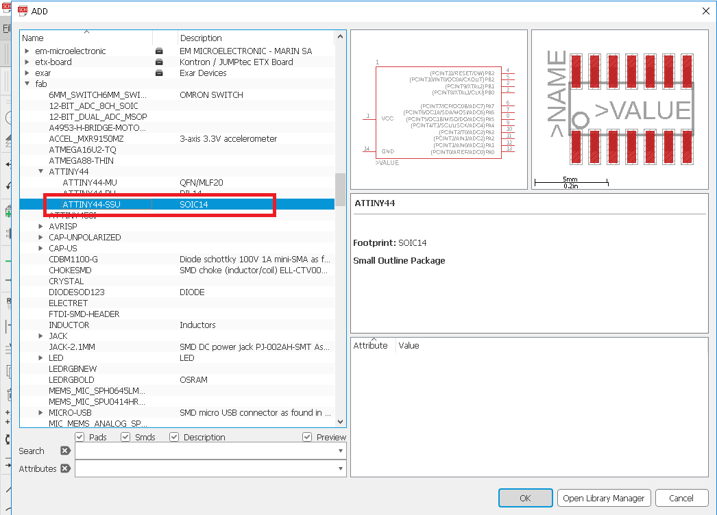
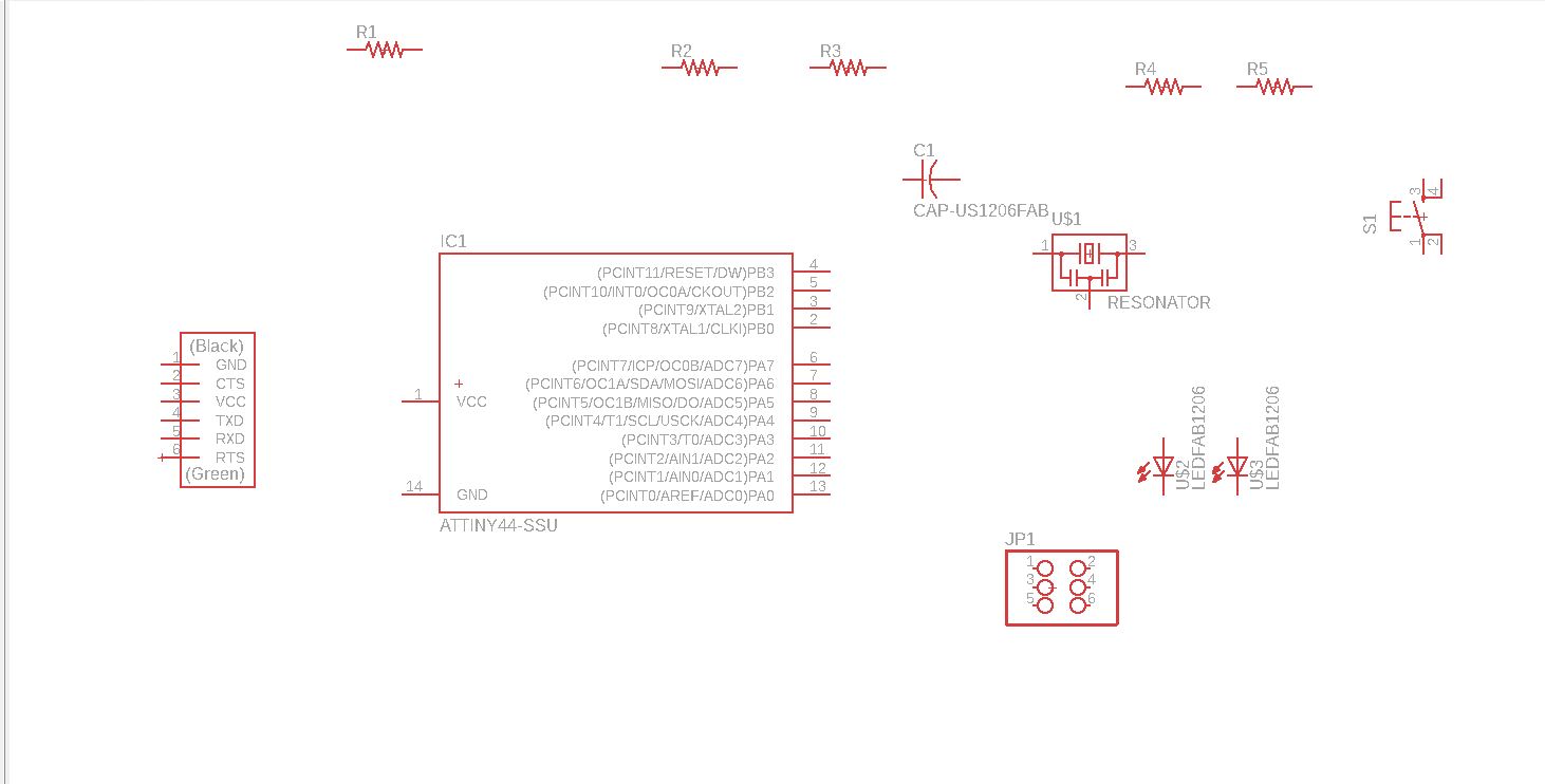
I previously installed Fab libraries to Eagle. So I got all the components I need for it under fab option in Add panel. I select each component I need and press "Ok"
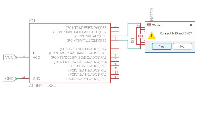
Now I got all the components I need to connect each to together.For that I used "Net"
I also use "Label" option to minimize visible connection.
When I am done It look like this
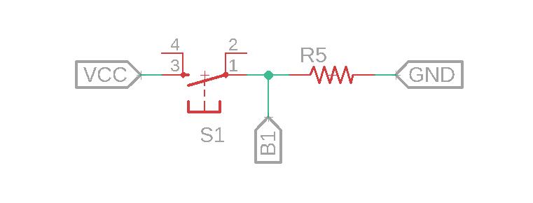
Now I had to add push-button and LED so I add both of them to circuit
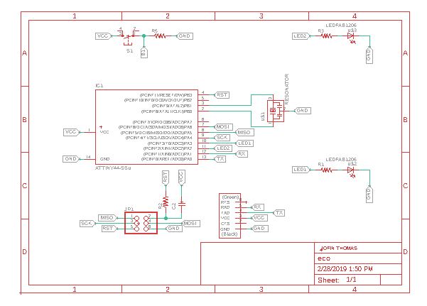
Now add frame and circuit is done.
Now lets start on Board design. Push "Switch to board"
Board
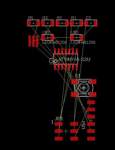
Now I open Board design. Drag it to the center
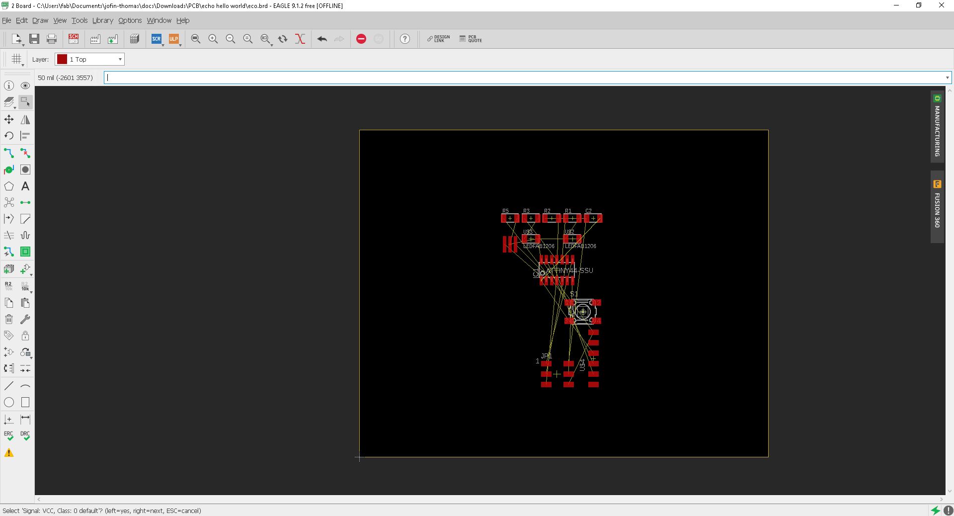
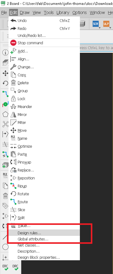
Now we have to set rhe design ruples for modella MDX200. For that I open "Design rules" under "Edit"
Design Rules
First open desn rules
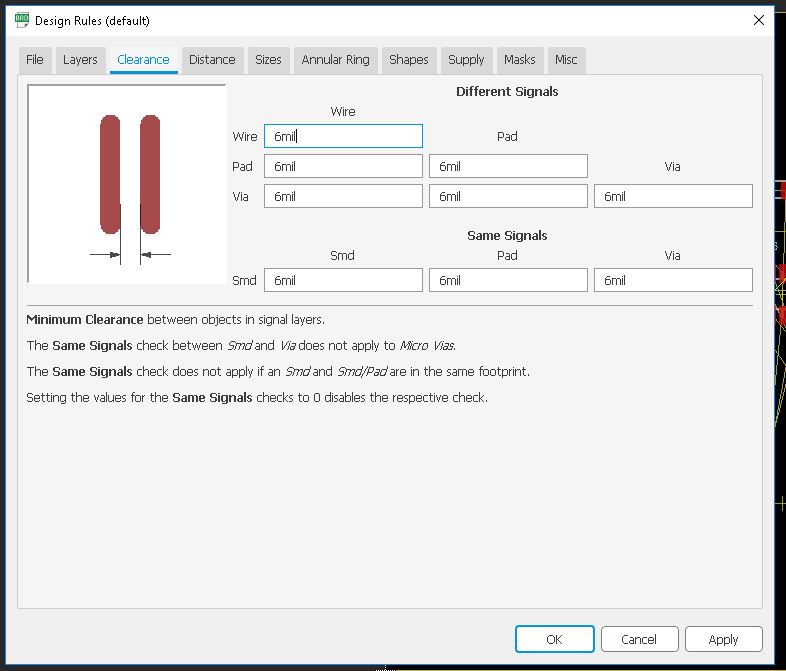
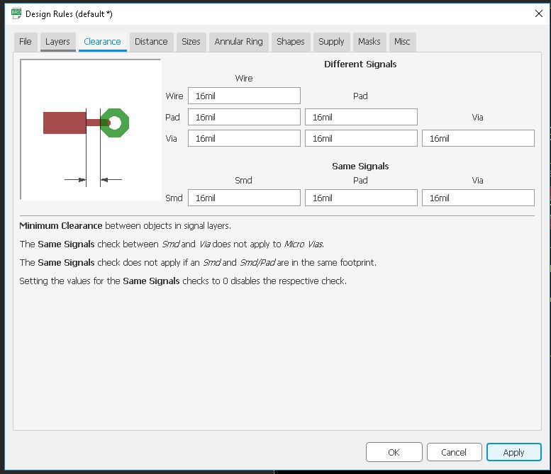
First we need to set the Clearnce , in default it' comes with the 6 mil in here fab we are using 1/64 bit for milling so here the trace will come around 16 mill.
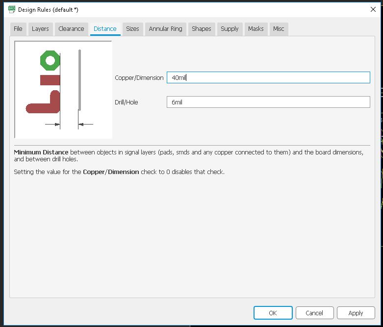
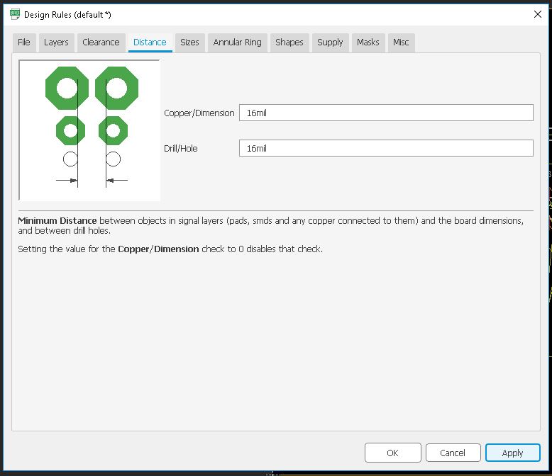
Next we need to take care the Distance ,it default value is 40 mil so in here i set the value to corresponding to our bit that is 16 mil.
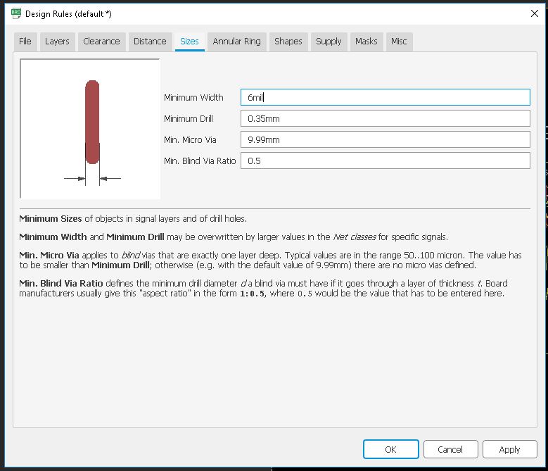
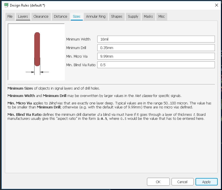
Next we need to set the Size of the Copper Trace , in dafult 6mil, and we need to make it 16 mil.
Now press "Ok".I also used the ERC- Electronic rule checker
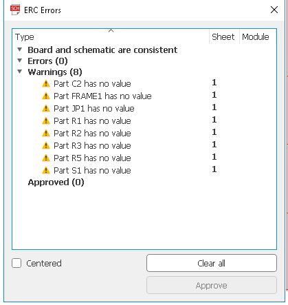
in here we can see , there is no error in my design , but have few warnnings , that's due to i did't give the proper value to componets.this is not big deal if the footprint is same. we can approve all now.
So now set the all the design rules we need to create the PCB board using the Modela Milling machine.
Setting up PCB
We need to place the componets to place
I used "Auto-router" to Route my PCB Trace Line
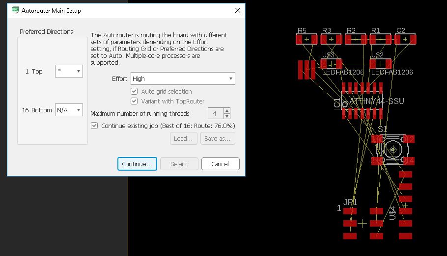
In default it's comes with Bottom and Top layer , but here we are using One layer so used Top layer only.
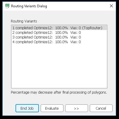
Auto-route will suggest so many routes , we can choose one that's suitable us.
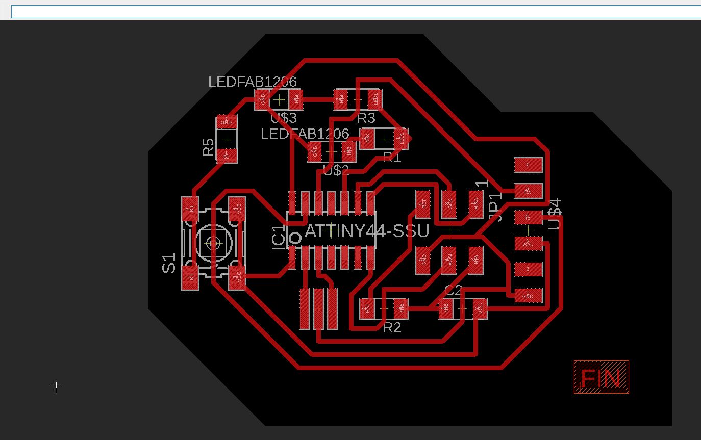
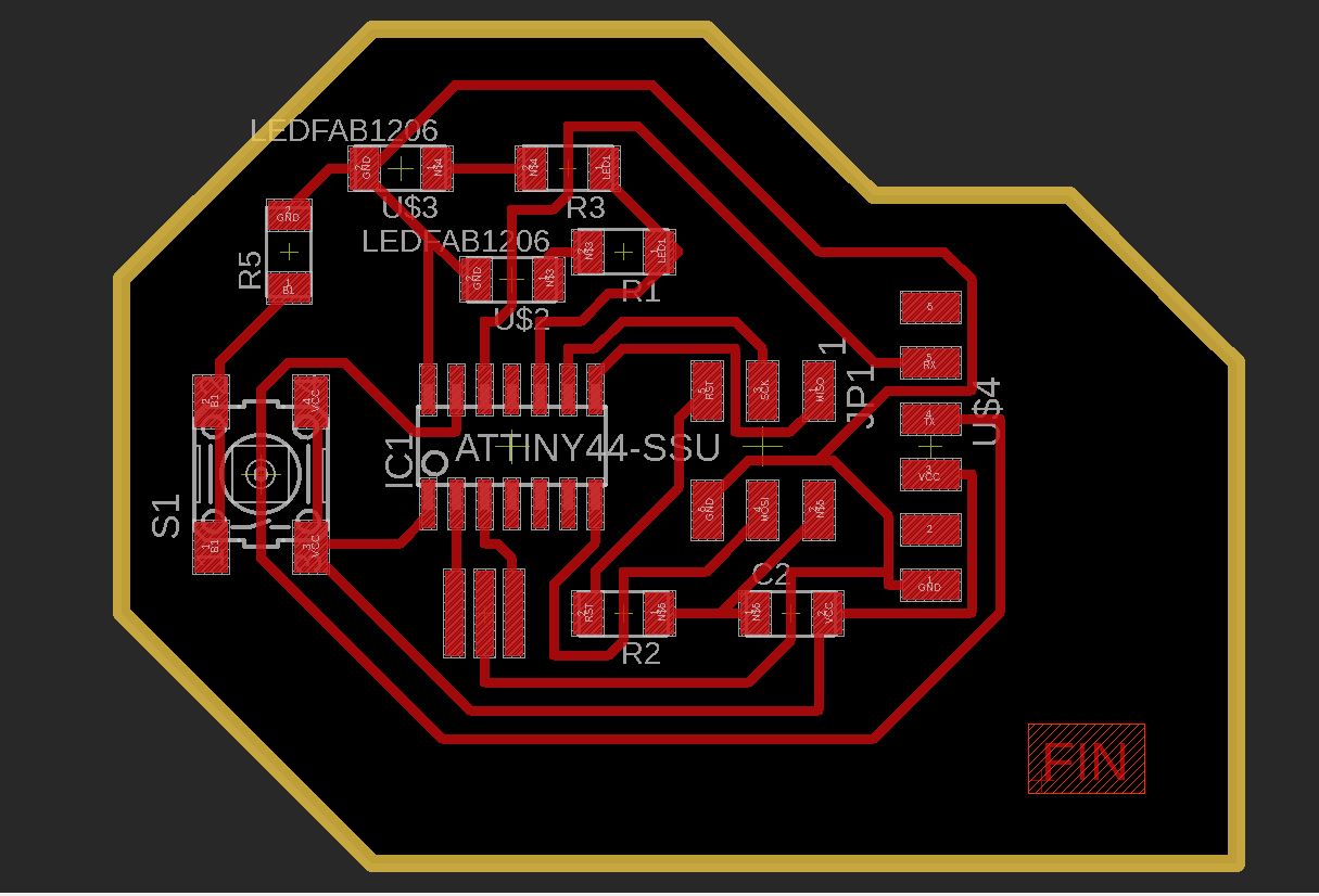
I used the first 100% Routed one. I added an optimized border to it after that
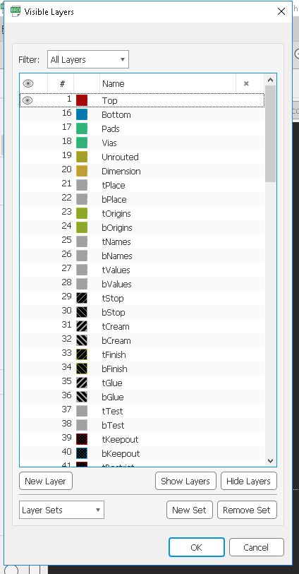
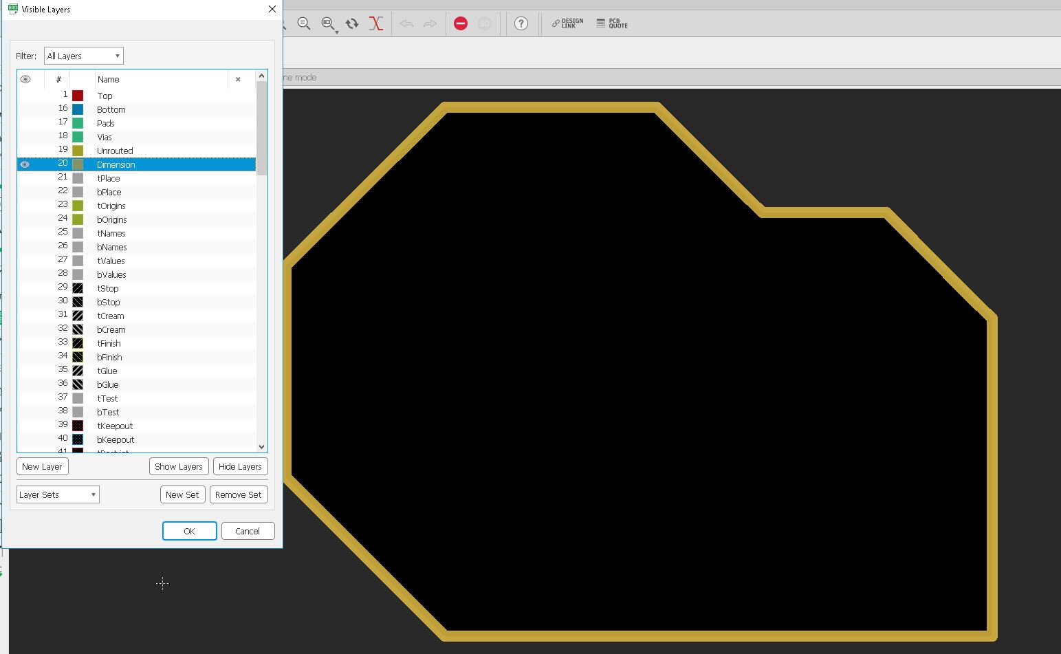
Now we need to export the mill trace and cut trace in .png format. For that we have to hide some layers. Go to layers and click "Hide all layers".Also select "Top layer" to export
Now go to "File" and click "Export"
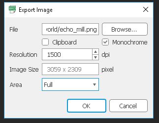
Make sure to hit Monochrome and set resolution to 1500. Now repeat the same with cut line also
Ater that export it to .png
Milling and Soldering
I explaind about the PCB milling procedure in the Week5 :- Electronics Production . same as here , am using Modela MDX for milling the PCB.
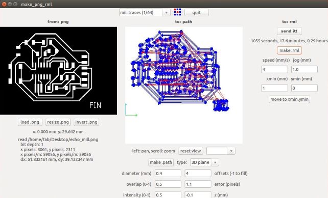
I used the Fab Modules with Modela to mill PCB.for milling i used 1/64 bit.
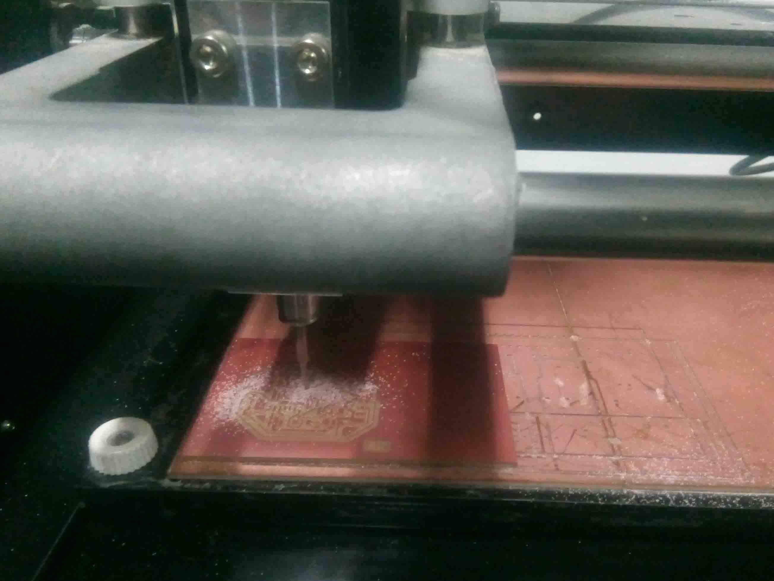
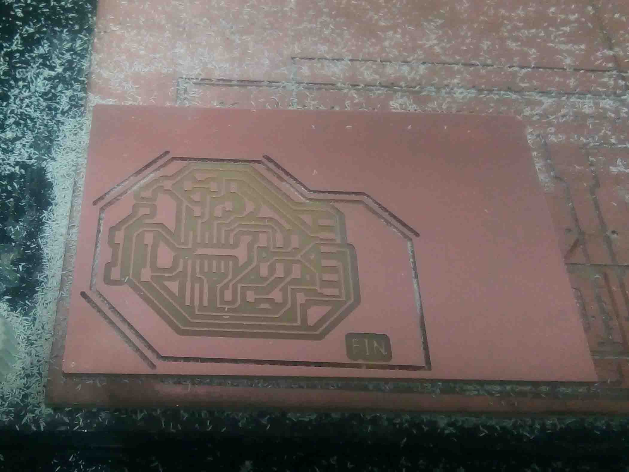
I started milling. After milling ended I change the bit for cutting and load png in fab module
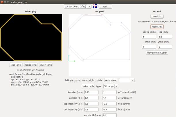
For cutting the trace I used 1/32 bit. Afer cutting it looked like this
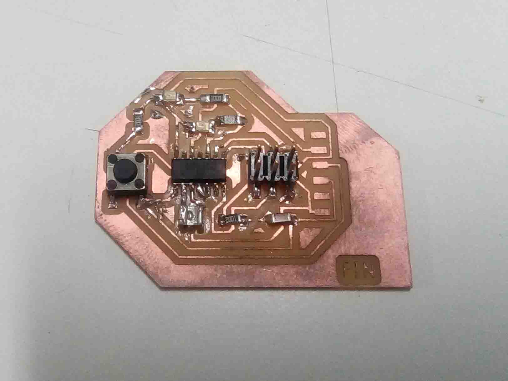
Now we need to solder it. For that first I collected the components from inventory and solder it like we I did it in the week 5
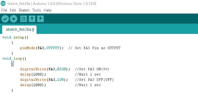
Now I need to program it. For that I opened "Arduino IDE" and entered below code
                              int led = PA3;

                               void setup()

                                {

                                  pinMode(led,OUTPUT);

                                }

                                void loop()

                                 {

                                   digitalWrite(led,HIGH);

                                    delay(1000);

                                    digitalWrite(led,LOW);

                                     delay(1000);

                                   }
There was a mistake in my circuit diagram. I for got to add a "Reset" wire to reset pin. So board didnt work. I had to add some adjustment to the board in order it to work. My instructor help me to figure out the mistake when I am unable to do it. I added some wires and eliminate some paths
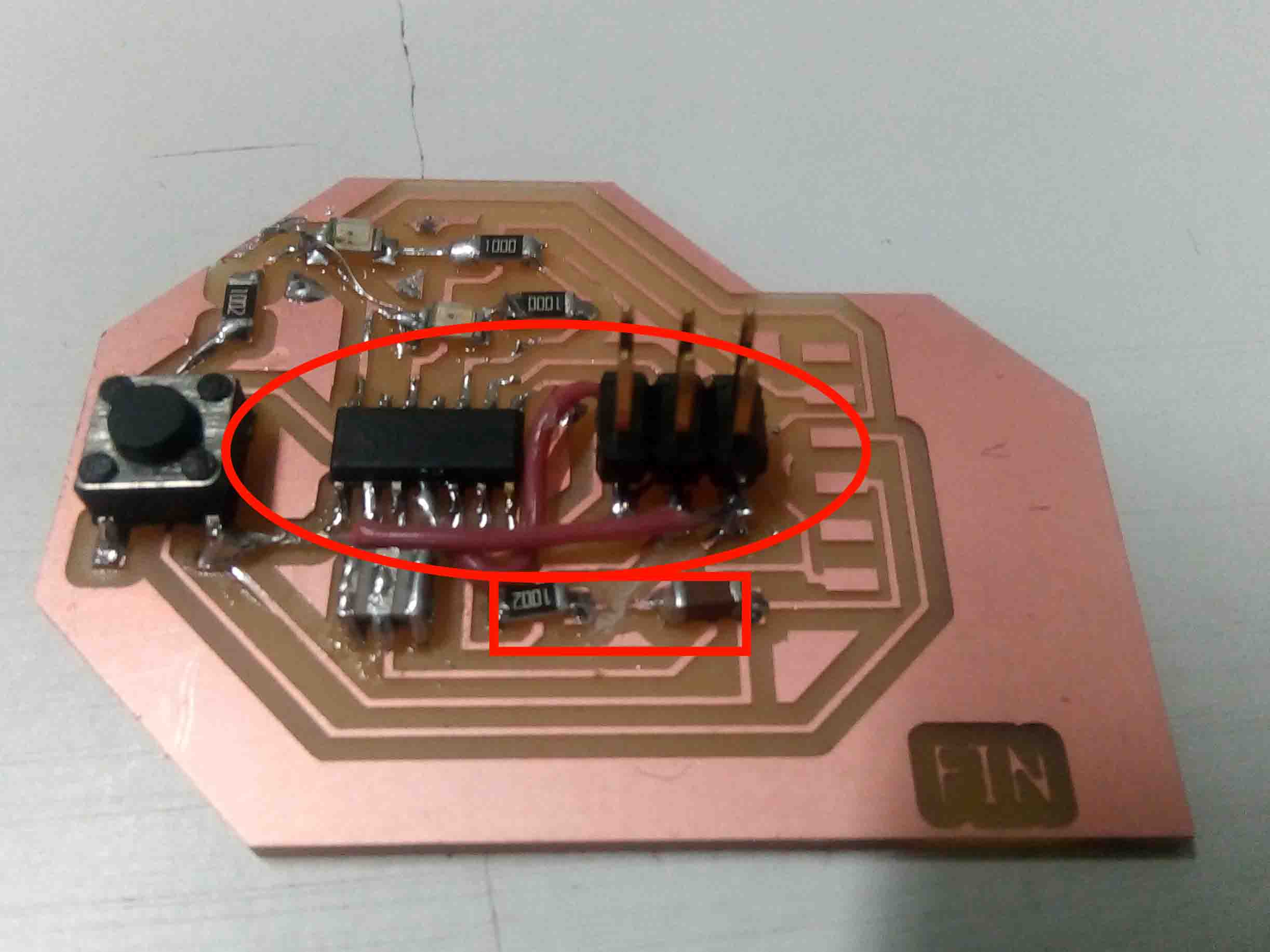
After some repairs it worked perfectly
The button didn't connect with the attiny 44. So I designed an other circuit solving all the problem and it was a sucess.
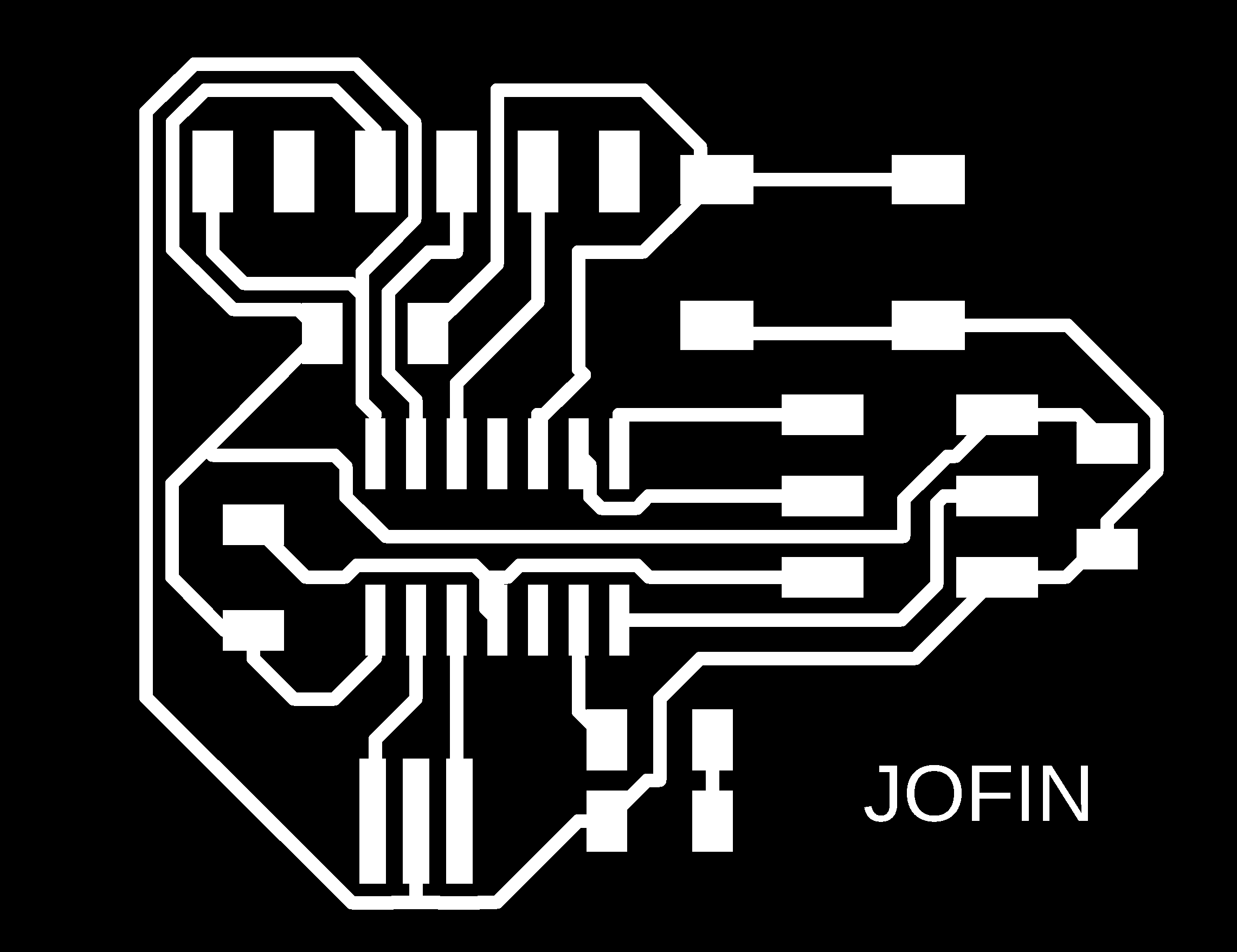
Trace and Cut image
Trace
Cut Image
So I need to repeat the whole process again from milling to soldering.
Milling
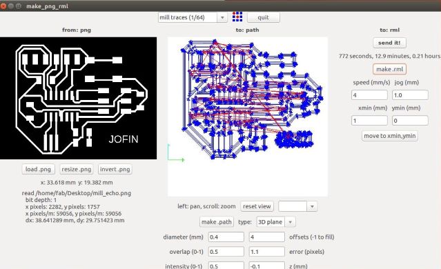
I used the Fab Modules with Modela to mill PCB.for milling i used 1/64 bit.
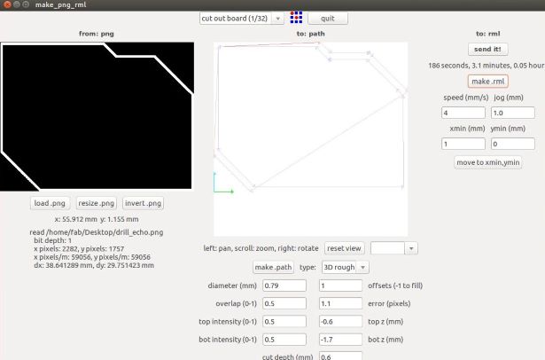
For cutting the trace I used 1/32 bit.
Soldering and programming
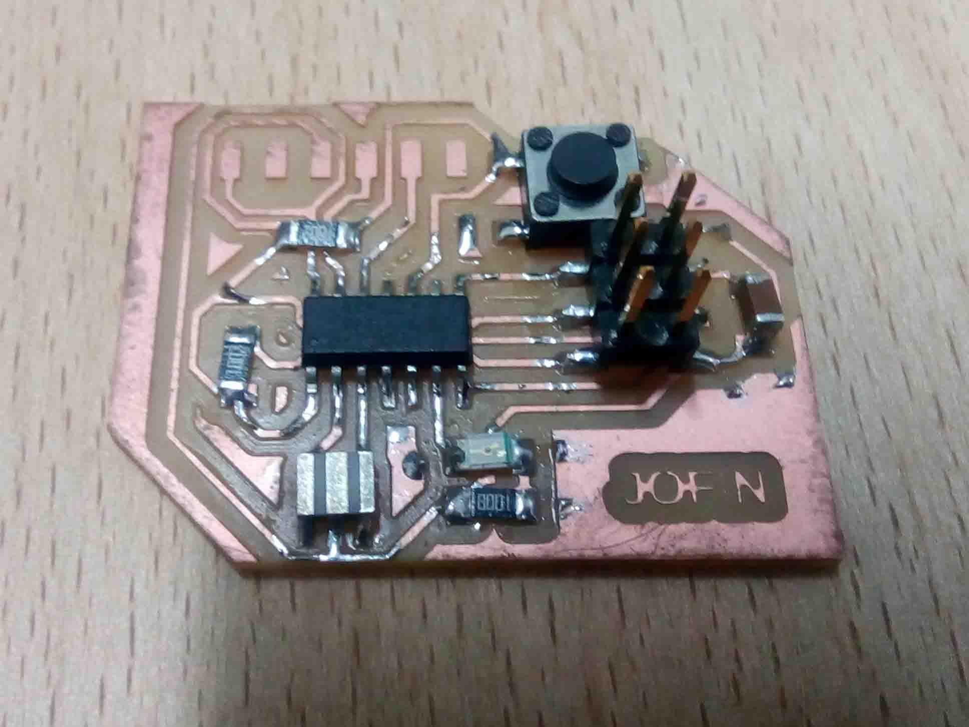
After soldering, it lloked alike above. Now I need to program it. The circuit is quite different from previous one. So program I prepared for the previous one will not work for this one. So need to correct the code for this one.
Arduino Code
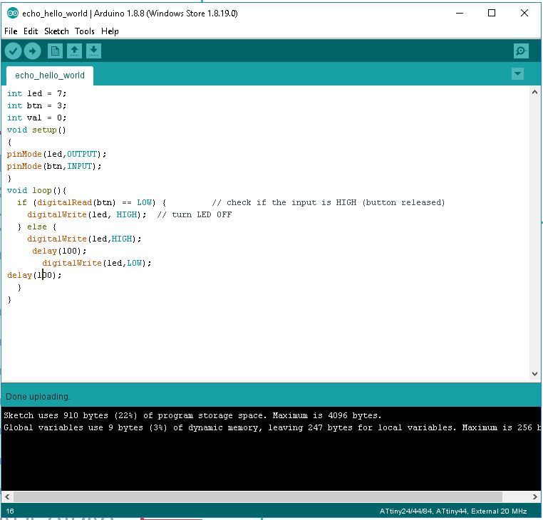
Here is the code that I used for the board;
int led = 7;int btn = 3;
int val = 0;
void setup()
{
pinMode(led,OUTPUT);
pinMode(btn,INPUT);
}
void loop(){
if (digitalRead(btn) == LOW) { // check if the input is HIGH (button released)
digitalWrite(led, HIGH); // turn LED On
} else {
digitalWrite(led,HIGH);
delay(100);
digitalWrite(led,LOW);
delay(100);
}
}
This time it was a success
Normal
Push-Button
So that's it for the individual assignment. So let's see what is the group assignment we have...
Group Assignment
This week's assignment was to use the test equipment in your lab to observe the operation. So let's meet with the electronics equipments
Multimeter
A multimeter is a tool for testing different parameters of an electronic circuit board.In our lab, we use UNI-T UT61A multimeter. You can download the user's manual from Here
Tests can be done using Multimeter
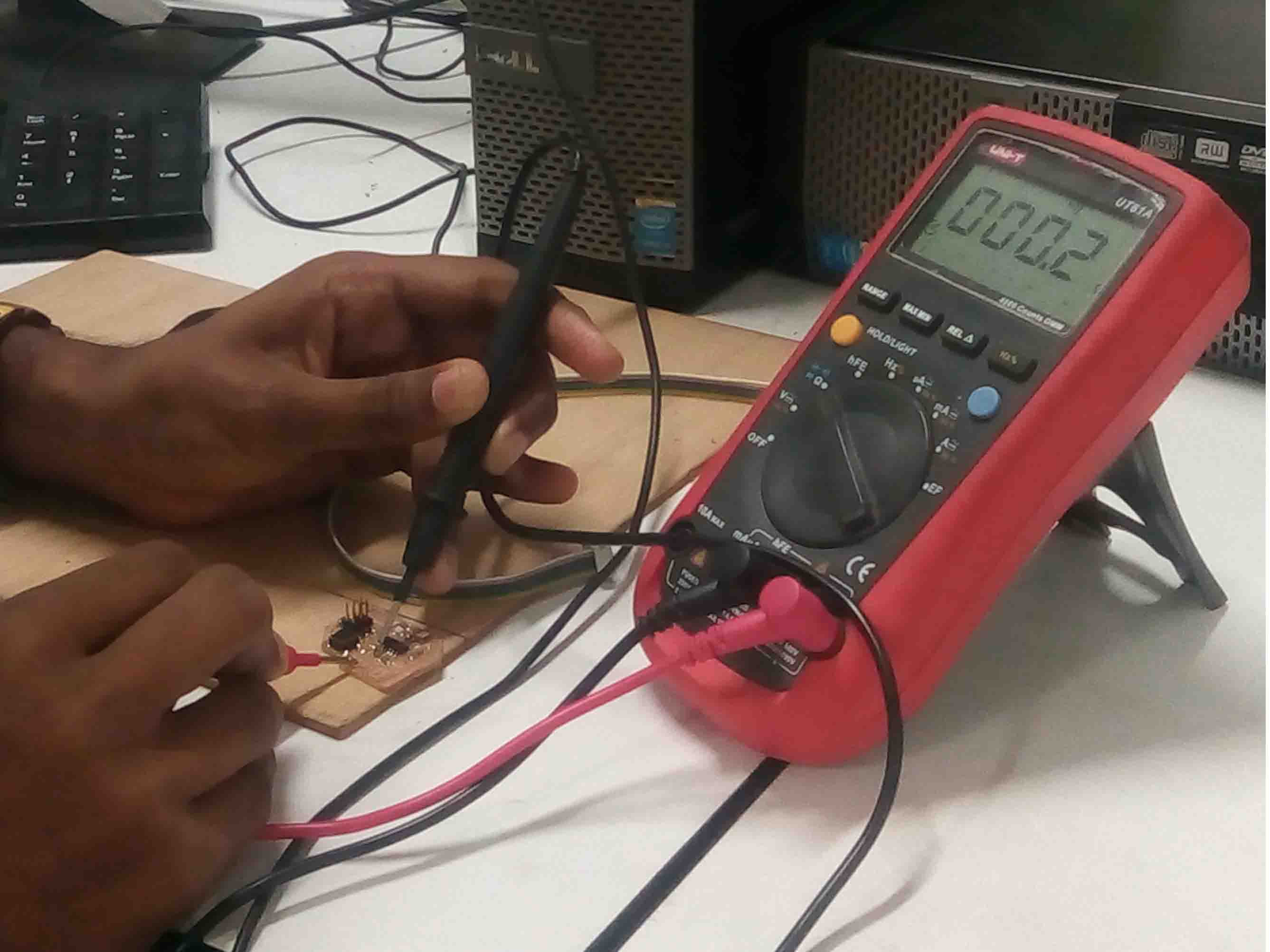
I used multimeter for testing continuity in my PCB
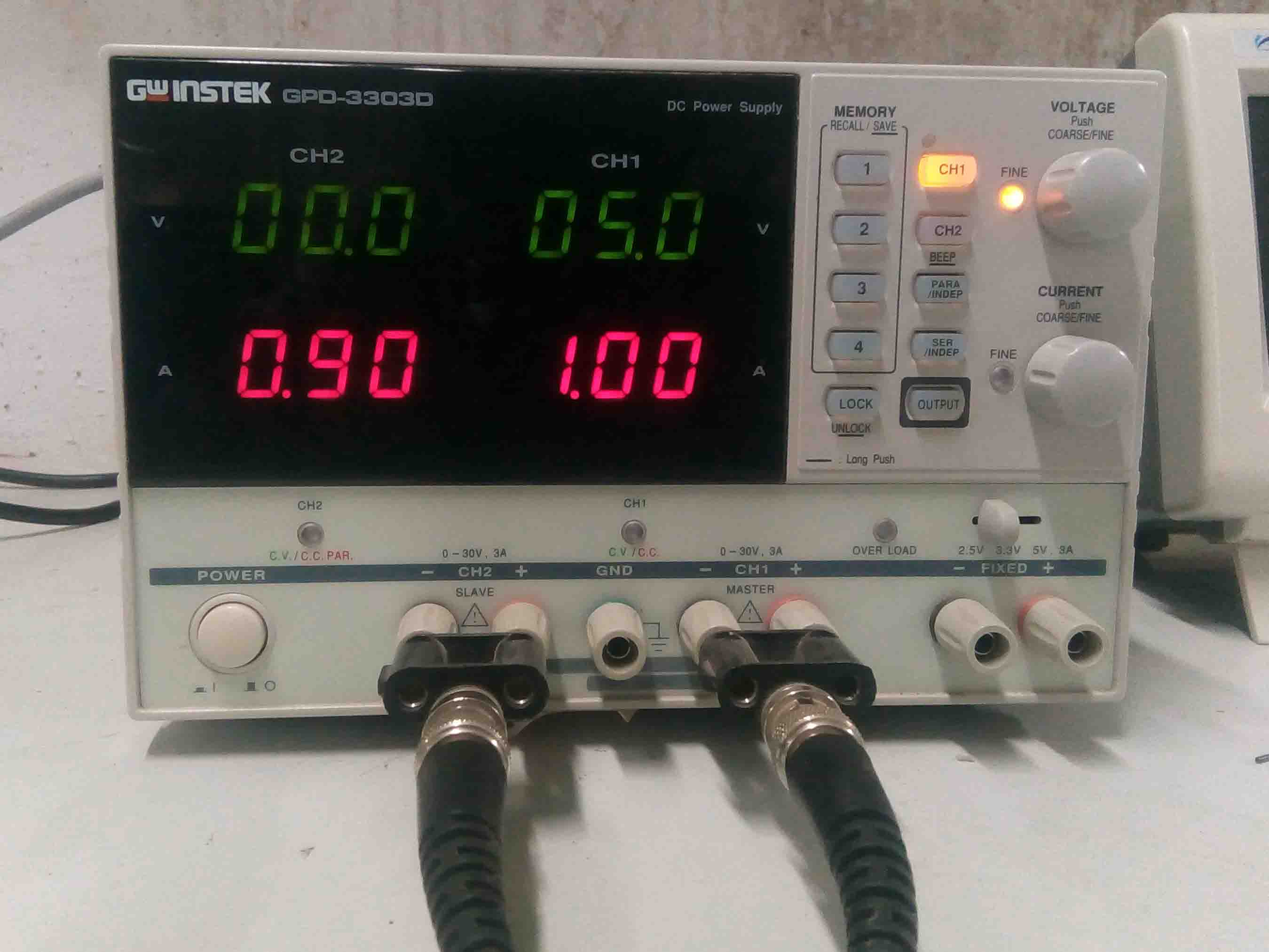
DC Power Supply
In falab kochi we use Gw instek GPD-3303D. You can download the user's manual Here
Features
Digital Oscilloscope
In falab kochi we use UNI DSO-1100. You can download the datasheet Here
Features
Function Generator
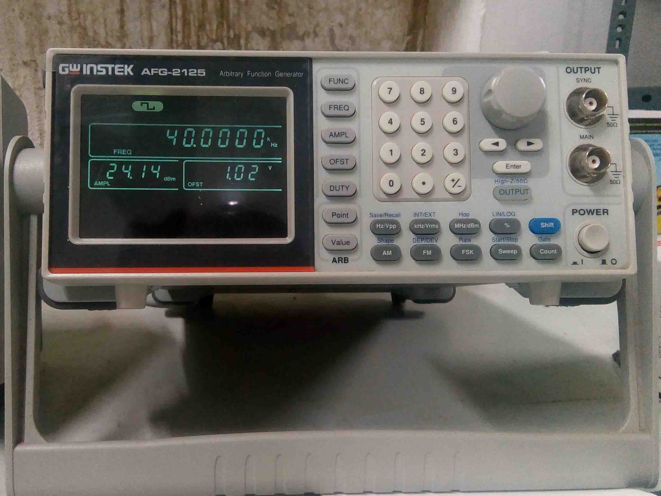
In falab kochi we use GW Instek AFG-2125 . You can download the datasheet Here