Electronic Production
So it's the 5th week since I begin my fab journey. In this week, I got following assignments,
So we are going to make an ISP. I have used ISP's before and I am well trained in soldering and electronics field. So this week's assignment was not that complcated to understand. But I have never usd a CNC mill to fabricate a PCB. So let's begin with that.....
Modella MDX 20
The Roland Modela MDX-20 is a small milling machine and a 2 1/2D precision scanner.This machine is mostly used for milling circuit boards, though it can also mill in other soft materials like machinable wax. For milling circuit boards you should export you design into a black&white monocroome png. For milling out 3 dimensional molds you should export your design as .stl. The second use of this machine is scanning. It uses a thin needle to gently touch the object and calculates from this a 2 and a half dimensional model. Though slow at processing, it can create a high detailed model.
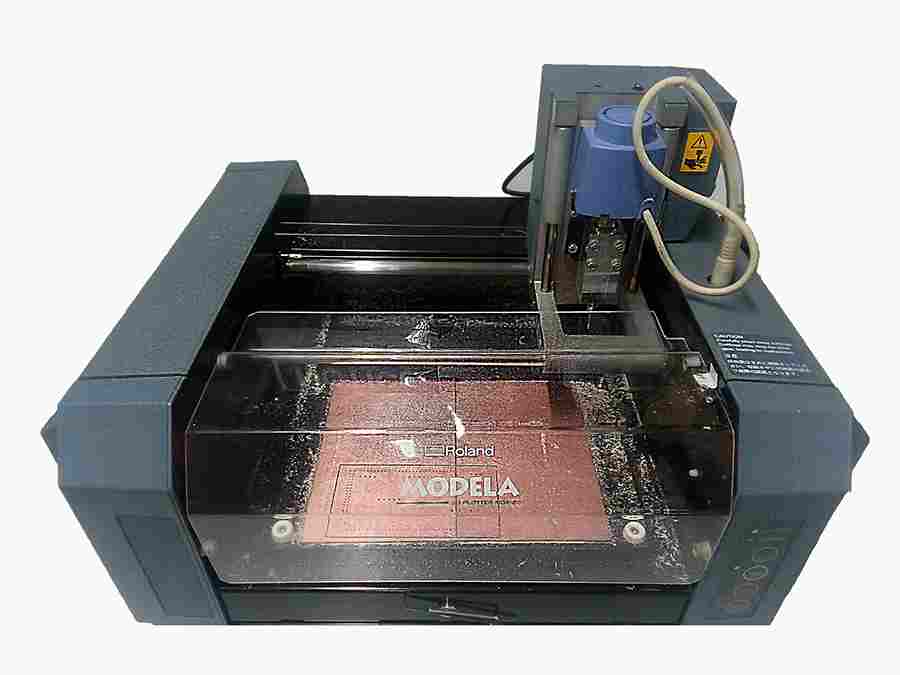
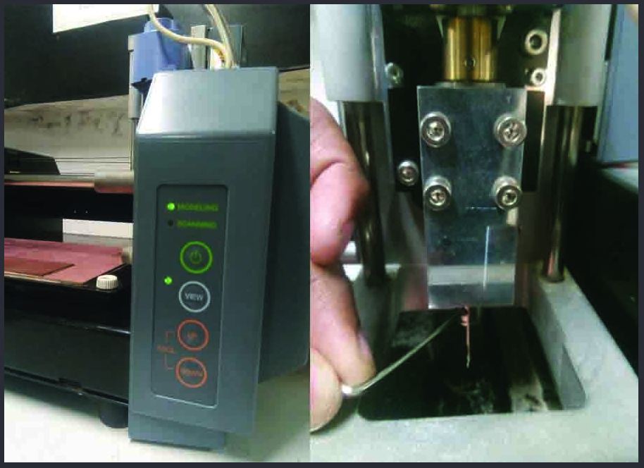
So lets meet it's parts
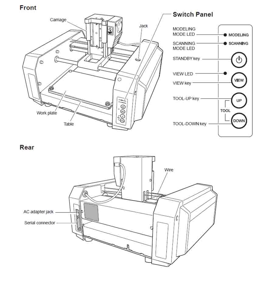
We use CNC mill for making PCB boards. You can download the User's manual Here >
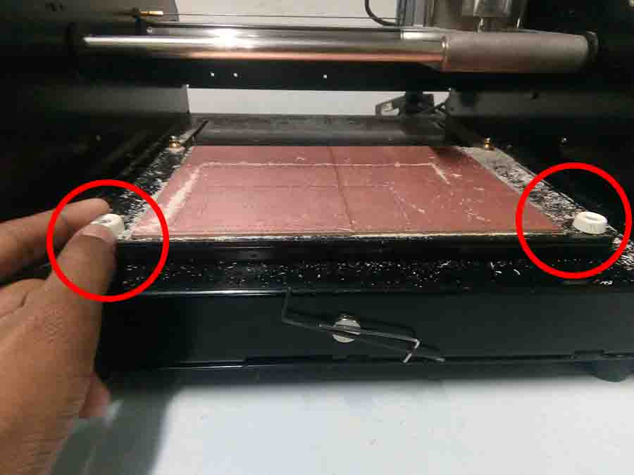
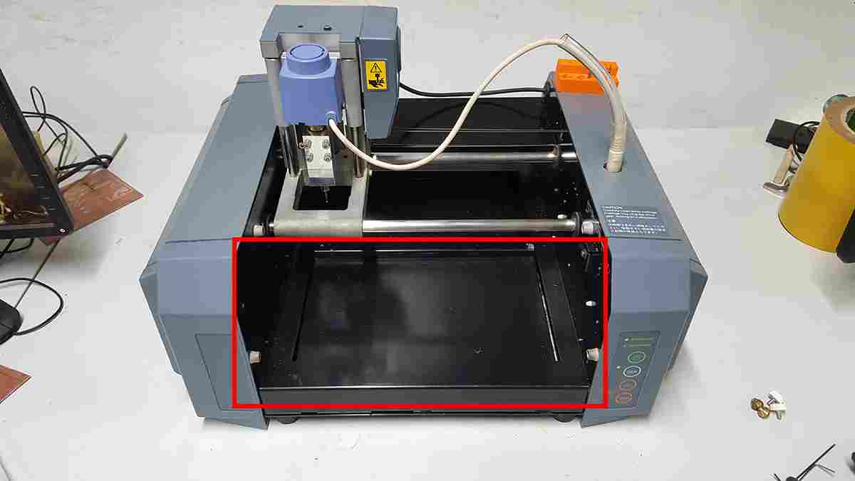
Preparing CNC
Before we start to mill PCB, we need to check whether the bed and sacrificial layers are up for the job. It might take more damage from previous works.
For fixing it, follow these steps..
Before that, let's find out that what we are making this week...
In System Programming
In-system programming (ISP), also called In-Circuit Serial Programming (ICSP), is the ability of some programmable logic devices, microcontrollers, and other embedded devices to be programmed while installed in a complete system, rather than requiring the chip to be programmed prior to installing it into the system.-wiki
FabISP is an in-system programmer for AVR microcontrollers. There are different versions of ISP's available in the archieve. I selected Brians Version of Fab ISP called "FabTinyISP".
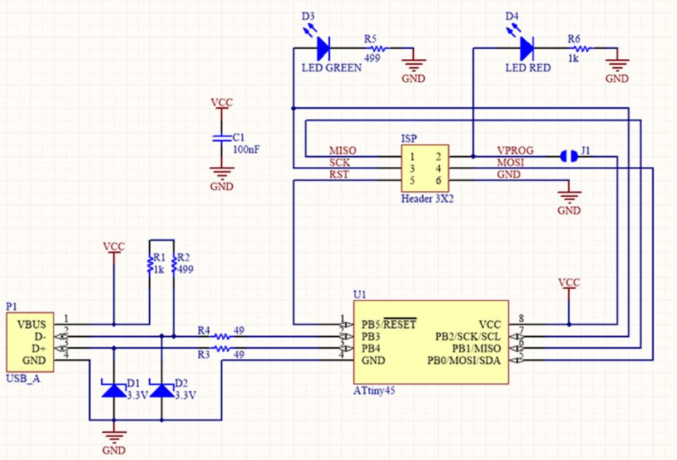
FabTinyISp
It is a ATtiny45 based board having high-performance, low-power Atmel 8-bit AVR RISC-based microcontroller combines 4KB ISP flash memory, 256-Byte EEPROM, 256B SRAM, 6 general purpose I/O lines, 32 general purpose working registers, one 8-bit timer/counter with compare modes, one 8-bit high speed timer/counter, USI, internal and external Interrupts, 4-channel 10-bit A/D converter, programmable watchdog timer with internal oscillator, three software selectable power saving modes, and debugWIRE for on-chip debugging. The device achieves a throughput of 20 MIPS at 20 MHz and operates between 2.7 - 5.5 volts.I choose Brian's verson because this design doesn't have any clock circuits and additional LED's are there to indicating the status of the board while programming.
Schematic
Position Diagram
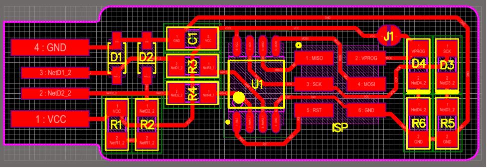
Layout
Milling Traces
Download file here
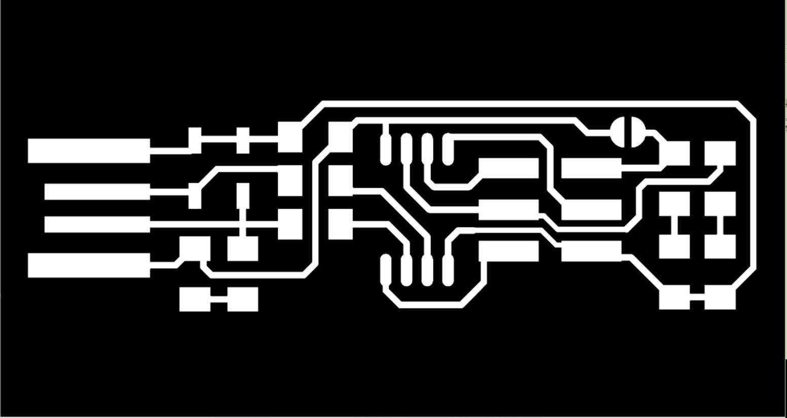
Download file here

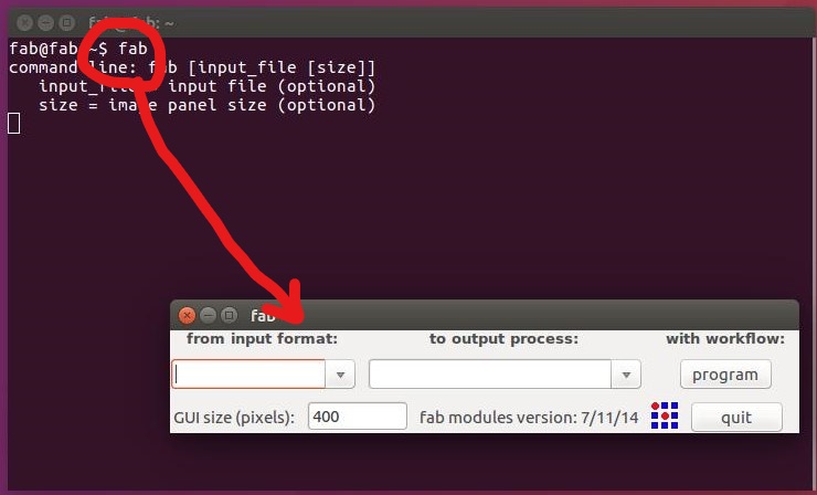
Setting up the fab modules
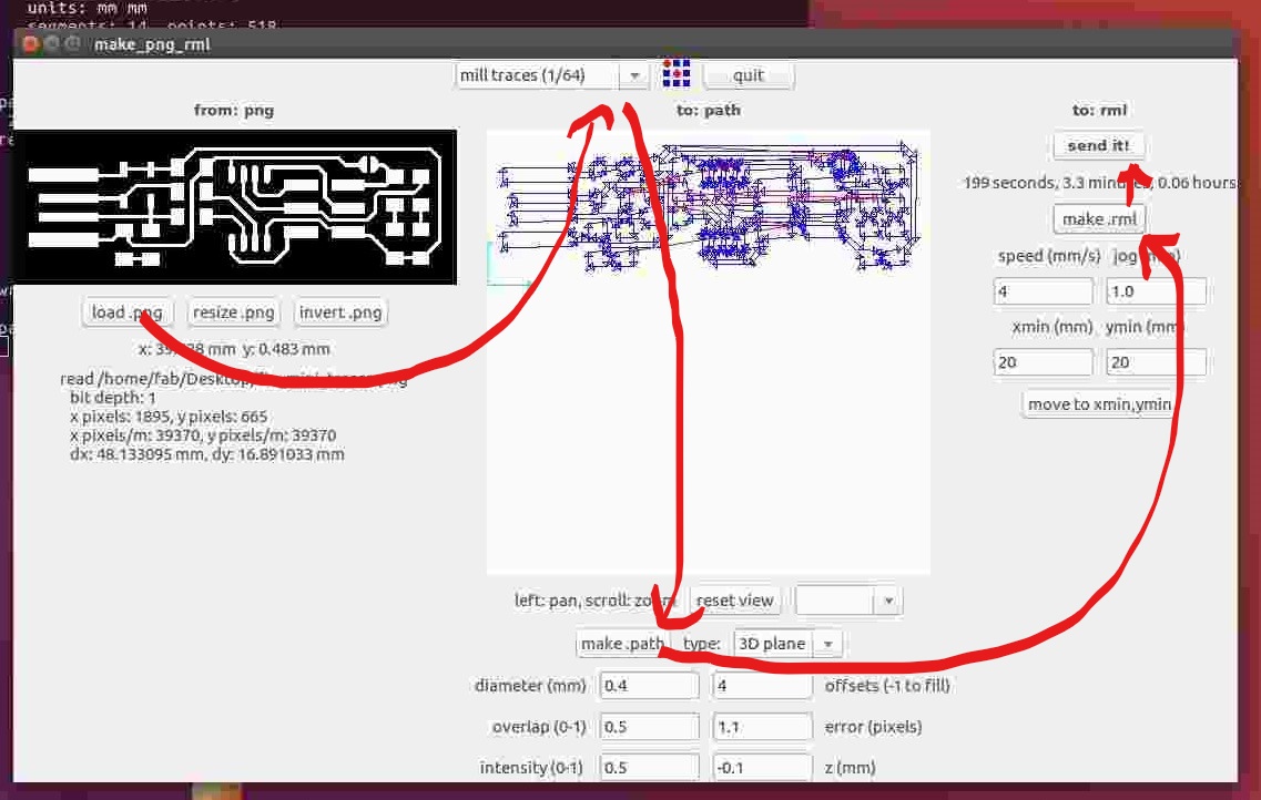
To make the PCB, first we have to setup the fab modules. For that we have to open fab modules in the computer in order to convert the png image into G-code. For that go to the terminal and run fab Now the fab module will open and the select the input format to .png and select the output you want depending on your machine (modlella MDX 20).
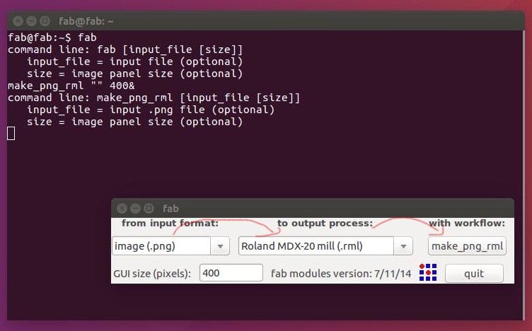
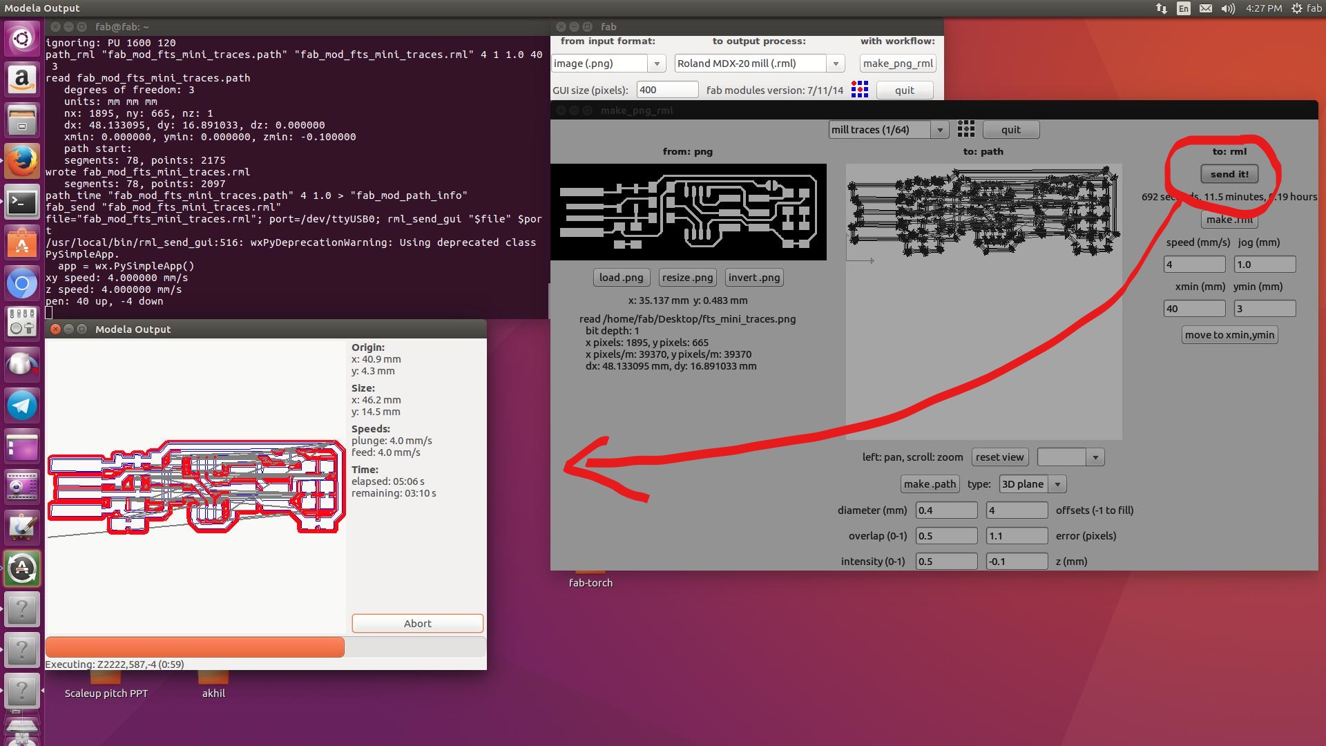
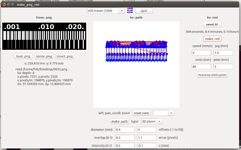
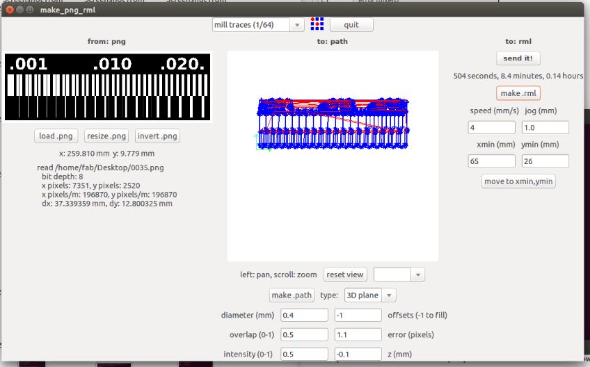
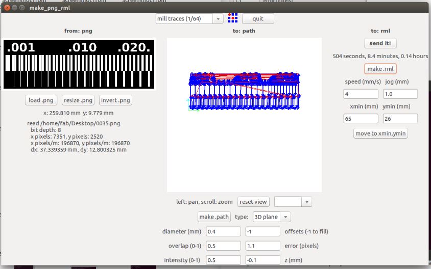
Now select "Image.png", set machine as "Roland MDX-20 mill(.rml)"" and enter "make_png_rml"
Now press "load png" and select the image that you wanna mill. Then select "mill traces(1/64)" and press "make.path". After processing press "make.rml" and prepare the PCB for milling.
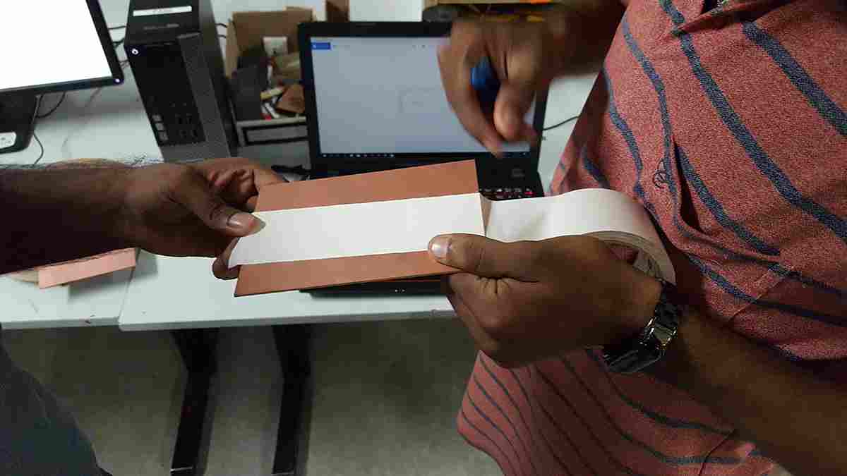
Setting-Up the PCB
Before we begin milling, first e have to prepare a PCB. For that attach a double sided tabe to a PCB and place it on the CNC mill. Attach a double sided tabe to the back of the PCB and stick it on to the sacrifical layer.
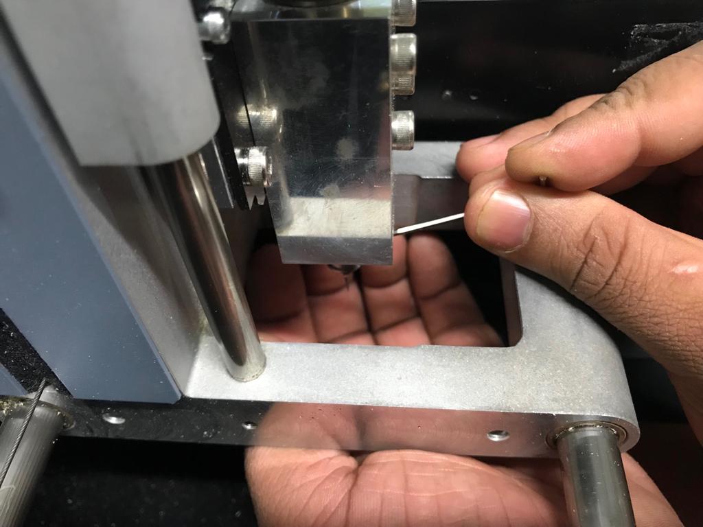
Now we have to setup the drill bits. For that I choose a V-bit (1/64) so that I can mill off the excess copper from my PCB. First adjust the bit into the holder pressing it all the way up.
Now move the "Y-axis" to the origin point using fab tools and correct X and Y cordinates..
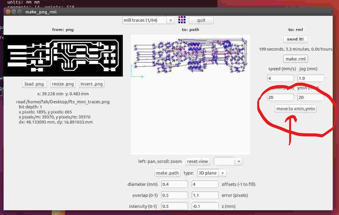
We are not done. Now we have to set the origin. For that press view button and adjust the bit's positon to the PCB..
Now we have our origin point. Remember this point for future cutting. Now press "make.rml" and you will get following window. Press start and it will start milling..
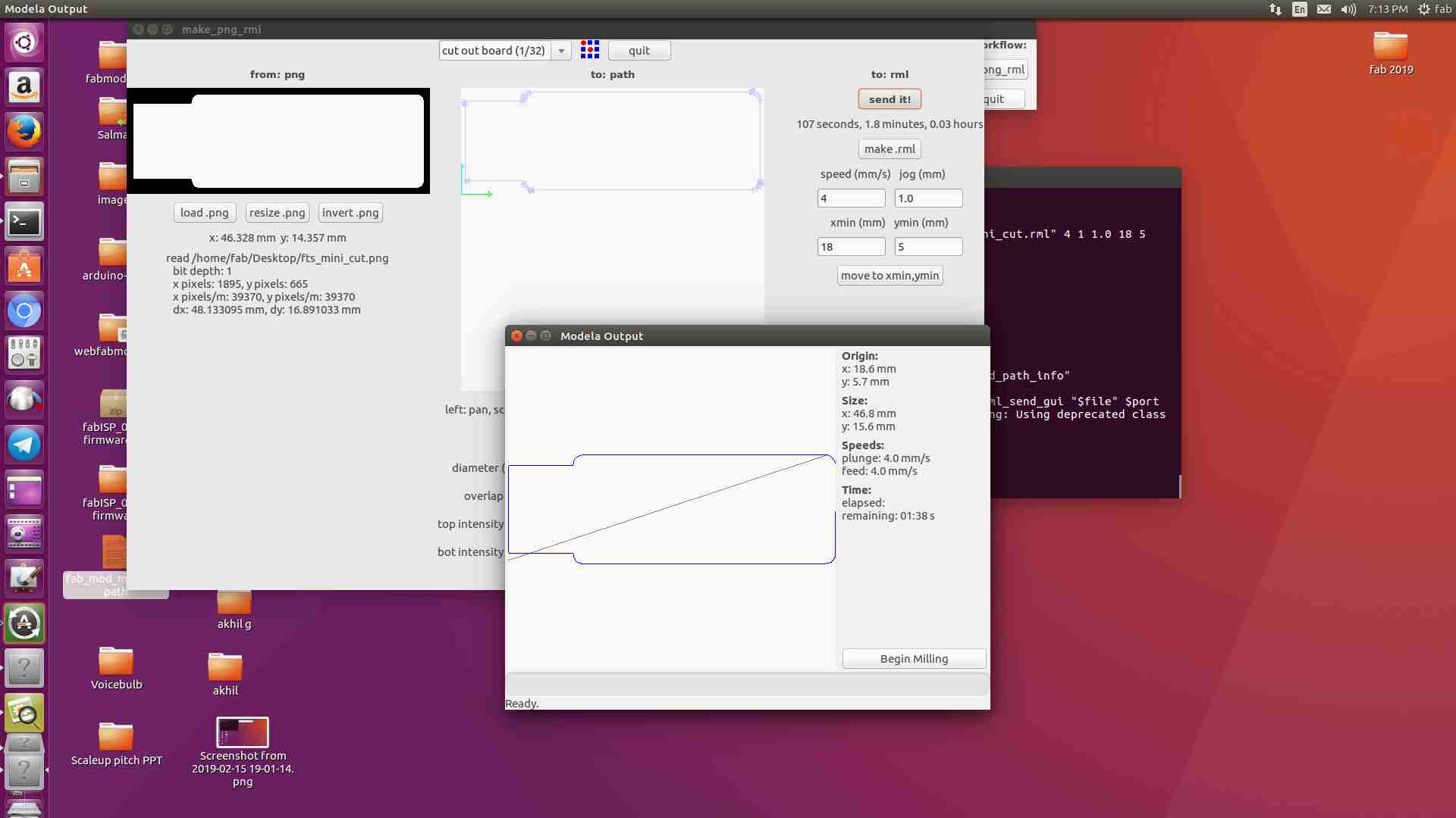
Now we have to cut the IST board out. For that first we have to load the image be cut. Afrer that we have to place the origin point on x,y cordinates. Chage the operation to "cut out board (1/32)" and "make_path".
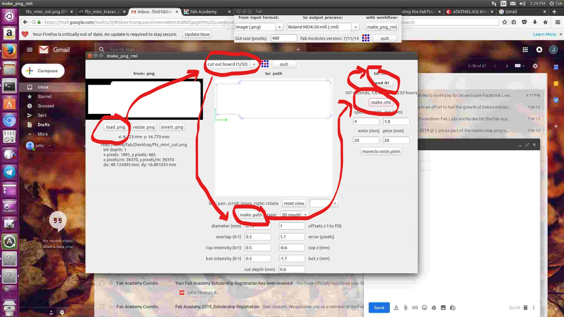
Now "make.rml" then send it . Following image pops up
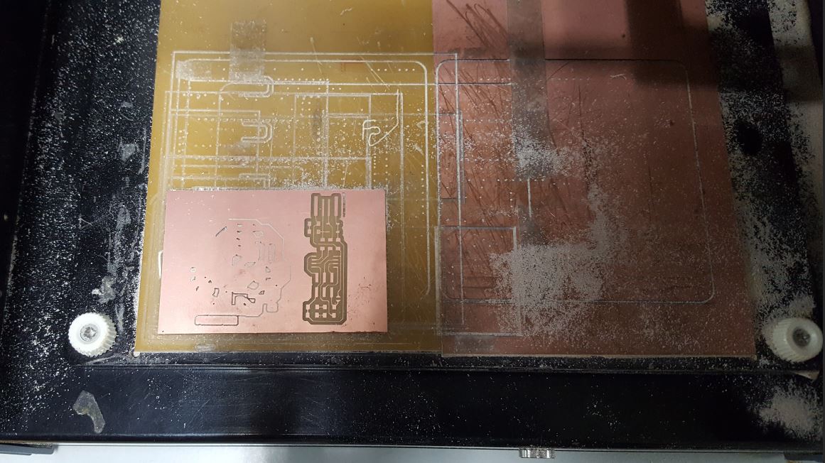
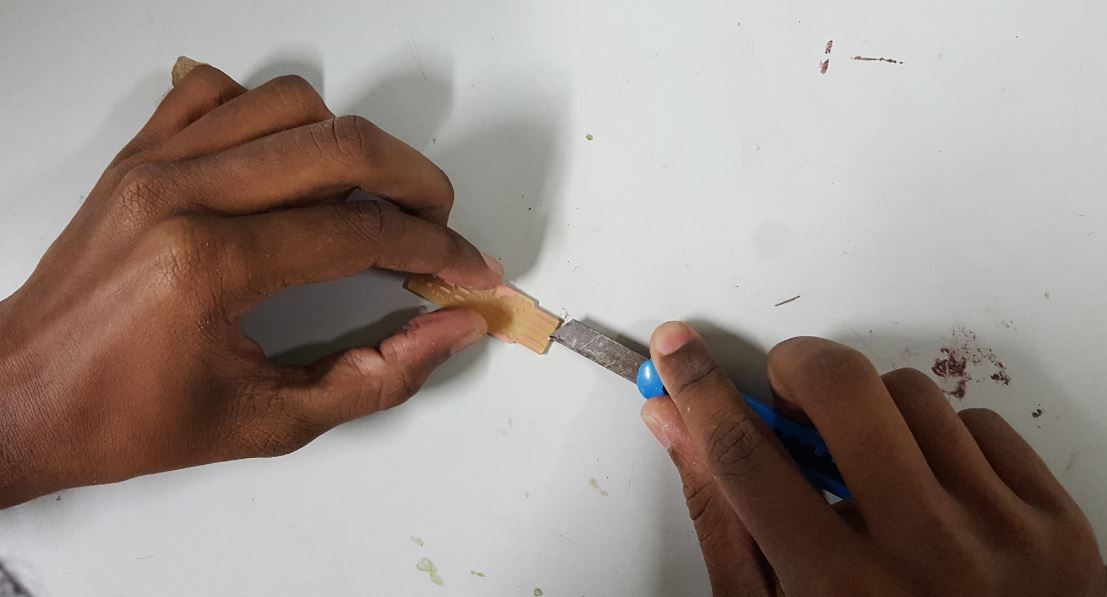
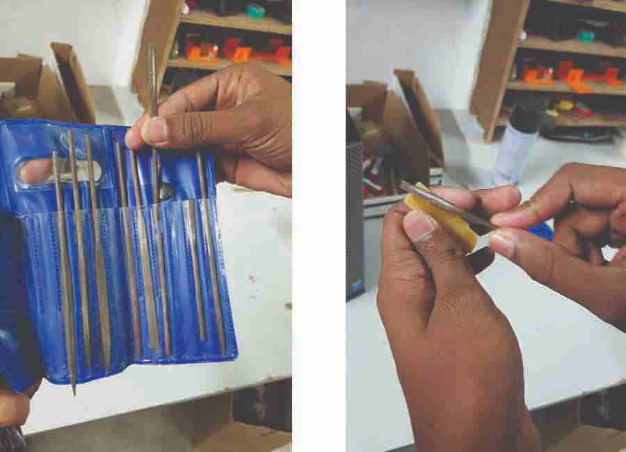
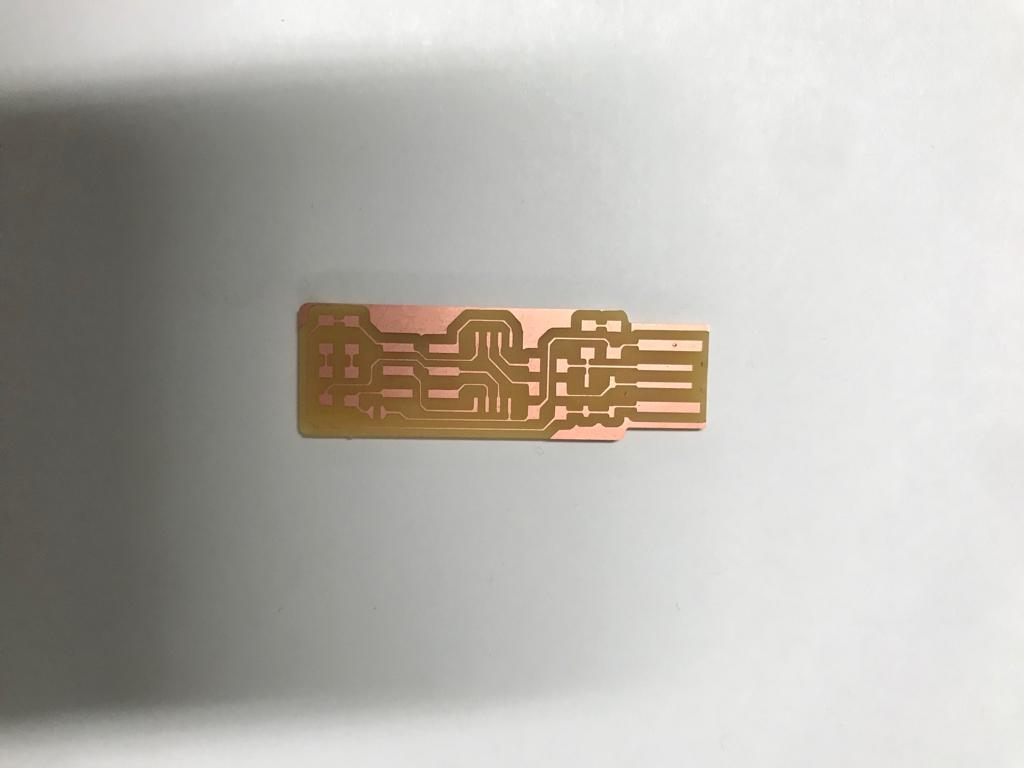
Now we got our pcb. But the edges are un-even and sharp. Take a file and shape it. Also remove un wanted parts
Now we got a finished board. Let move to soldering
soldering
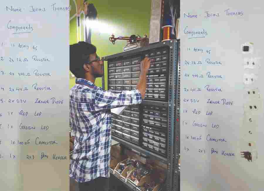
Soldering was a fun job. I am very good at soldering. so this task was very easy for me. I begin with making a list of the components that I am going to use.
Parts
Now go to inventory and pick up compnents and place them accoring to the list that you made
First I place the PCB on a bench wise. Now place some solder on the trace and place the components to solder to the PCB. I start with the IC and diodes. Because they had polarity.
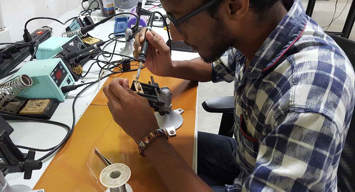
After that I solder every components one after an other. I got a good board after that.
Hero Shot
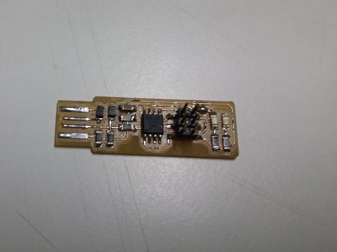
We got our ISP ready. Now it's time for programming it..
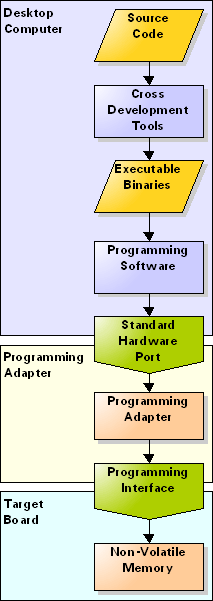
Programming ISP
What we make is just a hardware. It is useless without it's software part. So we need to upload the program code for the fabISP.I using Linux , so first we need to install avr-gcc tool-chain, type this on terminal to install tool-chian sudo
sudo apt-get install avrdude gcc-avr avr-libc make
After Installtion unzip the downloaded firmware and open terminal there.
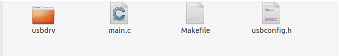
Now we can see the files , next we need to open the Makefile for ensuring it's configured for the ATTiny.i used nano to open the file ,
Just type..
nano Makefile
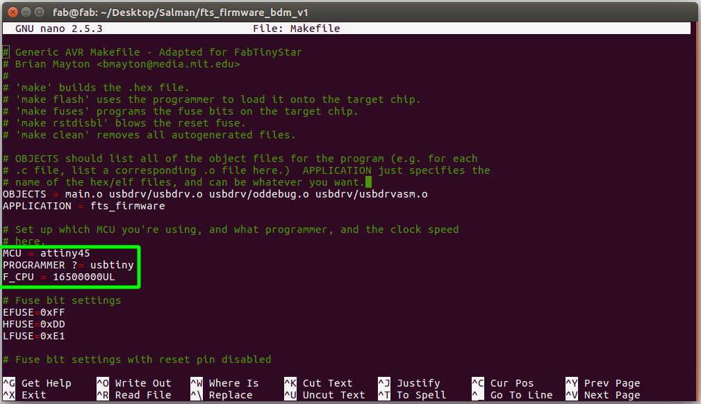
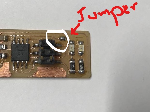
Now we can confirm that, it's configured for the ATTiny Before falshing make sure we are shorted the Progarmming Jumber on our PCB. and also make a Connector for ISP header,
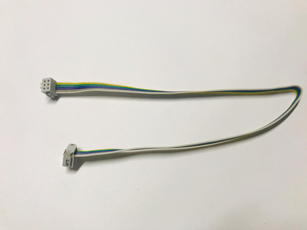
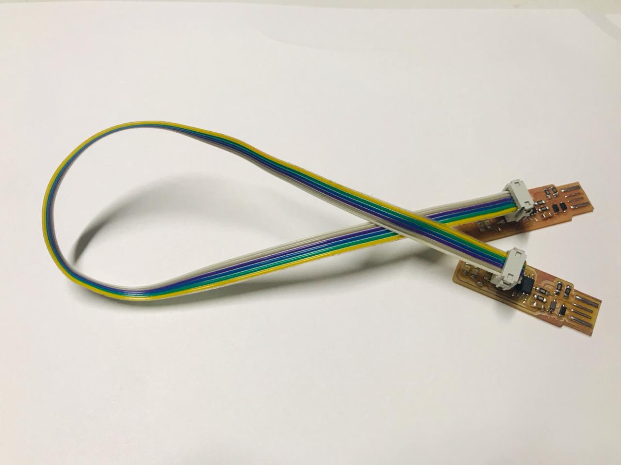
We need another Progarmmer for Progarmme the ISP Progarmmer , i used a previous student ISP to flash my ISP firmware.
In terminal (at the firmware file path) type
make
to Genarate the hex for flashing.

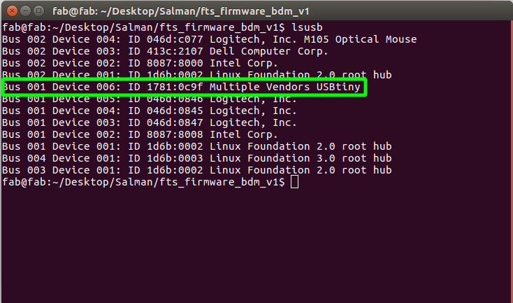
Now we can see some new files,that was automatically genarated make file script. Now Connect the Old ISP and connect to our new ISP. and check the new ISP was detected in Computer by Typing
lsusb
Now we are ready to flash.
Type,
make flash
to flash the firmware to new ISP.
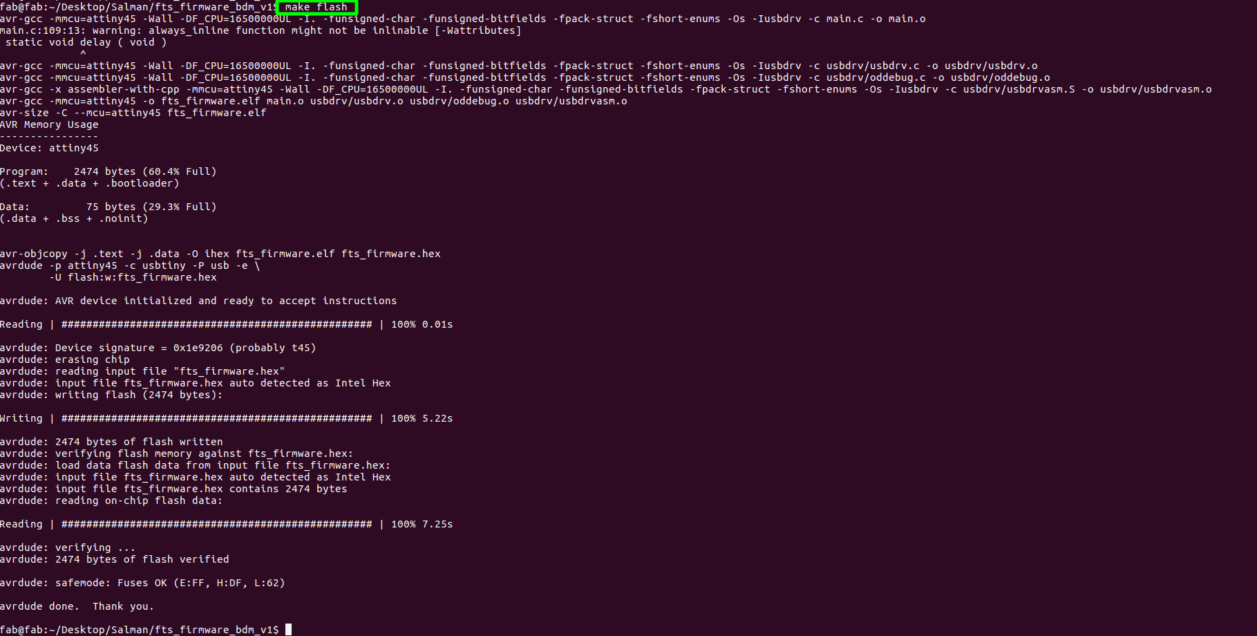
Now we are successfull flased.
We need activate the fuse in order to act our ISP as a progarmmer.For activating fuse,
make fuse
it will automatically , activate the fuse.
Now we have to remove the jumper from the board. Desolder the jumper connection.
Now we are all done. Let's wait for next electronics project....
Group Assignment
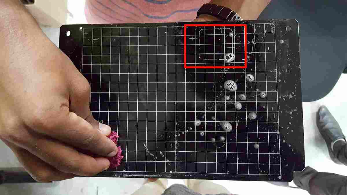
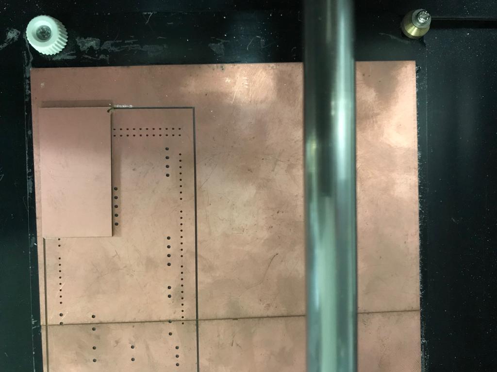
This Week we need characterize the specifications of our PCB production process i exaplined all procedure on the PCB Production section so next one is to find-out the how much resolution of 1/64 and 1/100 bit can mill and find out the difference.
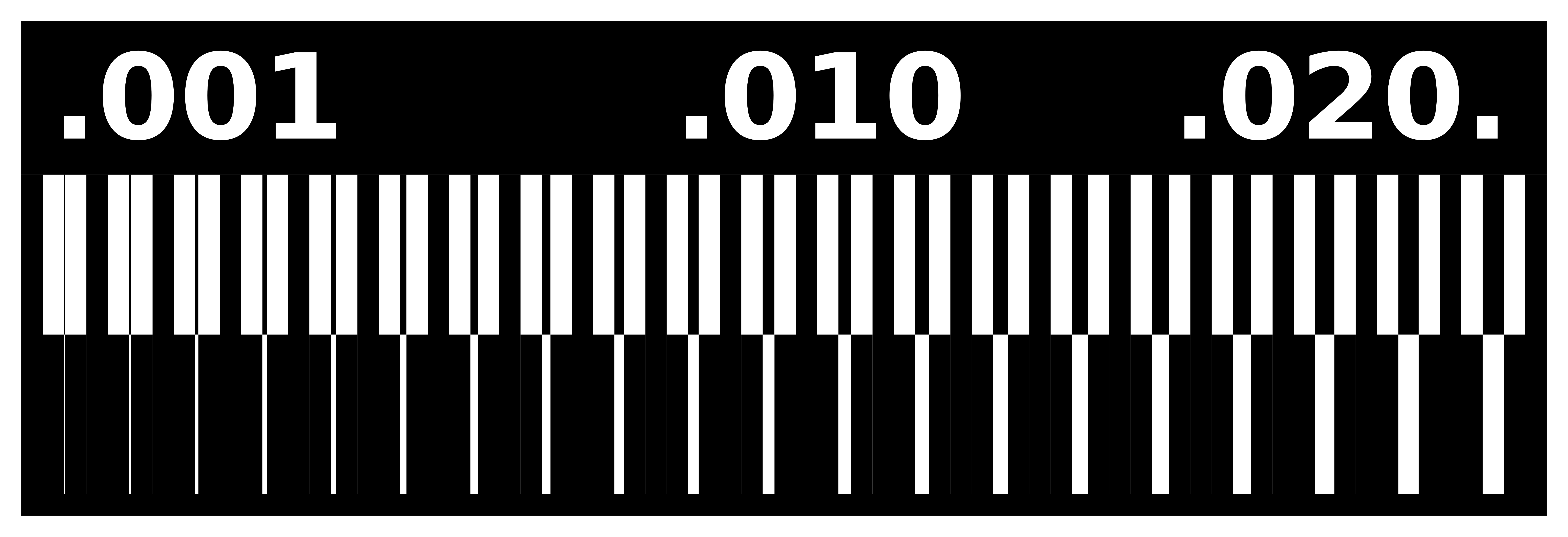
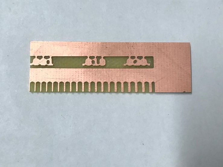
This is our test pad , so let's mill it.first i tried with 1/64 bit ,
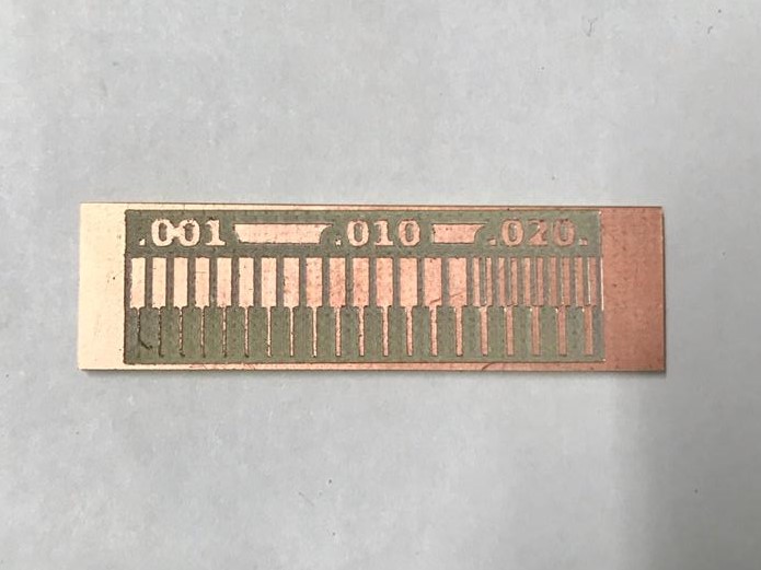
you can see here some copper part is not milled correctly,because i used offset as 4
Now i used offset as -1 , now you can see the path section now it's filled completed.
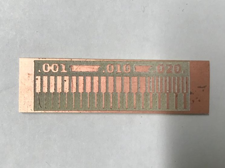
Now we got perfect one, there is no extra copper in this board , we can clearly see 1/64 only milled 0.20, and all other it's just passed.
So , next i tried with 1/32
and milled it
We can clearly see ,all this messed up with 1/32 . This images shows cleary the milling resolution of 1/64 and 1/32 bit .
So we have done woth Electronics production. See what comes in next week....