Mechanical / Machine Design
Introduction
Our first intention was to make a multipurpose cnc machine to be used for plotting,cutting etc. Since the time we had was very limited we decided to skip the same. Then our plan B was executed to make an arcade game. Since we were fans of arcade game, we searched for lot of arcade games in the internet. Finally we decided to make a game as below..
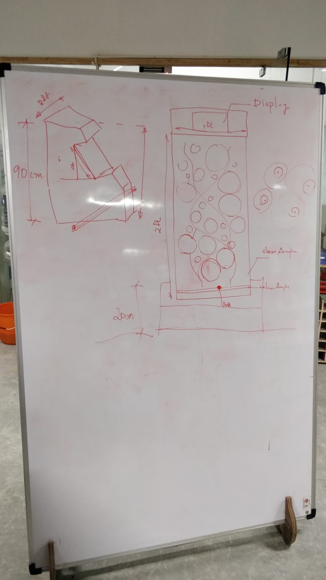
After designing of our concept, to our astonishment we found a very similar game named as 'ICE COLD BEER'.It seemed very similar to our concept...
Ice Cold Beer
Ice Cold Beer is a mechanical arcade game released by Taito in 1983. The game is in a similar cabinet to an arcade video game, but where the screen would normally be there is a vertical wooden playfield dotted with holes. Two joysticks on the control panel control the height of the two ends of a metal bar that moves up and down the playfield, with a ball bearing rolling back and forth on the bar. The playfield is an amber color, and the holes in the playfield are suggestive of bubbles rising in a mug of beer.
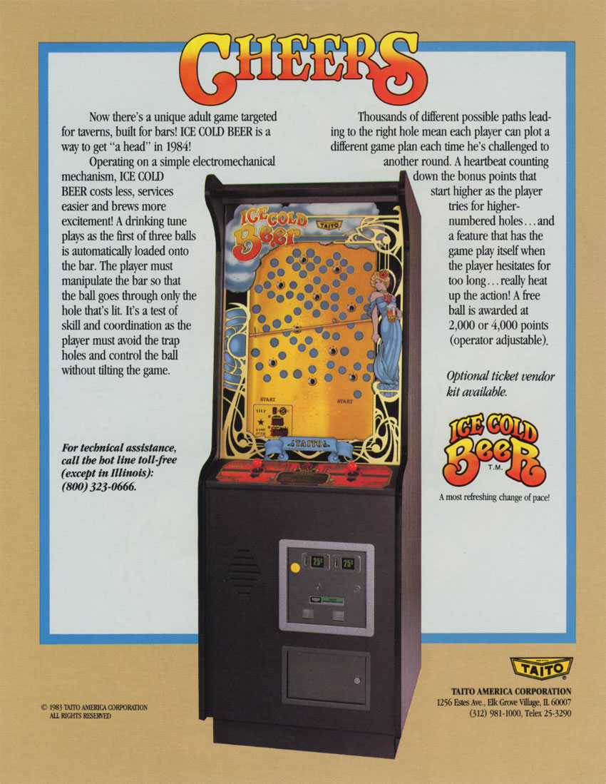
The objective of the game is to use the two joysticks to tip the bar back and forth and maneuver the ball up to a specific lit hole on the playfield, while avoiding unlit holes. When the player deposits the ball in the lit hole, the ball and the bar return to the bottom of the playfield, and the next target hole is lit. The game begins with the bottom-most hole lit, and subsequent lit holes become more and more difficult to reach while avoiding unlit holes.
Week 1: Mechanical Design
The moving parts were designed by Joel George Alex . So I was assigned to design the cover for arcade. So I designed the whole case from scratch. For that I choose Fusion 360. We started a share group in Fusion 360 to colaburate our designs.
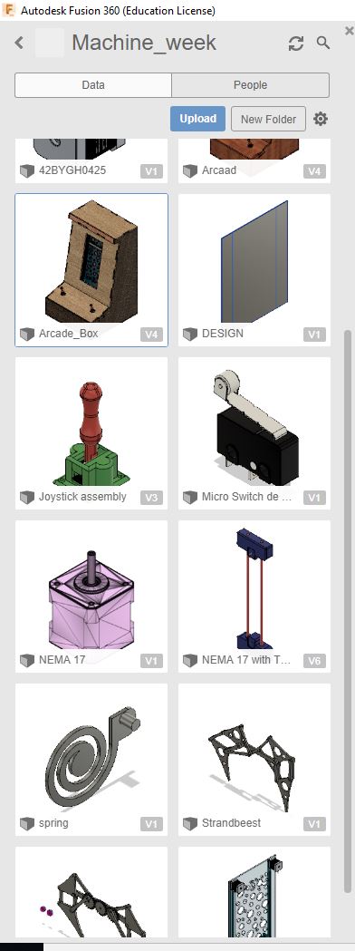
As I told you earlier, Jpoel has designed the mechanism. So I need to add the mechanism as a refference to my design. For that I opened the machine week in fusion 360 and open the mechanism...
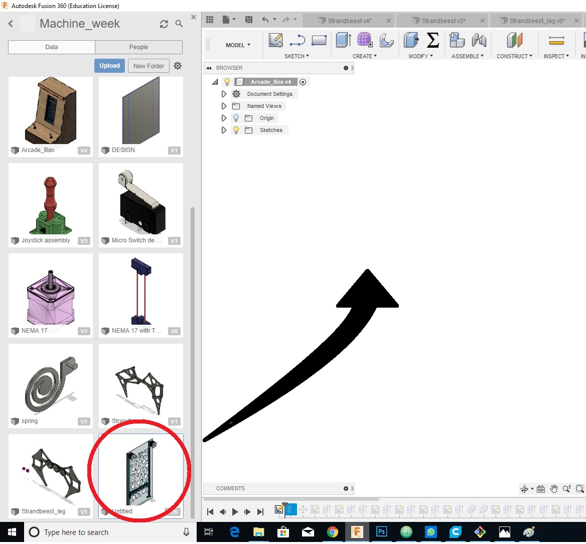
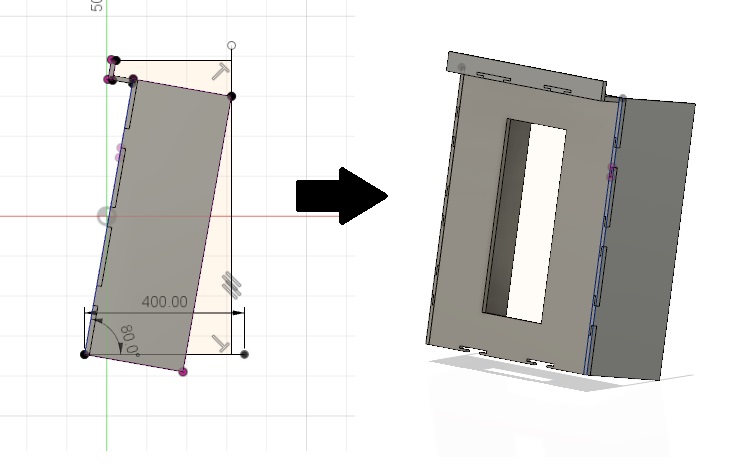
Now I need to create a basic sketch for the cover. I made an offset plane paralell to the mechanism. I made a basic sketch with refference as that. I extruded with a key slot for putting the other parts
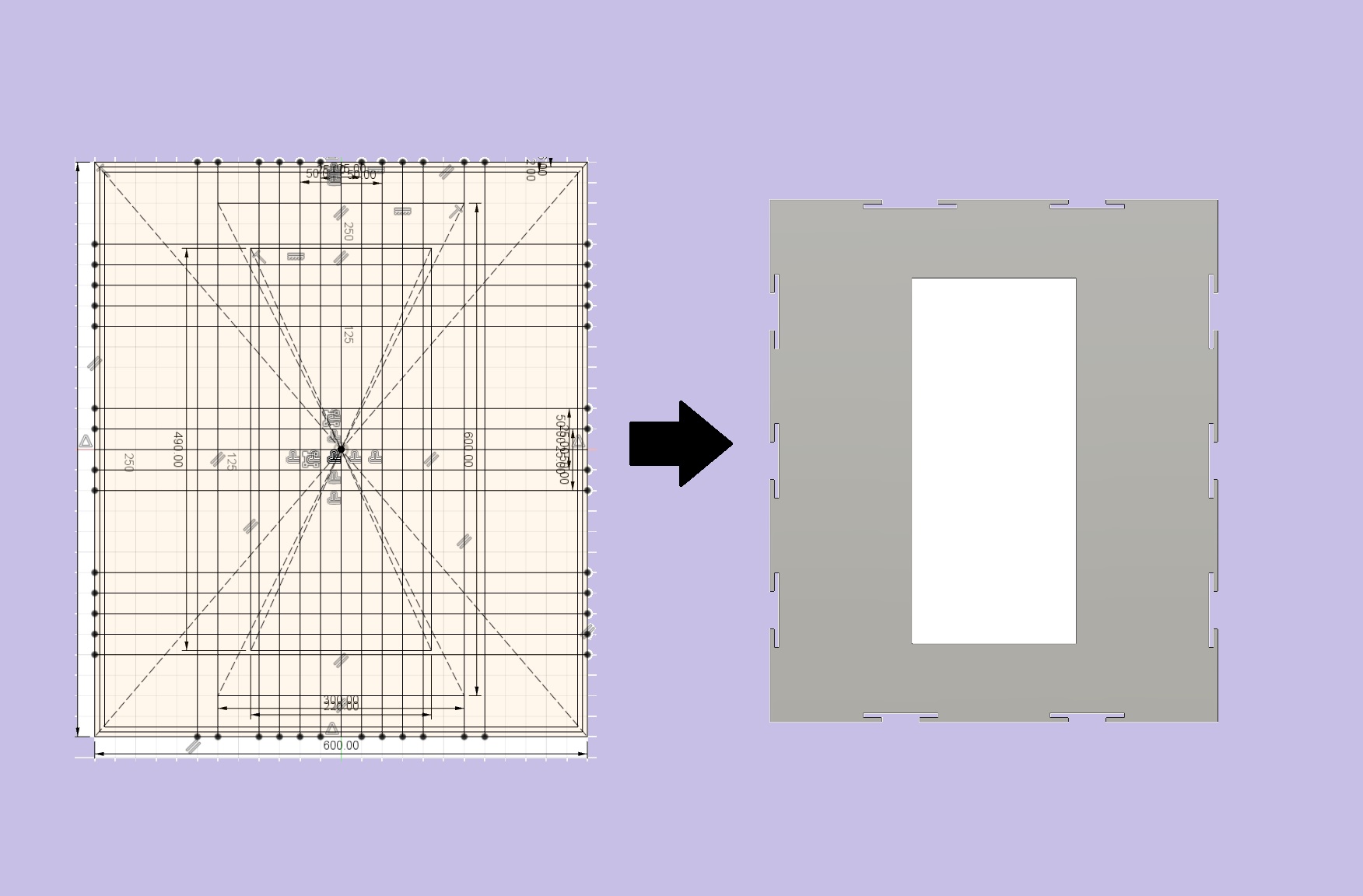
So in this way I made all the parts for the cover...
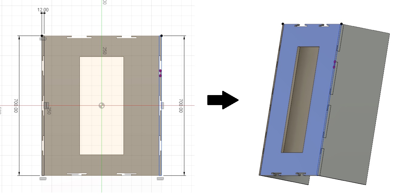
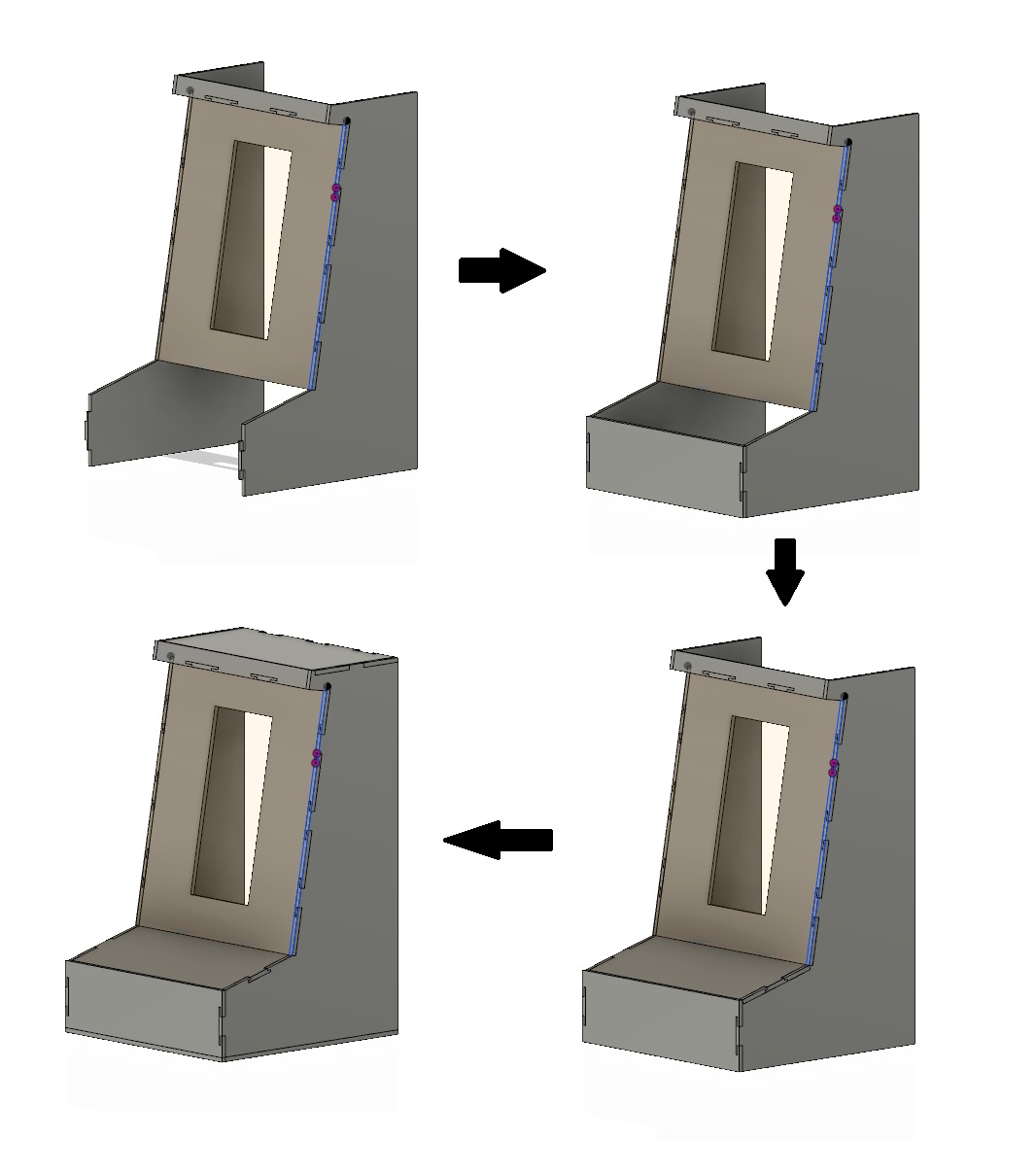
I have change view from front to side. Draw a side plate and etrude it
Now I redraw the joints and extrude it to join to the side faces. I have Also made an extension on the top..
extension to top from side view
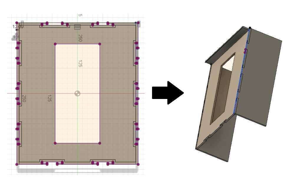
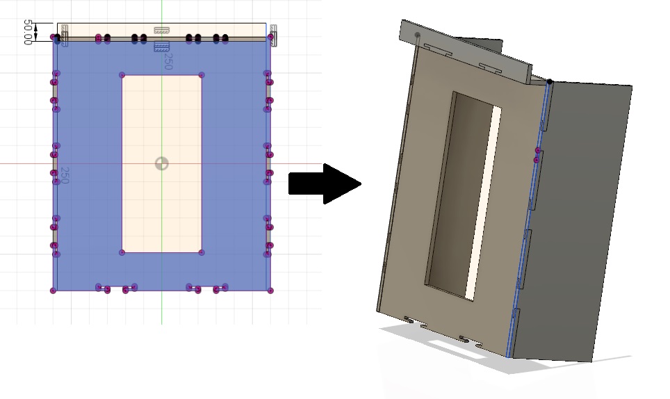
I drew a complete structure to fit the side. Also the front most plate and the control pannel plate...
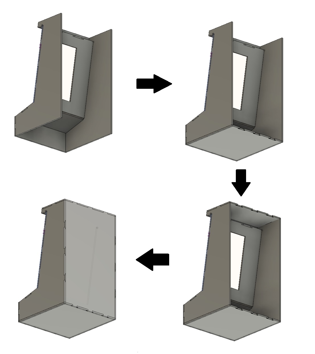
Now all it left to make the back, botom and top cover plates.
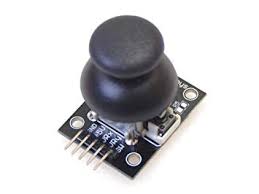
Now we need to add the joystick module for refference for the control pannel
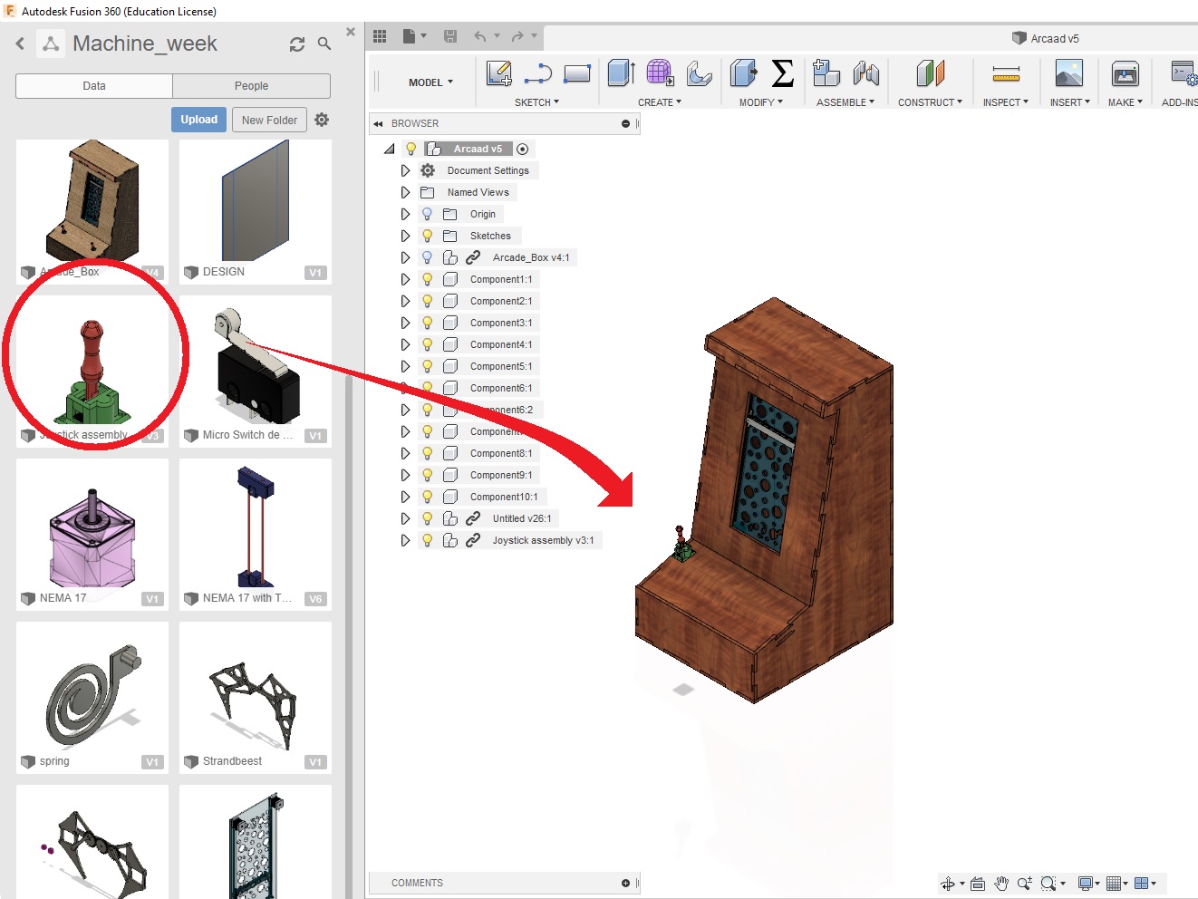
Now create a hole reference with the joystick. Align the joysticks with the control board and combined with the control pannel.
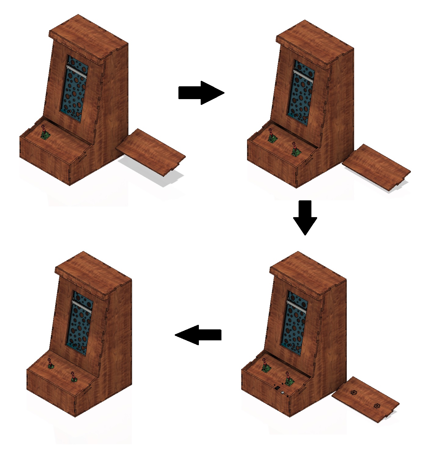
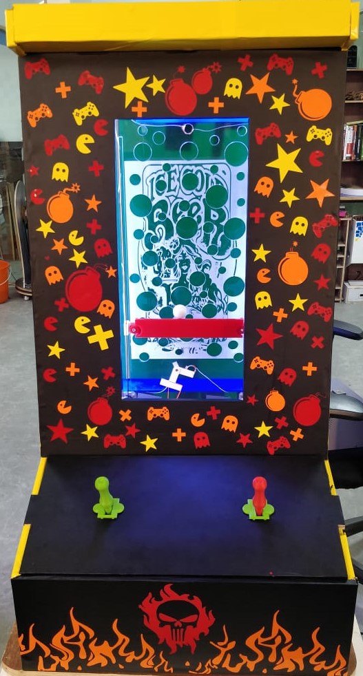
Here is the finished project..
You can download the design files from Here.
Machining
Now we need to cut the whole parts using a CNC machine. As I did in the Week 8 I loaded a 2440mm x 1220mm x 12mm wood on to the machine
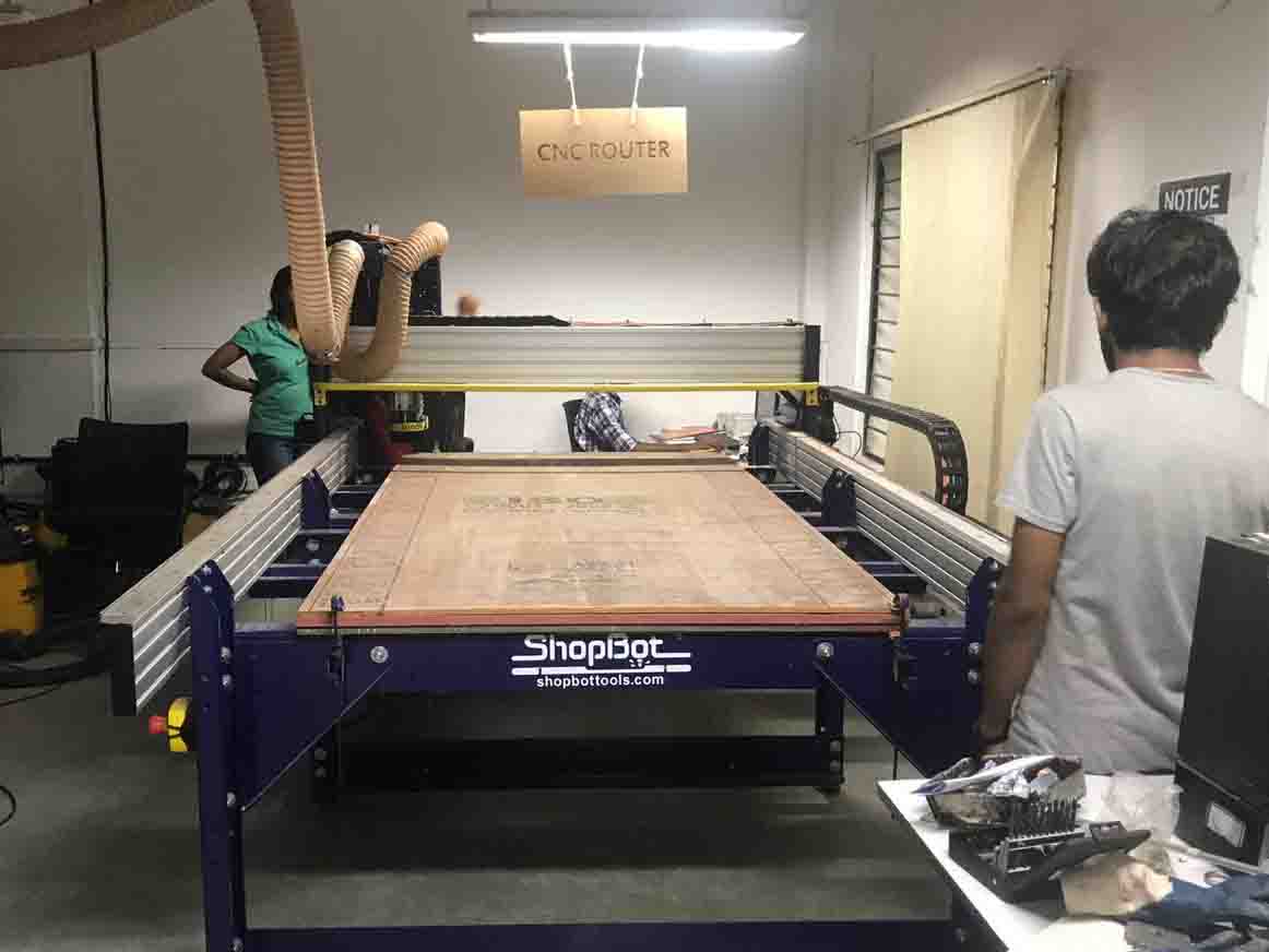
I screw the wood to the bed
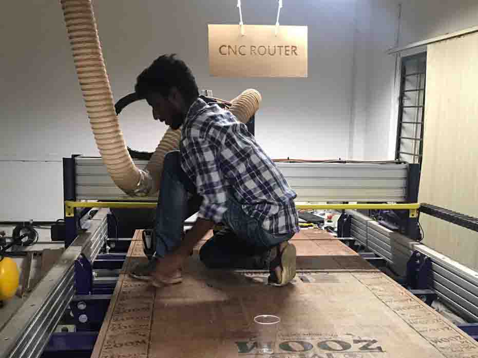
Now the setting is done and the machine started to cut
Afer cutting we clean the wood and remove excess..
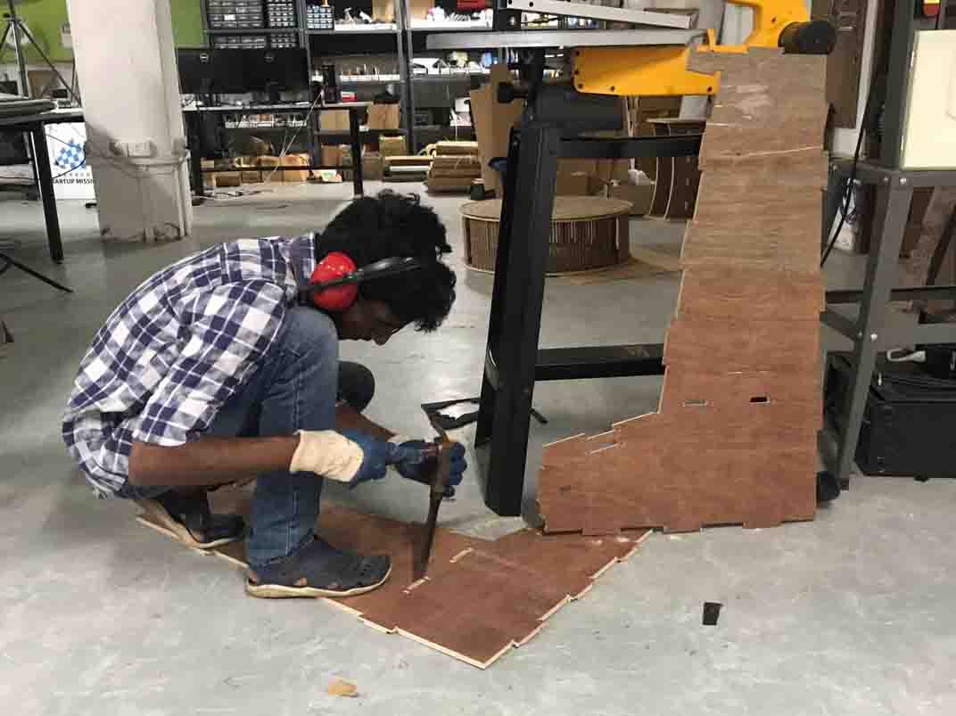
We started putting all to gether....
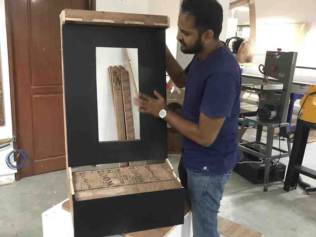
Here is the final view..
Week 2: Automation
We have completed the mechanical part last week. This week we are going to automate it. Fot that First I needed to know what is there to automate
So we have a list of things that need to be finished. Lets see what are we going to use for this project..
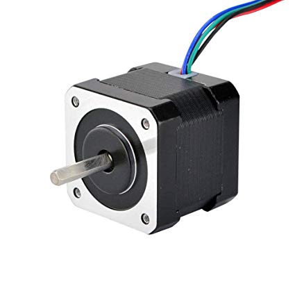
These are the important components we are going to use. So let's design the circuit.
Electronics Design
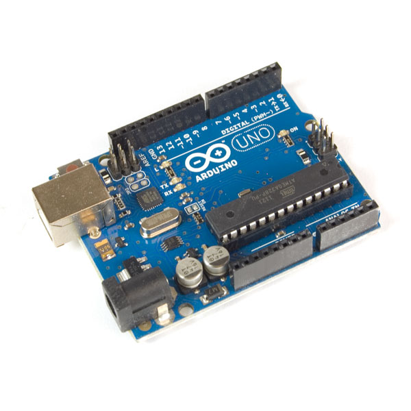
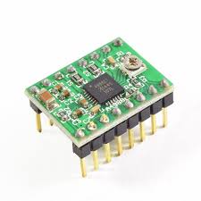
I started with the Arduino Uno board and the Stepper drivers.
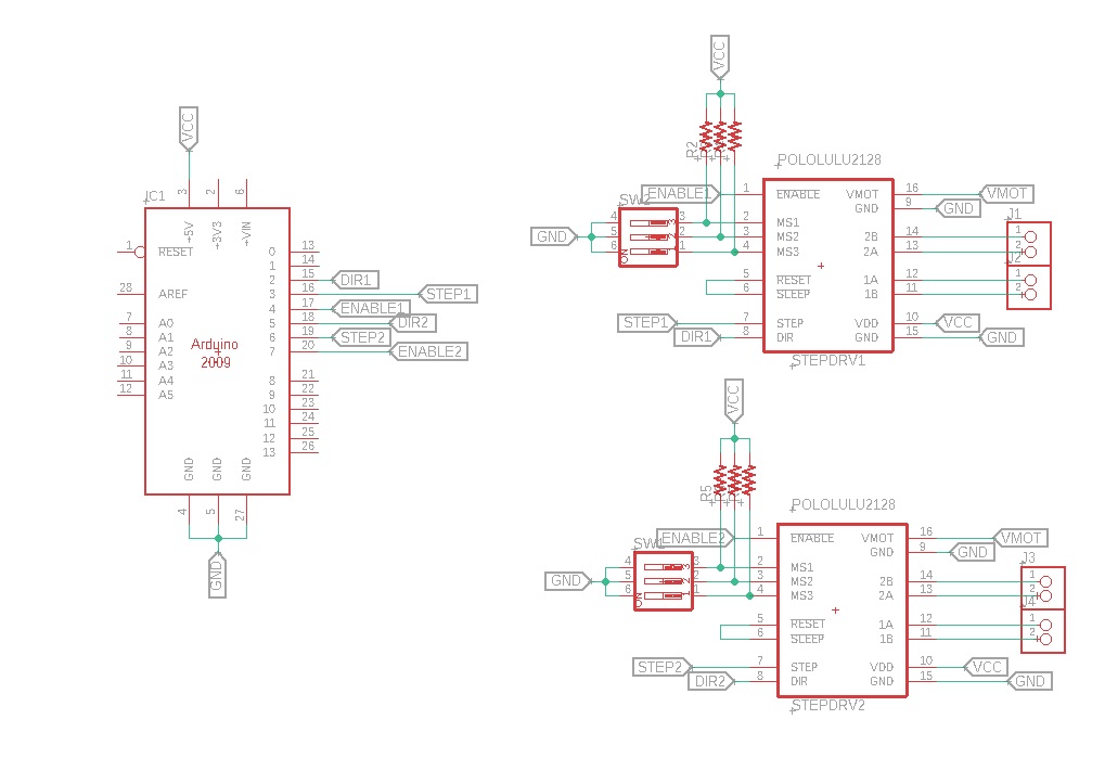
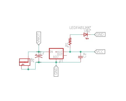
The whole controller needs 9-12 VDC and 5 VDC. So I have use a 5V regulator for poer didstribution. I have also given a Power Indicator LED as well.
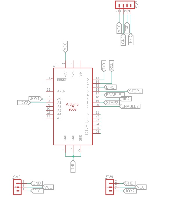
So power is designed. Now The communication part. In the system, we are only using 1 axis. so the joysick mdule doesnt need to be used for multi axes. So I have taken only the x axis value for reading here. Also i have given UART pin for communication purpose
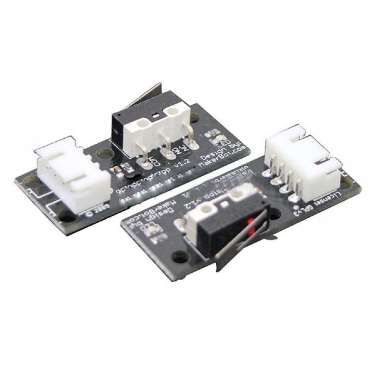
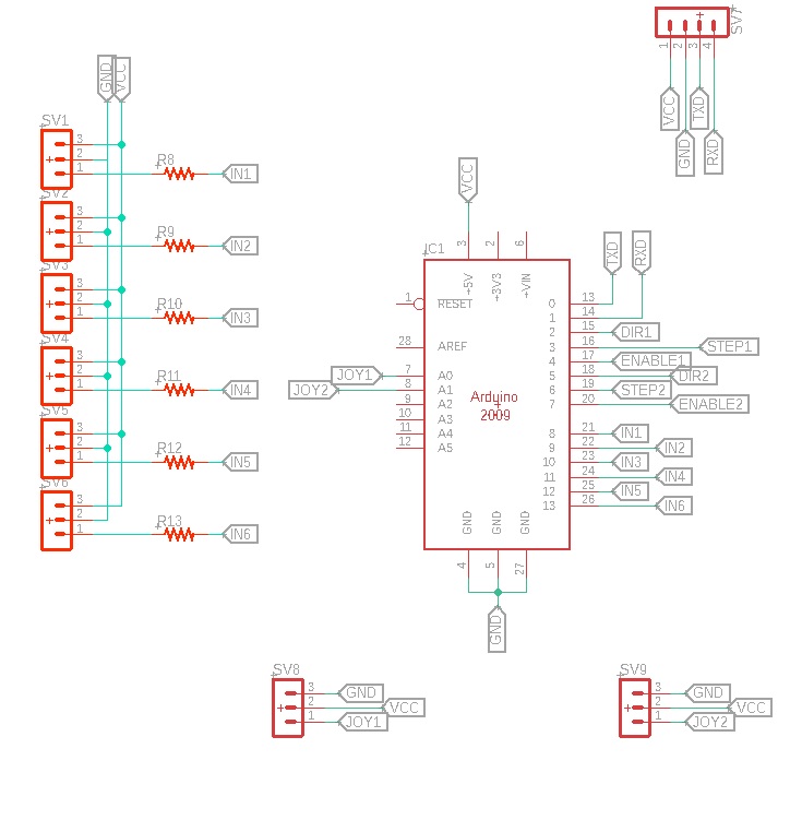
Now we needed to add the stoppers. For that we are using limit switches. Limit switch module have 3 ports. VCC, GND and DATA.
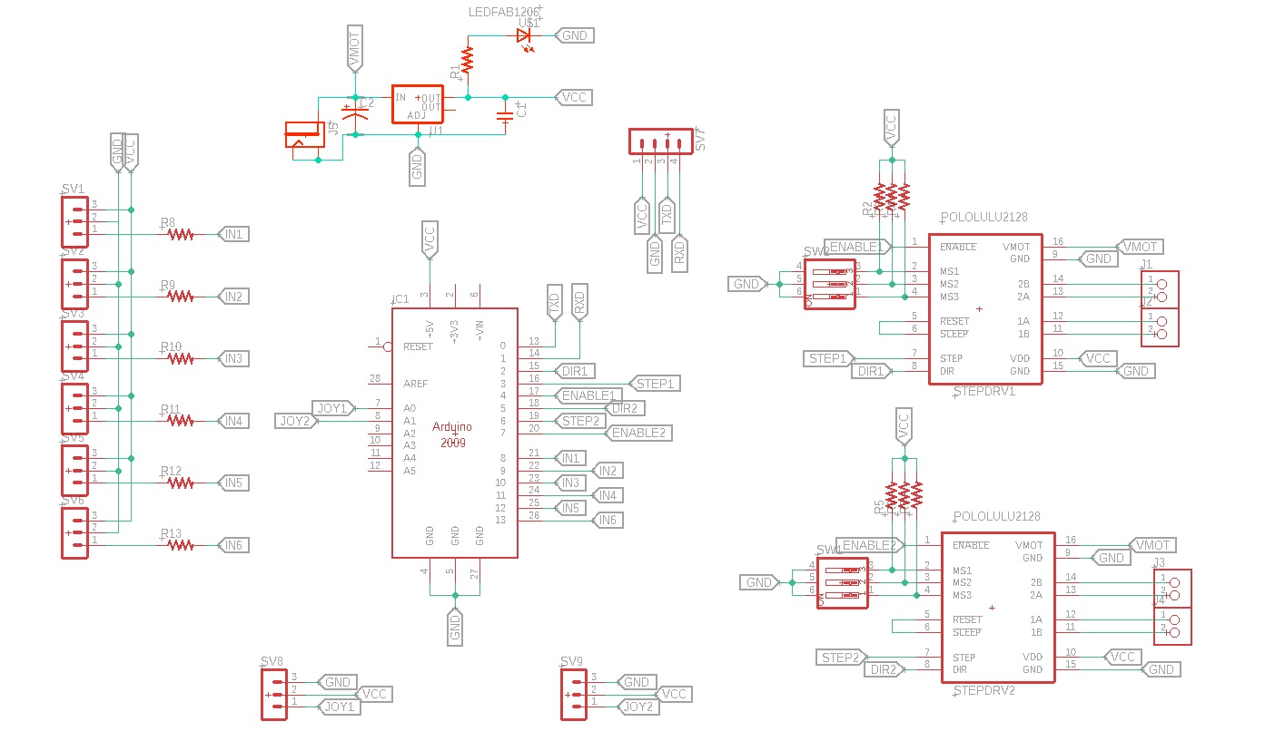
We put all these to gethor in a single circuit...
Schematics is ready. Now We can prepare the PCB. For that click the Switch to Board button
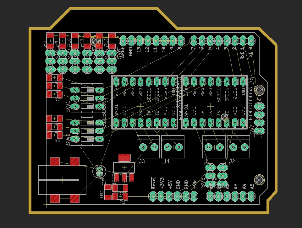
I have been using the manual routing method. So first I set the design rules for Modella MDX-20 and Route the power lines. The power lines are 32 mill and the signal lines are 16mill
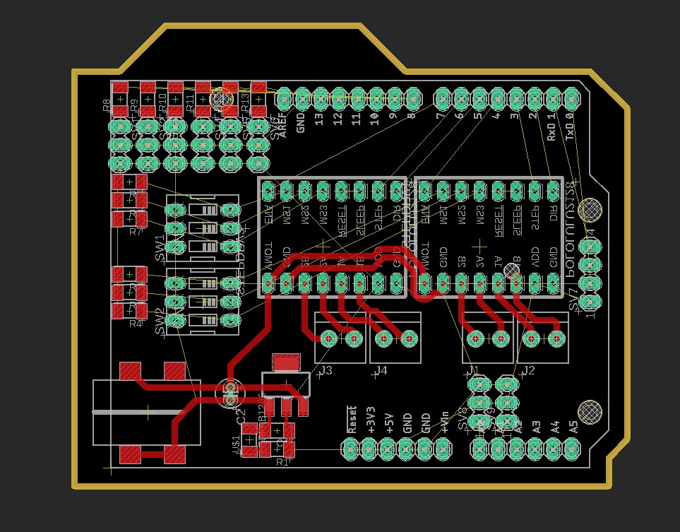
After finishing the power lines, we move to finish the signal lines
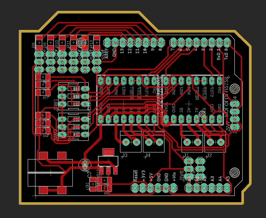
Here is the finished route
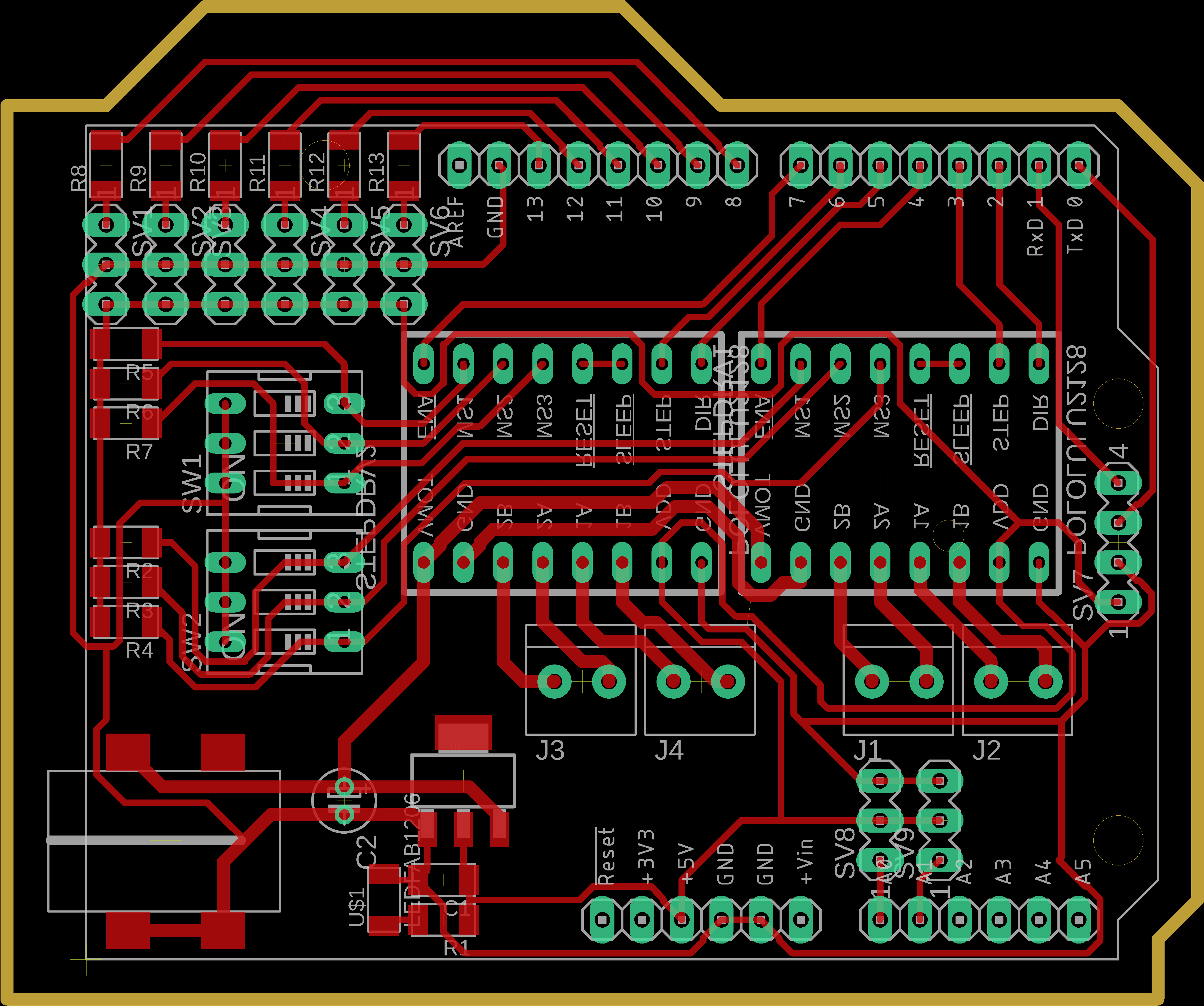
I have exported the files need for production as .png files
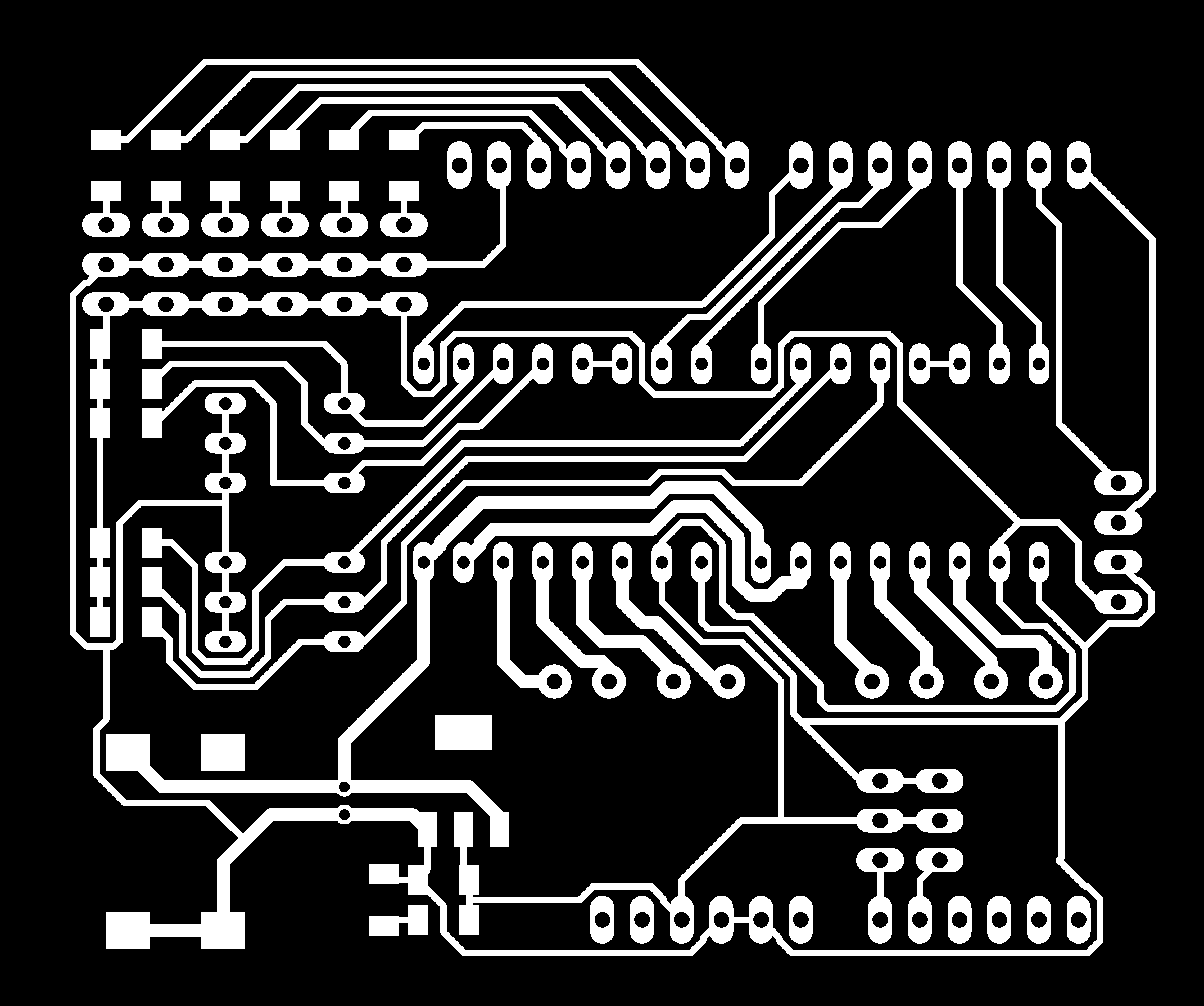
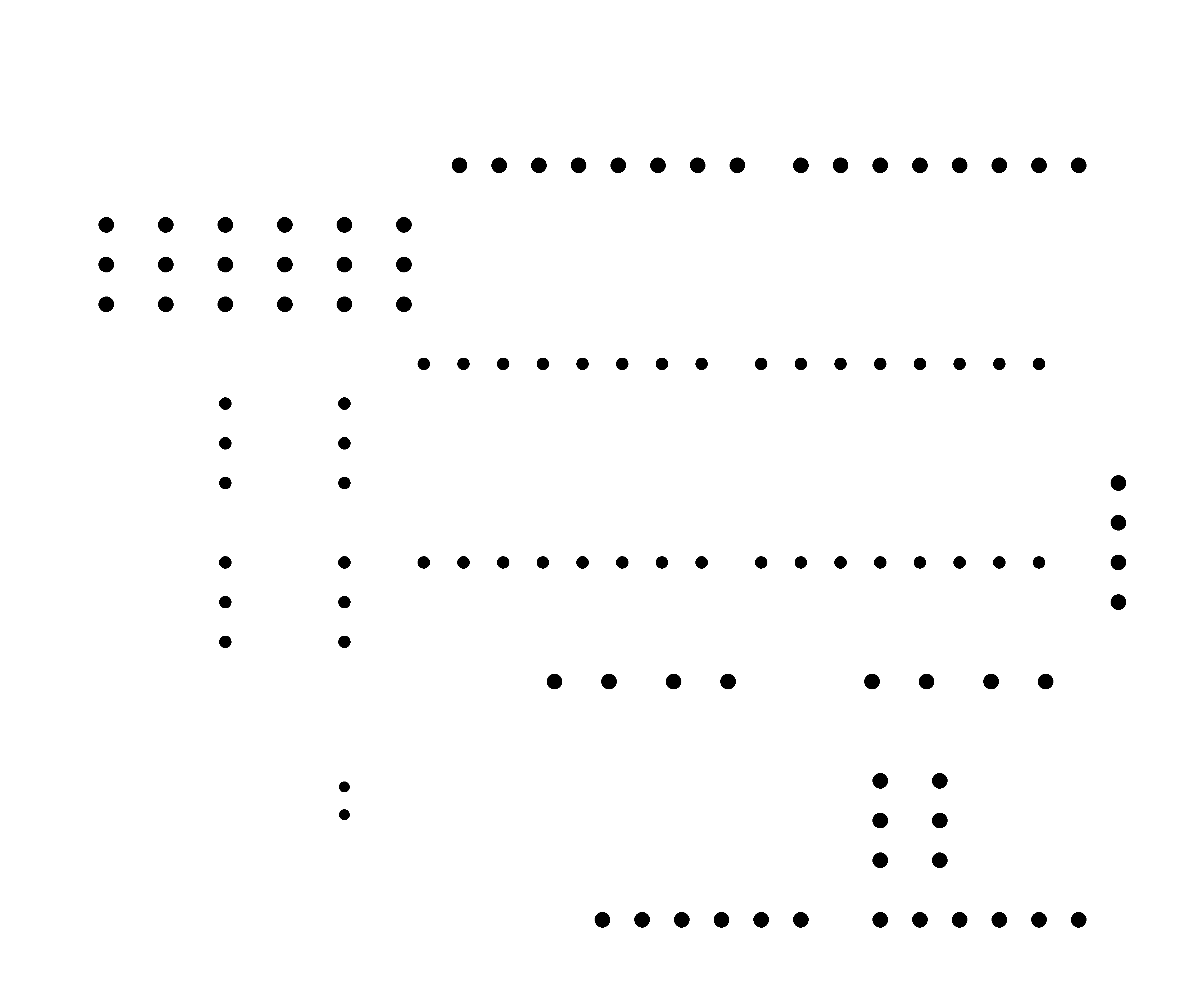
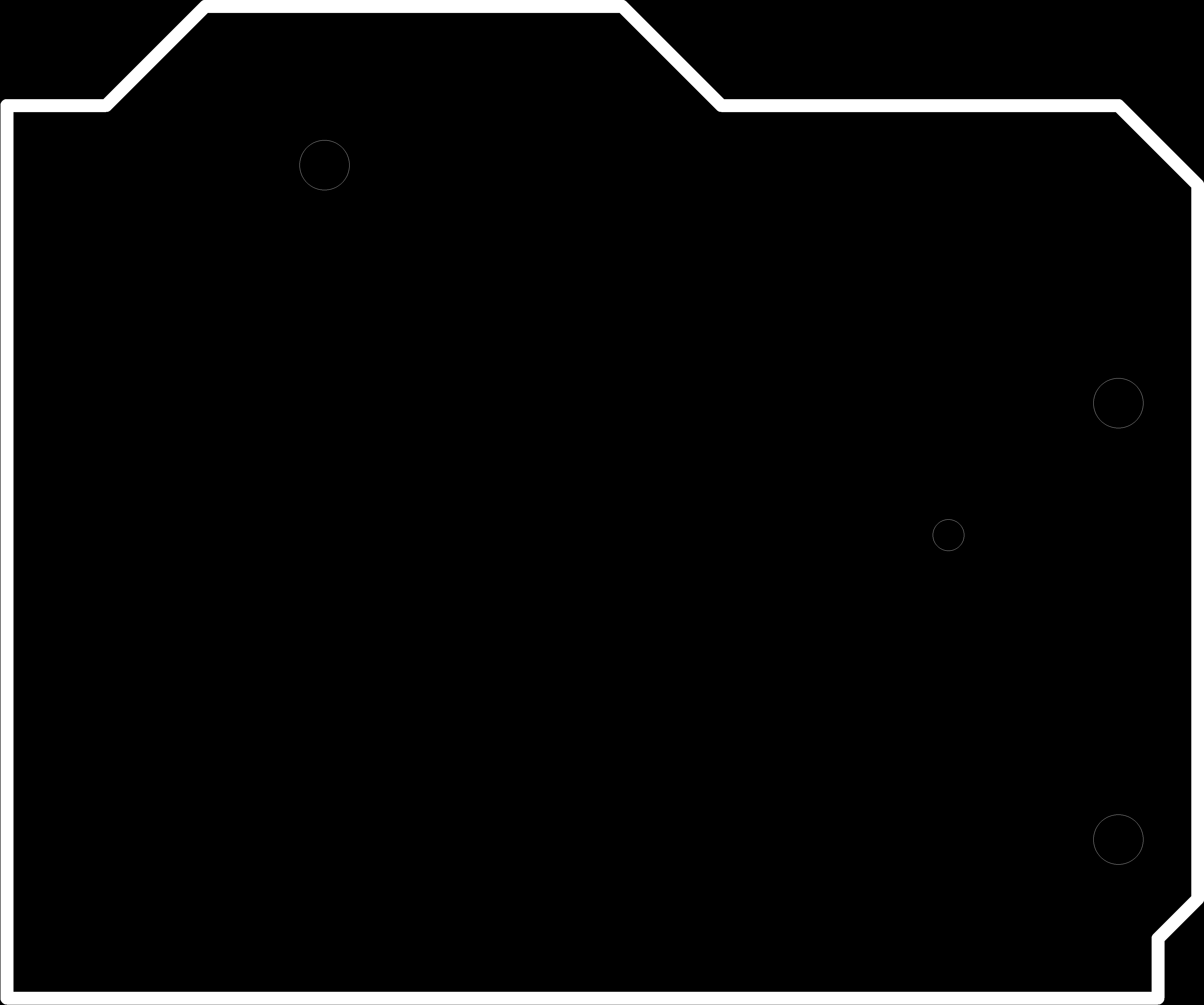
You can download the files from Here.
So let's mill the board...
PCB production was done by Akhil G Babu. Mechanical automation aws done by Joel George Alex. Tou can find the details on this Link.
Here is a testing video