
Embedded Programming
So it's the 9th week since I begin my fab journey. In this week, I got following assignments,
- Read a microcontroller data sheet
- Program your board to do something
- Experiment with other architectures
Introduction
This week we need to progarmme the Hello-echo board that we designed in the Electronics Design week. I have experience with the Arduino developement also i want to learn more pramming stacks so this is the best chance. in this week i wil progarmme the Echo-board with Arduino , C and also Assembly and i will document my experience here
Embedded System
An embedded system is a dedicated computer system designed for one or two specific functions. This system is embedded as a part of a complete device system that includes hardware, such as electrical and mechanical components. The embedded system is unlike the general-purpose computer, which is engineered to manage a wide range of processing tasks.
Microprocessor VS Microcontrollers
Microprocessor is a central processing unit (CPU) on a single chip. but in Microcontrollers it consist of CPU,Memmory Unit (RAM , ROM )and I/O's . but Microcontrollers is extremely slow when comparing Microprocessor .
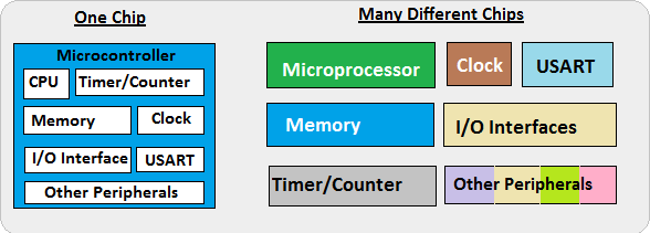
In here we are Focusing on Microcontrollers .
Hello-Echo board
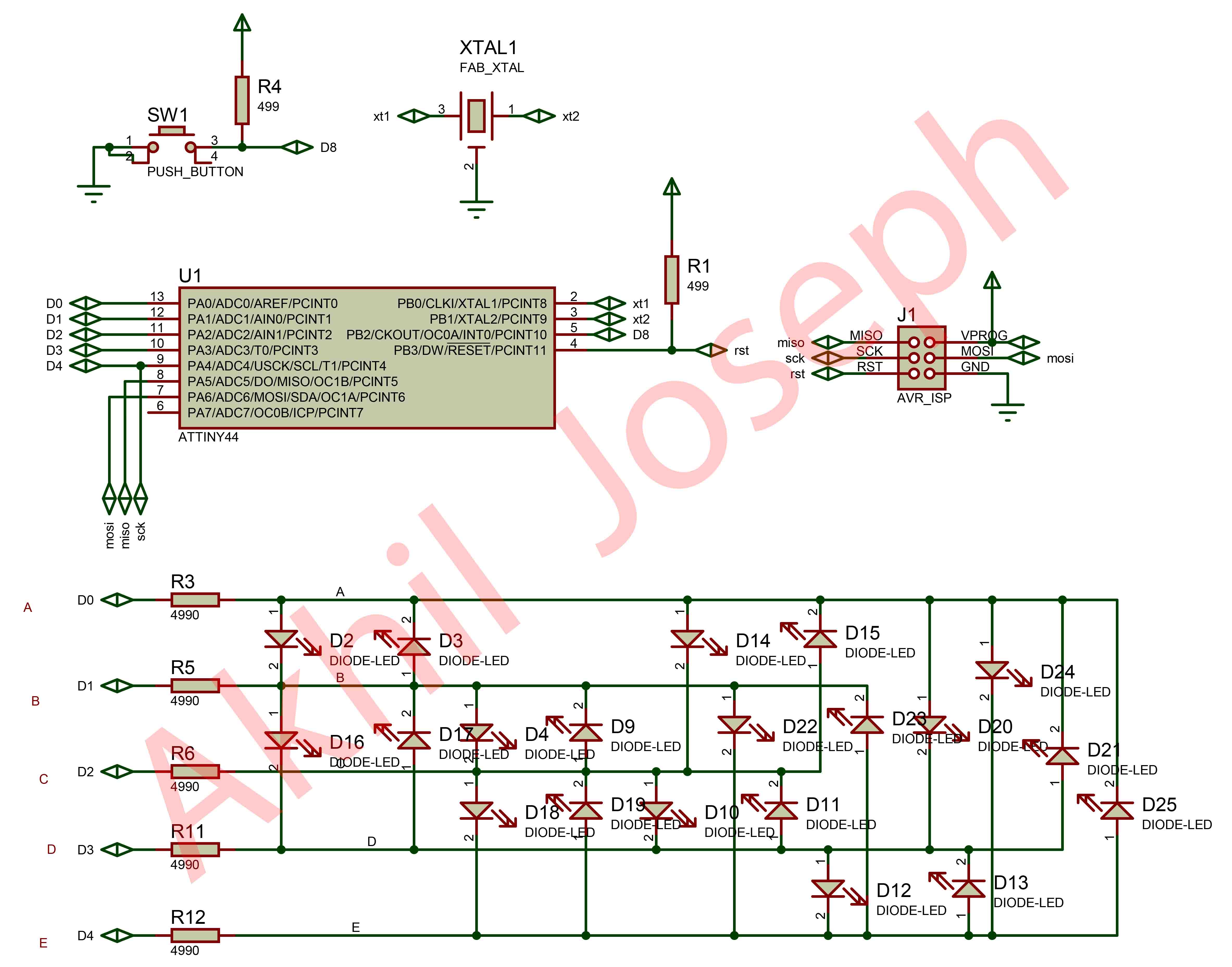
This week we need to progarmme the Hello-echo board that we designed in the Electronics Design week. Echo board is based on the Microchip ATtiny44 . It's a 8-bit RISC based microcontroller.The Originla Design have only the UART Port and I added e a Programmable Button connected to pin PA2 with a Pull-down Resistor and LED connectd to PA3 also it's have 20hz External Resonator
ATtiny44
It's a low power AVR® 8-bit microcontroller based on the RISC architecture.It have 12 GPIO pin's.
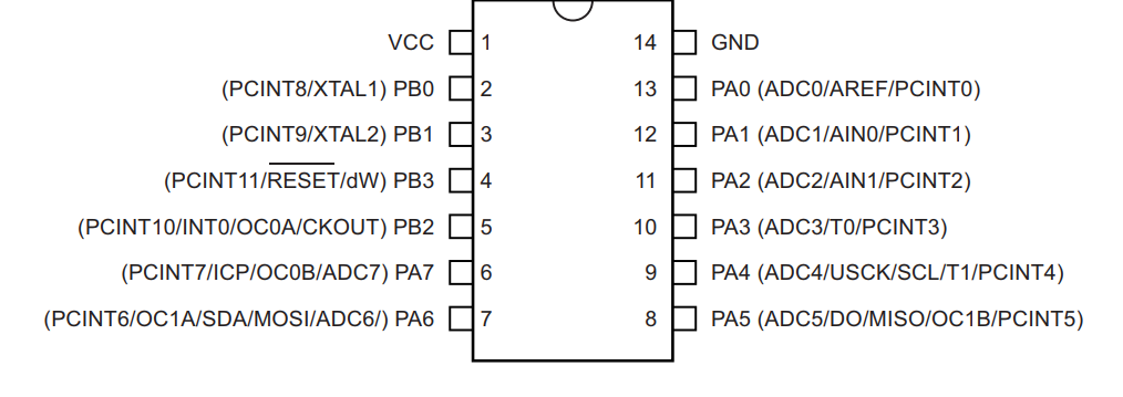
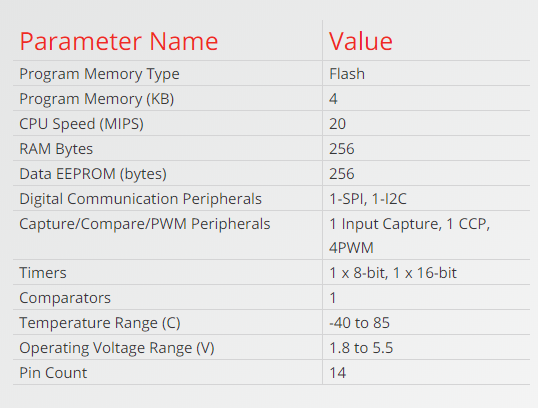
The Atmel ATtiny24/44/84 provides the following features: 2/4/8K bytes of in-system programmable flash, 128/256/512 bytes EEPROM, 128/256/512 bytes SRAM, 12 general purpose I/O lines, 32 general purpose working registers, an 8-bit Timer/Counter with two PWM channels, a 16-bit Timer/Counter with two PWM channels, internal and external interrupts, an 8-channel 10-bit ADC, programmable gain stage (1x, 20x) for 12 differential ADC channel pairs, a programmable watchdog timer with internal oscillator, internal calibrated oscillator, and three software selectable power saving modes
The best Guide to know about a microcontroller and Instruction set it's Datasheet.we will get all the information from the Datasheet , only problem is it's not a beginner friendly. I started Reading ATtiny44 Datasheet that i got from the Micorchip website. Here you can Download it .
For Six -Wire ISP Programming of ATtiny 44 using six pins shown in below
- SCK(Serial Clock): Programming clock, generated by the In-System Programmer (Master)
- MOSI(Master Out - Slave In ): Communication line from In-System Programmer (Master) to target AVR being programmed (Slave )
- MISO( Master In - Slave Out ): Communication line from target AVR (Slave) to In- System Programmer (Master)
- RST(Reset): To enable In-System Programming, the target AVR Reset must be kept active. To simplify this, the In-System Programmer should control the target AVR Reset
- GND(Ground): Common Ground
Block Diagram
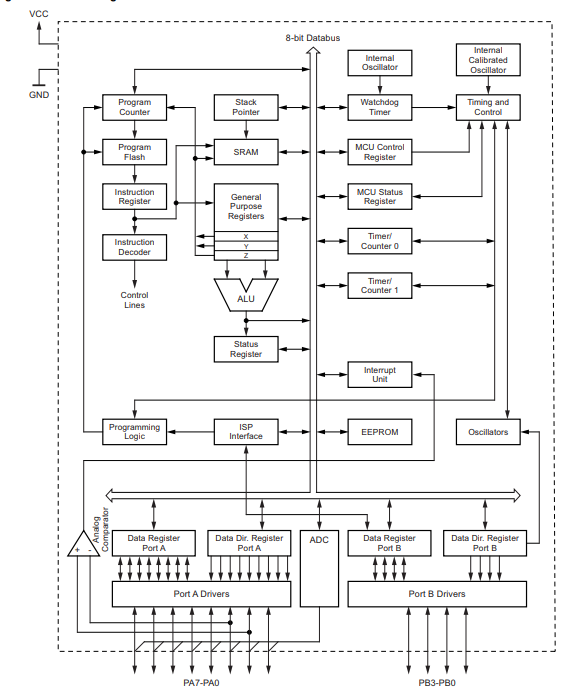
Block Diagram will explain Architecture of the Microcontroller.The AVR uses a Harvard architecture, with separate memories and buses for program and data. Instructions in the program memory are executed with a single-level pipelining. While one instruction is being executed, the next instruction is pre-fetched from the program memory. The ALU supports arithmetic and logic operations between registers or between a constant and a register. Single-register operations can also be executed in the ALU. After an arithmetic operation, the status register is updated to reflect information about the result of the operation.we wil go through all the Stacks when we comes to Progarmme the chip.
Embedded Programming
There is several ways to progaramme a AVR Microcontroller. Easiest one is using Arduino IDE and there is Microchip Official tool one Atmel Studio also we have toolchain in GCC.First we are using Arduino IDE.We are using the FabTiny ISP as our Progarmmer .
Arduino
Arduino is an open-source electronics platform based on easy-to-use hardware and software.ou can tell your board what to do by sending a set of instructions to the microcontroller on the board. To do so you use the Arduino programming language (based on Wiring), and the Arduino Software (IDE), based on Processing.Anyone can use Arduino. The Arduino system is based on the avr-gcc compiler and makes use of the standard AVR libc libraries, which are open-source C libraries, specifically written for Atmel hardware.You can downdload the Arduino IDE here.now arduino also have Online IDE.
By default the arduino software doesnt contain Attiny 44 chip librarys. We need to include the deatils manually.
In windows we need to install the SPI interface driver , you can download driver here .
- Install and Open Arduino IDE
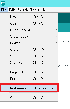
- Open preference by clicking
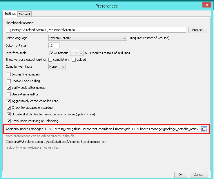
File >> preference - In Additional Board Manager URls add the Following URL
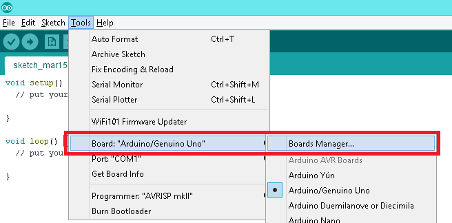
https://raw.githubusercontent.com/damellis/attiny/ide-1.6.x-boards manager/package_damellis_attiny_index.json - After adding the URL open Board Manager by clicking
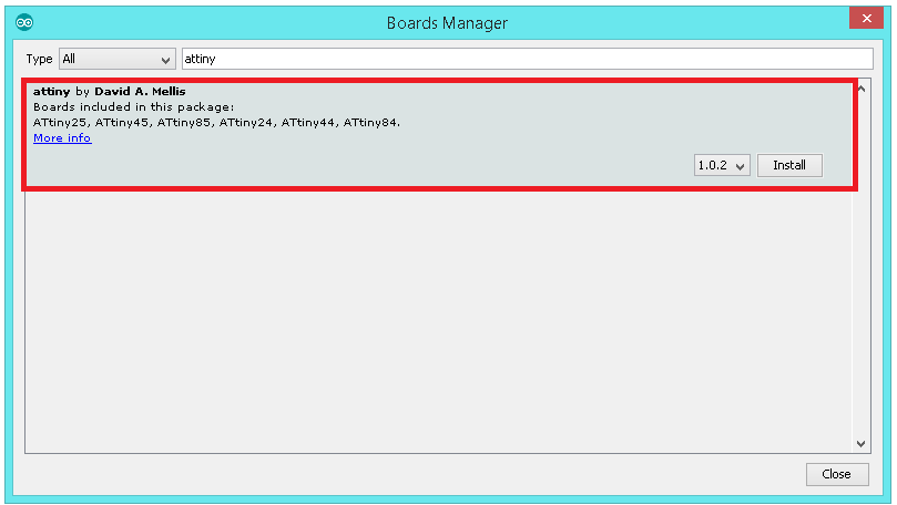
Tools >> Board >> Board Manager - Search for ATtiny44 in the following Window.(Make sure you have Internet connection).and Install the latest version .
- Now you can select ATtiny44 under the ATtiny Microcontrollers in board Selection
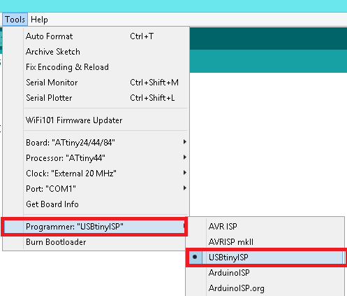
- Select appropriate Clock and Programmer.
Arduino Code
  #define A 0
  #define B 1
  #define C 2
  #define D 3
  #define E 4
  #define DELAY 500
  int c[5][4][2] =
  {
    { {A, E}, {B, E}, {C, E}, {D, E} },
    { {A, D}, {B, D}, {E, D}, {C, D} },
    { {E, C}, {A, C}, {D, C}, {B, C} },
    { {E, B}, {D, B}, {C, B}, {A, B} },
    { {E, A}, {D, A}, {C, A}, {B, A} }
  };

  int frames[][5] =
  {
    { 0b0101,
      0b0101,
      0b0111,
      0b0101,
      0b0101
    },
    { 0b0111,
      0b0100,
      0b0111,
      0b0100,
      0b0111
    },
    { 0b0100,
      0b0100,
      0b0100,
      0b0100,
      0b0111
    },
    { 0b0111,
      0b0101,
      0b0101,
      0b0101,
      0b0111
    }
  };
  void setup()
  {
    pinMode( A, INPUT );
    pinMode( B, INPUT );
    pinMode( C, INPUT );
    pinMode( D, INPUT );
    pinMode( E, INPUT );
    test_loop();
  }
  void setup2()
  {
    pinMode( A, INPUT );
    pinMode( B, INPUT );
    pinMode( C, INPUT );
    pinMode( D, INPUT );
    pinMode( E, INPUT );
  }
  void display( int frame[5], int duration )
  {
   int times = 0;
   int x = 0;
   int y = 0;
   while( times < duration )
    {
      for( y = 0; y < 5; y++ )
      {
        for( x = 0; x < 4; x++ )
        {
        setup2();
        if( frame[y] & (0b100 >> x) )
        {
          light( c[y][x] );
          delayMicroseconds(DELAY);
          times++;
        }
      }
     }
    }
  }
  void light( int pins[2] )
  {
    pinMode( pins[0], OUTPUT );
    digitalWrite( pins[0], HIGH );

    pinMode( pins[1], OUTPUT );
    digitalWrite( pins[1], LOW );
  }
  void test( int pins[2] )
  {
    setup2();
    light(pins);
    delay(50);
  }
  void test_loop()
  {
    test(c[0][0]);
    test(c[0][1]);
    test(c[0][2]);
    test(c[0][3]);
    test(c[1][0]);
    test(c[1][1]);
    test(c[1][2]);
    test(c[1][3]);
    test(c[2][0]);
    test(c[2][1]);
    test(c[2][2]);
    test(c[2][3]);
    test(c[3][0]);
    test(c[3][1]);
    test(c[3][2]);
    test(c[3][3]);
    test(c[4][0]);
    test(c[4][1]);
    test(c[4][2]);
    test(c[4][3]);
  }
  void loop()
  {
    test_loop();
  }
Click Upload to flash the Hello-Echo Board .

Programming ATMEL STUDIO
Studio 7 is the integrated development platform (IDP) for developing and debugging all AVR® and SAM microcontroller applications. The Atmel Studio 7 IDP gives you a seamless and easy-to-use environment to write, build and debug your applications written in C/C++ or assembly code. It also connects seamlessly to the debuggers, programmers and development kits that support AVR® and SAM devices.
Additionally, Studio includes Atmel Gallery, an online app store that allows you to extend your development environment with plug-ins developed by Microchip as well as third-party tool and embedded software vendors. Studio 7 can also seamlessly import your Arduino sketches as C++ projects, providing a simple transition path from Makerspace to Marketplace.
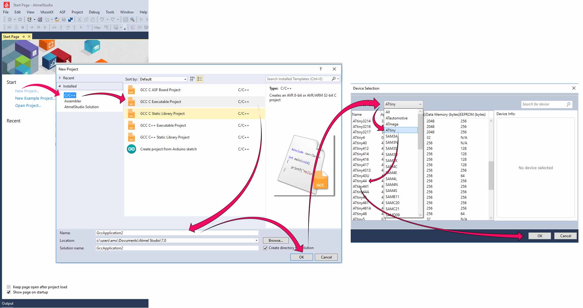
To start a new project .Just open the software and choose new project .Select Gcc C Executable Project . Then select a name and click Ok . Select Our Chicp from the next window and click on the okey button. Now the enviournment is created
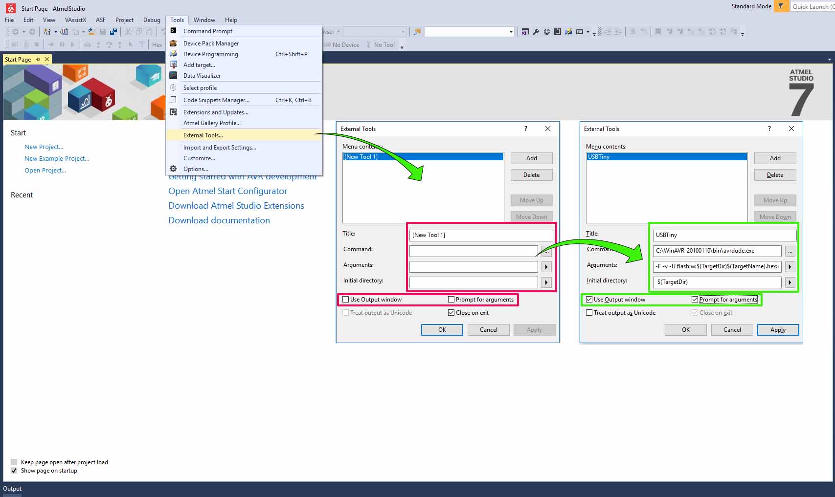
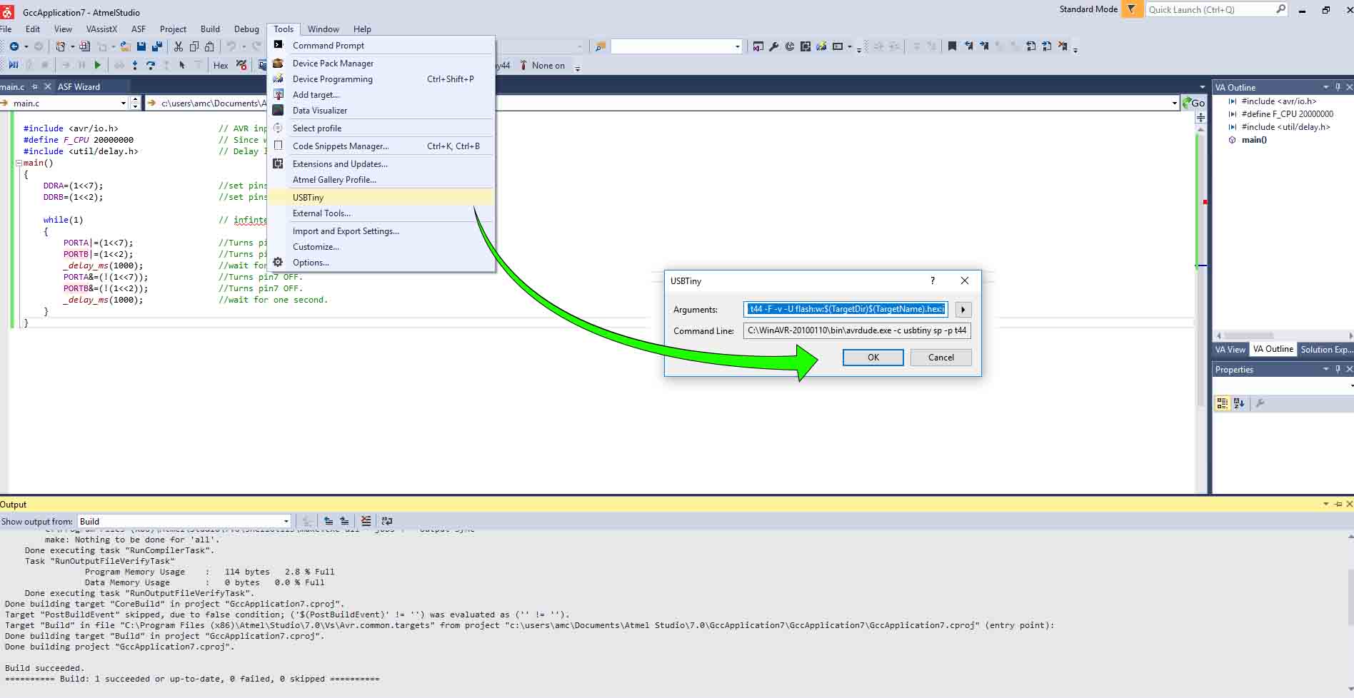
Next we have to add our programmer to our enviournment. Choose Tools -> External Tools -> Fill the spaces as shown below. Put this
-c usbtiny sp -p t44 -F -v -U flash:w:$(TargetDir)$(TargetName).hex:iin the argument space
Check wether the programmer is properly configured. Open tools and check wether our programmer is added. Just test it by uploading a simple code.
I tried a simple code to blink the LEDs in my board
Before starting the programming a little bit about the programming.
DDRx DDR stands for Data direction Register, basically it is an 8-bit register which determines whether one pin will be an input or output pin. If you want the pin you connected the LED to be set as output then you should give that value of that as 1 on DDRx. Example I connected my LED to PA7, hence I have to make it as out put in DDRA.Hence I give the code to set the pin PA7 as out put by writing. DDRA=0xff; This is HEX equivalent for DDRA=ob11111111 What this does is that it will set all the pins on the PA7 as output pins.
PORTxwhile DDRx denotes the direction of the Pin, PORT denotes the state of it. That means if I give a value 1 in the PORT register of that pin It would be set to HIGH, or 5V in case of the micro controller.
PINxregister is a dynamic register whose value will be automatically updated based on the received values of the sate of all pins, so 5V to that pin will write 1 to that register.
ow lets start programming .To build the code just click build -> Build Solution or press "F7"
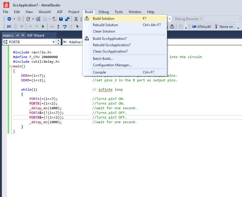
AVR code
                                    #include <avr/io.h>                    // AVR input/output library
                                    #define F_CPU 20000000                 // Since we connected a 20MHz crystal into the circuit
                                    #include <util/delay.h>                // Delay library
                                    int main()
                                    {
                                      DDRA|=(1<<2);                       //set pins 2 in the A port as output pins.
                                      DDRB&=(~(1<<2));                    //set pins 2 in the B port as input pins.
                                      while(1)                           // infinte loop

                                      {
                                        if(!(PINB&(1<<2))){
                                          PORTA|=(1<<2);                 //Turns pin2 ON.
                                        }
                                        else{
                                          PORTA&=(~(1<<2));              //Turns pin2 OFF.
                                        }
                                      }
                                    }
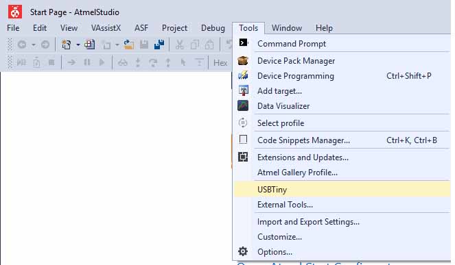
Upload to the Chip using the programmer .Choose Tools -> USBTiny -> OK
This video shows the result.
Experiment with other architectures
In this week group assignment is to try out some other acchtecture other than AVR microcontrollers.
ARM (Advanced RISC Machines)
There would be a very small segment of the mobile community that would not have heard anything about the Android OS by Google. This OS seems to be giving many proprietary vendors a run for their money and the owners many a sleepless nights. But did you know as to what does android depend on for its good performance apart from its robust code? What makes it run so smooth and yet amazingly fast without costing you a fortune? What drives the Android? The answer is ARMs, Advanced RISC Machines, previously known as Acorn RISC Machines.
ARM machines have a 32 bit Reduced Instruction Set Computer (RISC) Load Store Architecture. (Also read article on CISC & RISC Architecture) The relative simplicity of ARM machines for low power applications like mobile, embedded and microcontroller applications and small microprocessors make them a lucrative choice for the manufacturers to bank on. The direct manipulation of memory isn’t possible in this architecture and is done through the use of registers. The instruction set offers many conditional and other varieties of operations with the primary focus being on reducing the number of cycles per instruction featuring mostly single cycle operations.
All instructions in the ARM ISA are conditional with the normal execution instructions also being accompanied by condition AL. There are 14 conditions available excluding AL. The instruction set added many feathers to its cap as and when the generations grew. The transistor count has also increased substantially from 30000 in ARM2 to about 26 million in Cortex-A9 ARM. An additional Thumb architecture was developed to support 16-bit instruction models on the otherwise 32 bit ARM machines. No matter the added advantage of increased code density which was about 65% of the original ARM code, this resulted in a little performance drop in the ARM machines. This drop was somewhat balanced with Thumb 2 which was a major extension over the Thumb ISA.
ARM Architecture Contd.
In Thumb 2, the compiler automatically selects a mixture of 16 bit and 32 bit instructions. It is to be noted that only the instruction set changes from 32 bit to 16 bit, the core continues to operate at 32 bit. The evolution of ARM v7 cores saw the development of Thumb Execution Environment (Thumb-EE) which offered dynamic coding by compiling the code moments before or during execution itself. Thumb feature is basically another Instruction Set running on the same platform. Another Instruction set, to execute Java codes on ARMs was developed soon and was named Jazelle. These three Instruction sets are now the three states on an ARM core and to shift from one state to another, directives like ARM, THUMBX and THUMB are given to the assembler. The evolution of ARM architectures is shown in the figure below:
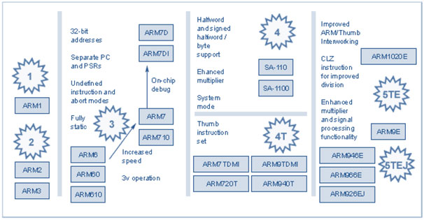
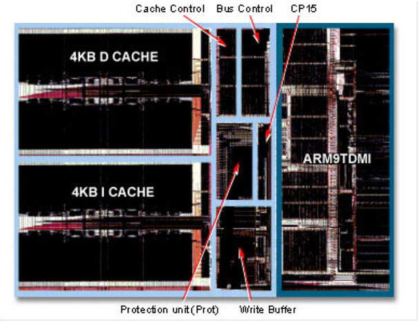
The nomenclature of ARMs is based on the type and features used in it. For example in ARM7TDMI, ‘T‘ stands for Thumb, ‘D’ and ‘I’ together comprise the on chip debugging facilities and ‘M’ signifies support for an enhanced multiplier and support for 64-bit results. ARMx7z like the ARM1176JZ-S indicates AXI bus, physically mapped caches and MMU, has version 6Z architecture. In this way, there is a naming convention for ARM devices. ARM architectures used various stages of pipelining to enhance the flow of instructions to the processors. This allows several operations to be performed simultaneously which would otherwise be performed serially. For example, the ARM7TDMI used 3 stages, ARM9TDMI uses 5 stages and the ARM10TDMI use 6 stages of pipeline to speed up delivery and faster clocking. Cores up to ARM7 followed a Von Neumann type architecture which is essentially memory mapped architecture. ARM9 and its successors shifted to Harvard Architecture which is port mapped. They also provide a robust debugging environment like the Embedded ICE Logic which connects with the external world through a Test Access Port or a standard IEEE 1149.1 JTAG connection. This helps shorten the development cycle.
ARM Registers
n general ARMs have 37 registers arranged in partially overlapping banks, with separate register banks for each processor mode thus providing rapid context switching for special operations. The various modes in an ARM can be summarized in the figure below.
Each register is 32 bits in size. The registers are roughly divided into:
- 30 General Purpose Registers: Only 15 GPRs are visible any one time depending on the mode of operation and are numbered R0-R12, Stack Pointer and Link Register. While the stack pointer is essentially used by the compliers like those of C/C++, its use as any other GPR is deprecated. Link register stores return addresses in subroutines or exceptions depending on the mode of operation.
- Program Counter: Loads the address of destinations on branching operations and may be manually set while doing subroutine calls.
- Application Program Status Register: It contains a copy of flags from the ALU to check if the conditional instructions were executed.
- Current Program Status Register: It holds various information regarding APSR, current processor mode, interrupt flags, execution state bits etc.
- Saved Program Status Register: In case an exception is detected, this register holds the values of the CPSR.
Classification of Instruction Set
The ARM and Thumb instruction sets can be broadly classified into the following functional groups.
- Branching and Control Instructions: Instructions like subroutine calls, looping and changing the state between ARM and Thumb fall under this category of instructions.
- Register Load and Store instructions: Loading the values of single registers to and from the memory are covered under this type of instructions. The values may be 32 bit word, a 16-bit half word or an 8 bit unsigned value.
- Multiple Register Load and Store Instructions: Facilitate the to and fro movement between the contents of the multiple registers, used in block operations and stack operations.
- Data Processing Instructions: Operations like addition, subtraction or bitwise logic on the contents of the registers are performed by this type of instructions.
- Status Register access Instructions: These instructions primarily move the contents between the status registers and the GPRs.
- Coprocessor Instructions: These provide a general framework to extend the ARM architectures.
Source:https://www.engineersgarage.com/articles/arm-advanced-risc-machines-processors
STM32
STM32 is a family of 32-bit microcontroller integrated circuits by STMicroelectronics. The STM32 chips are grouped into related series that are based around the same 32-bit ARM processor core, such as the Cortex-M7F, Cortex-M4F, Cortex-M3, Cortex-M0+, or Cortex-M0. Internally, each microcontroller consists of the processor core, static RAM memory, flash memory, debugging interface, and various peripherals.
In here Fablab Kochi we have the STM32F401 series Nucleo development boards.it's a part of the STM32 Dynamic Efficiency™ device range. These devices offer the best balance of dynamic power consumption (in run mode) and processing performance, while integrating a high number of added-value features in packages as small as 3 x 3 mm. The MCUs deliver the performance of Cortex®-M4 core with floating point unit, running at 84 MHz, while achieving outstandingly low power consumption values in run and stop modes.
- Performance: At 84 MHz, the STM32F401 delivers 105 DMIPS/285 CoreMark performance executing from Flash memory, with 0-wait states using ST’s ART Accelerator. The DSP instructions and the floating point unit enlarge the range of addressable applications.
- Power efficiency:ST’s 90 nm process, ART Accelerator and the dynamic power scaling enables the current consumption in run mode and executing from Flash memory to be as low as 128 µA/MHz. In Stop mode, the power consumption can be as low as 9 µA.
- Integration :The STM32F401 portfolio provides from 128 to 512 Kbytes of Flash, 96 Kbytes of SRAM. The available packages range from 49 to 100 pins.
download datasheet hear