
Electronics Design
So it's the 7th week since I begin my fab journey. In this week, I got following assignments,
- Redraw the echo hello-world board
- add (at least) a button and LED (with current-limiting resistor)
- check the design rules, make it (if you have time this week, test it).
A piece of circute execute tasks depending on your command is an interesting phenomenon. I have been facinated about Microcontrollers and electronic circuites from my early ages onwards. I also worked on some developmet boards like arduino, raspberry pi, nodemcu, esp8266 etc. And i also have 2yr experience in Embedded Systems. I also familier with PCB designing.
Basic Electronics
Pull-Up resistors
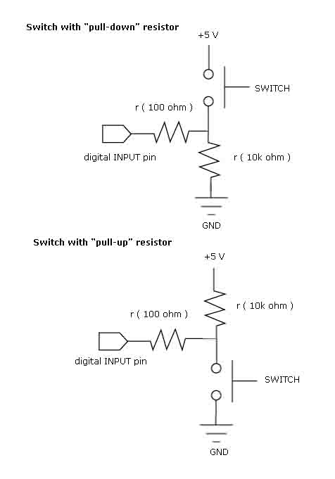
Pull-up resistors are used in electronic logic circuits to ensure that inputs to the Microcontroler settle at expected logic levels if external devices are disconnected or high-impedance. 'Just because you have nothing at all connected to an input pin doesn't mean it is a logical one.'
A pull-up resistor weakly "pulls" the voltage of the wire it is connected to towards its voltage source level when the other components on the line are inactive. When the switch on the line is open, it is high-impedance and acts like it is disconnected. Since the other components act as though they are disconnected, the circuit acts as though it is disconnected, and the pull-up resistor brings the wire up to the high logic level. When another component on the line goes active, it will override the high logic level set by the pull-up resistor. The pull-up resistor assures that the wire is at a defined logic level even if no active devices are connected to it.
A pull-down resistor works in the same way but is connected to ground. It holds the logic signal near zero volts when no other active device is connected.The value of a pull down or pull up resistor will vary depending upon your specific devices involved.
LED series Resistor value
A light-emitting diode (LED) is a two-lead semiconductor light source. It is a p–n junction diode that emits light when activated.If we apply a current that is greater than the desired value of an led the junction temperature will increace because Heat = I^2 x R x t ,(I = current through Led,R = Resistance of conductor,t = time ) .So if the junction temperature increas it may lead to the fast deterioration of the juction or complete breakdown of the device so it is importent to maintain the current through the led . the easiest and simplest way is to use a series resistor.
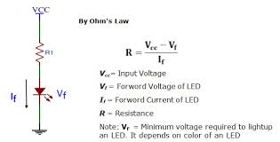
The above figure is a typical led connection where .Rs is the Series resistance ,Vs is the source
voltage,Vf is the forward voltage of the LED(also referred to as the "voltage drop") ,If is the
safe current through the LED
So we have
Vcc = supply voltage =5v
Vf = 1.8V
If = 18mA
So R = (5 - 1.8)/(.018) = 177.77
The closest resistor having a greator value than this in our lab is 499 ohm . I hope may be this
work with a reduced brightnes.
PCB Designing
Proteus 8.0
Proteus combines ease of use with powerful features to help you design, test and layout professional PCBs like never before. With nearly 800 microcontroller variants ready for simulation straight from the schematic, one of the most intuitive professional PCB layout packages on the market and a world class shape based autorouter included as standard, Proteus Design Suite 8 delivers the complete software package for today and tomorrow's engineers.

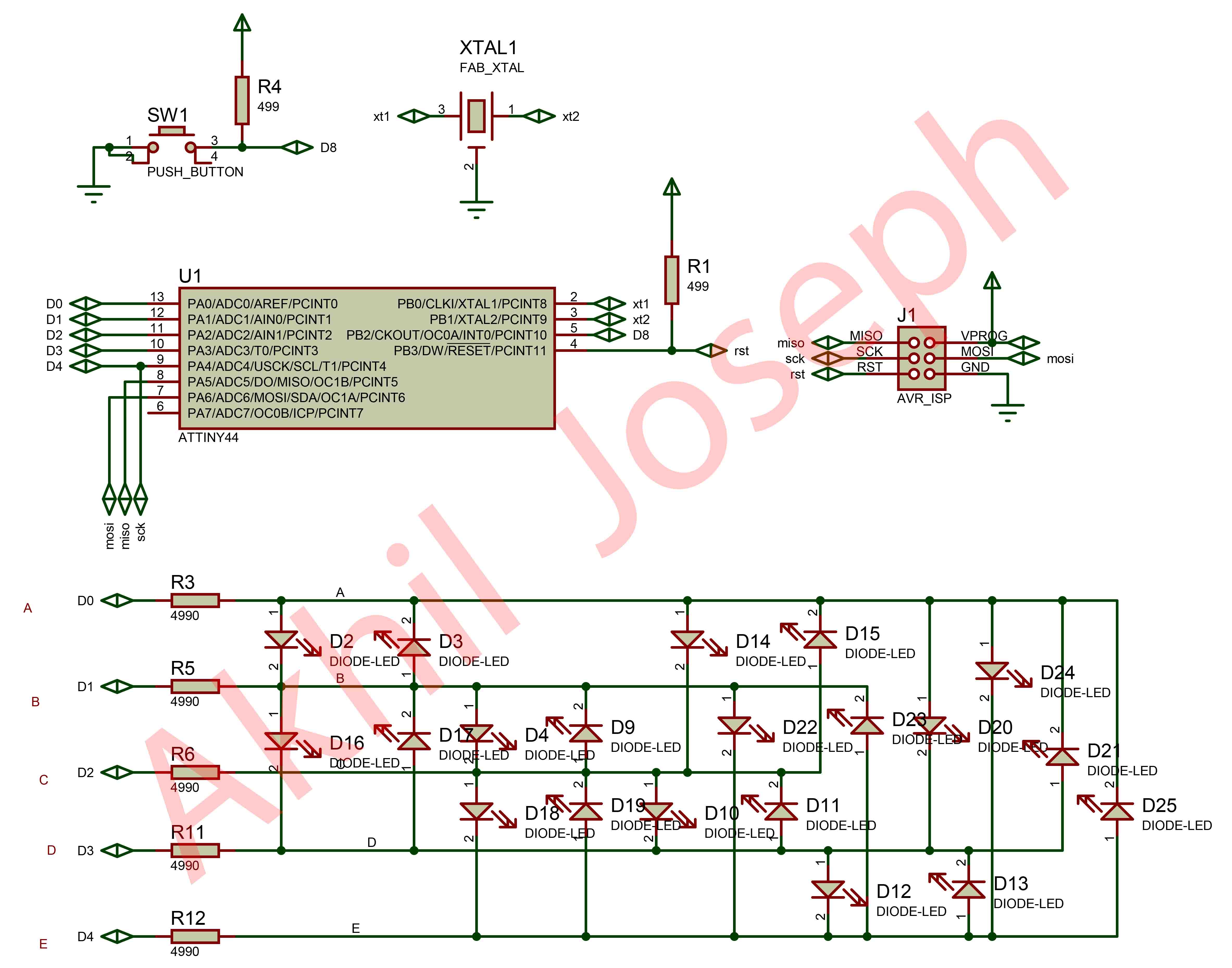
Schematics
I use 5 pin to drive 20 LED. A technique called charliplexing to do this.
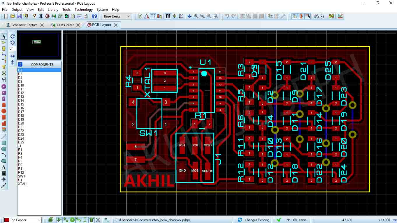
LAYOUT
In this section, the PCB routing is make, where tracks nedded.
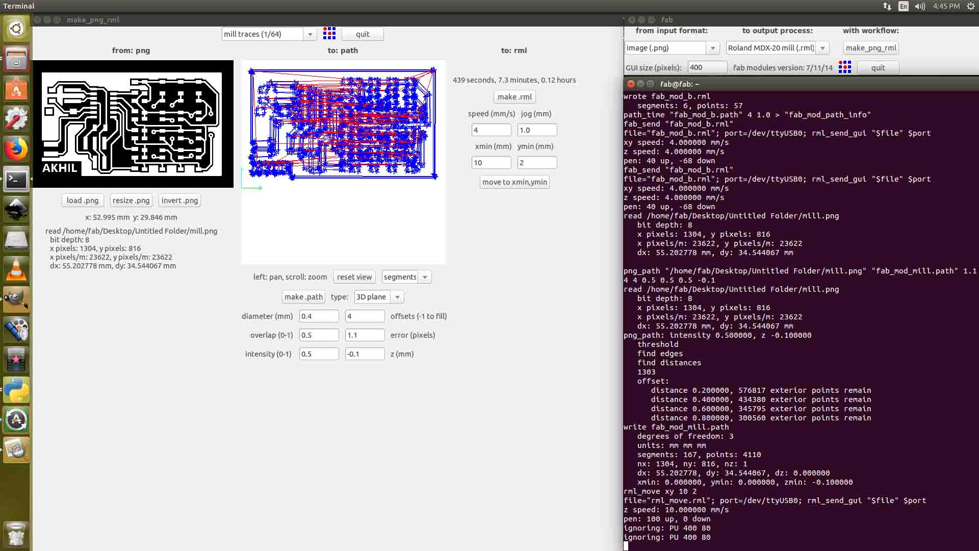
PCB Milling
After Design, i export PNG to mill PCB
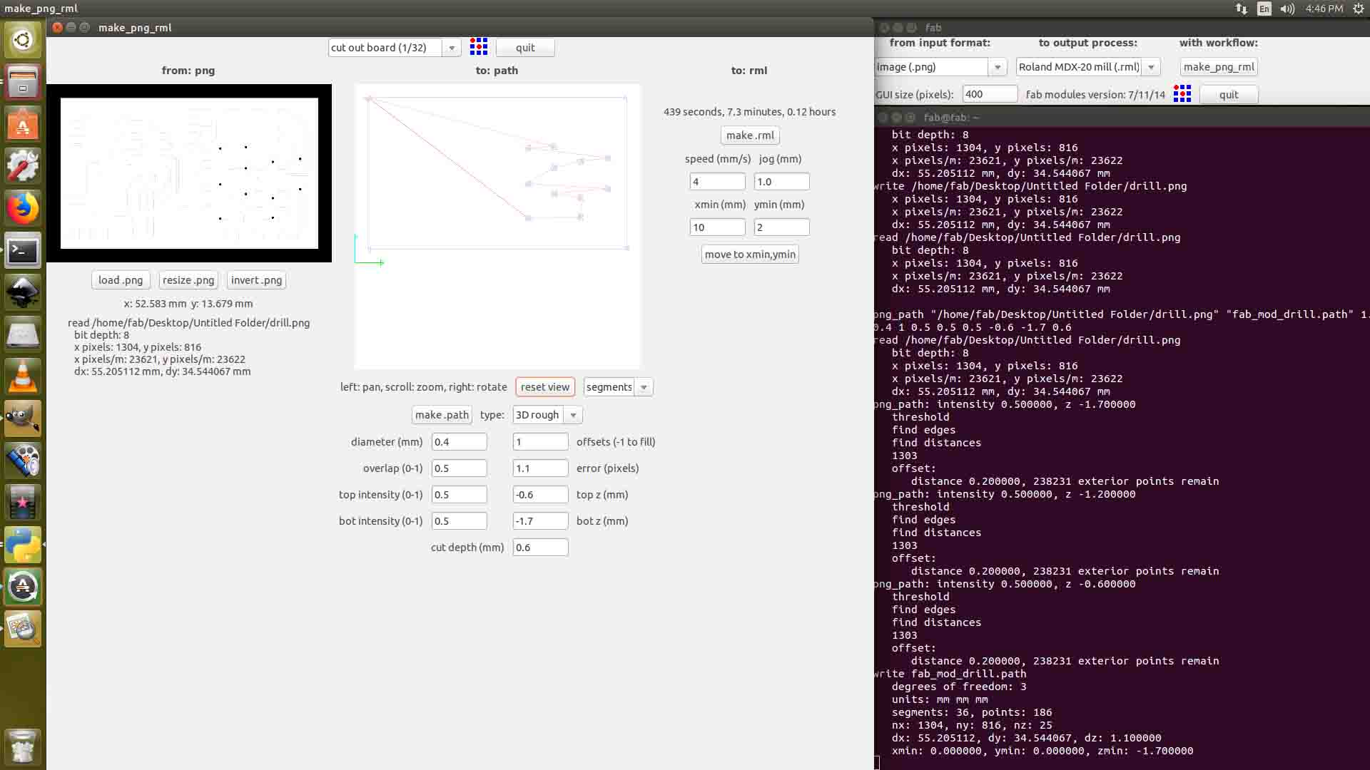
Drilling
This circuit have some jumpers, so i use through hole via technoiqe to make it as beautiful, so the After milling i drill PCB with Cutting bit
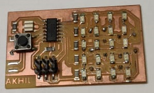
Soldering
After soldering i got this board
Programing and Testing
I program my board using arduino ide full source attached below
  #define A 0
  #define B 1
  #define C 2
  #define D 3
  #define E 4
  #define DELAY 500
  int c[5][4][2] =
  {
    { {A, E}, {B, E}, {C, E}, {D, E} },
    { {A, D}, {B, D}, {E, D}, {C, D} },
    { {E, C}, {A, C}, {D, C}, {B, C} },
    { {E, B}, {D, B}, {C, B}, {A, B} },
    { {E, A}, {D, A}, {C, A}, {B, A} }
  };

  int frames[][5] =
  {
    { 0b0101,
      0b0101,
      0b0111,
      0b0101,
      0b0101
    },
    { 0b0111,
      0b0100,
      0b0111,
      0b0100,
      0b0111
    },
    { 0b0100,
      0b0100,
      0b0100,
      0b0100,
      0b0111
    },
    { 0b0111,
      0b0101,
      0b0101,
      0b0101,
      0b0111
    }
  };
  void setup()
  {
    pinMode( A, INPUT );
    pinMode( B, INPUT );
    pinMode( C, INPUT );
    pinMode( D, INPUT );
    pinMode( E, INPUT );
    test_loop();
  }
  void setup2()
  {
    pinMode( A, INPUT );
    pinMode( B, INPUT );
    pinMode( C, INPUT );
    pinMode( D, INPUT );
    pinMode( E, INPUT );
  }
  void display( int frame[5], int duration )
  {
   int times = 0;
   int x = 0;
   int y = 0;
   while( times < duration )
    {
      for( y = 0; y < 5; y++ )
      {
        for( x = 0; x < 4; x++ )
        {
        setup2();
        if( frame[y] & (0b100 >> x) )
        {
          light( c[y][x] );
          delayMicroseconds(DELAY);
          times++;
        }
      }
     }
    }
  }
  void light( int pins[2] )
  {
    pinMode( pins[0], OUTPUT );
    digitalWrite( pins[0], HIGH );

    pinMode( pins[1], OUTPUT );
    digitalWrite( pins[1], LOW );
  }
  void test( int pins[2] )
  {
    setup2();
    light(pins);
    delay(50);
  }
  void test_loop()
  {
    test(c[0][0]);
    test(c[0][1]);
    test(c[0][2]);
    test(c[0][3]);
    test(c[1][0]);
    test(c[1][1]);
    test(c[1][2]);
    test(c[1][3]);
    test(c[2][0]);
    test(c[2][1]);
    test(c[2][2]);
    test(c[2][3]);
    test(c[3][0]);
    test(c[3][1]);
    test(c[3][2]);
    test(c[3][3]);
    test(c[4][0]);
    test(c[4][1]);
    test(c[4][2]);
    test(c[4][3]);
  }
  void loop()
  {
    test_loop();
  }
My Board says "HELLO"

Somthing INTERESTING..!!
Group Assignment
This week's assignment was to use the test equipment in your lab to observe the operation. So let's meet with the electronics equipments
Multimeter
A multimeter is a tool for testing different parameters of an electronic circuit board.In our lab, we use UNI-T UT61A multimeter. You can download the user's manual from Here
Tests can be done using Multimeter
- AC Voltage
- DC Voltage
- AC Current
- DC Current
- continuity
- Resistance
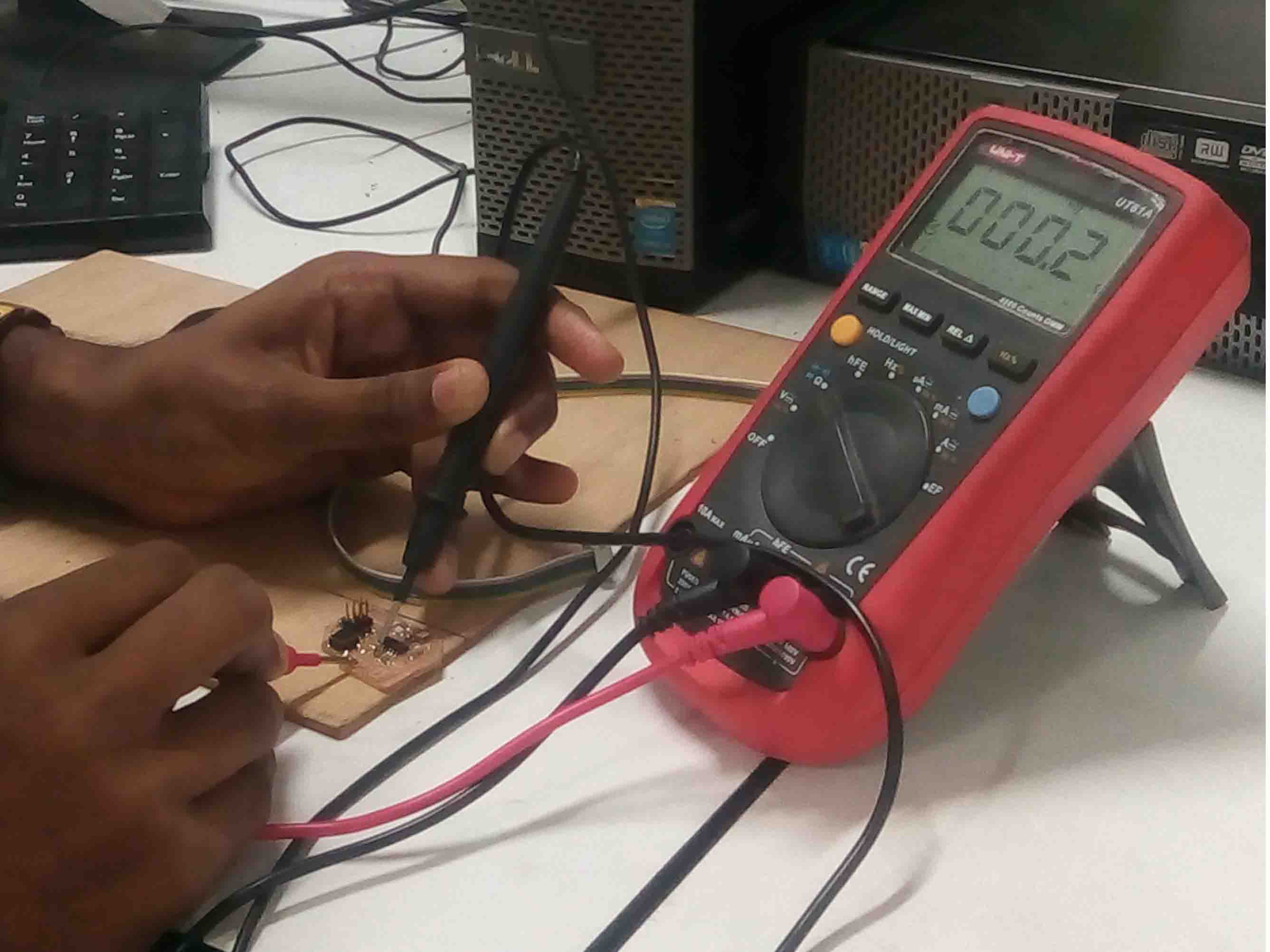
We used multimeter for testing continuity in Jofin's PCB
DC Power Supply
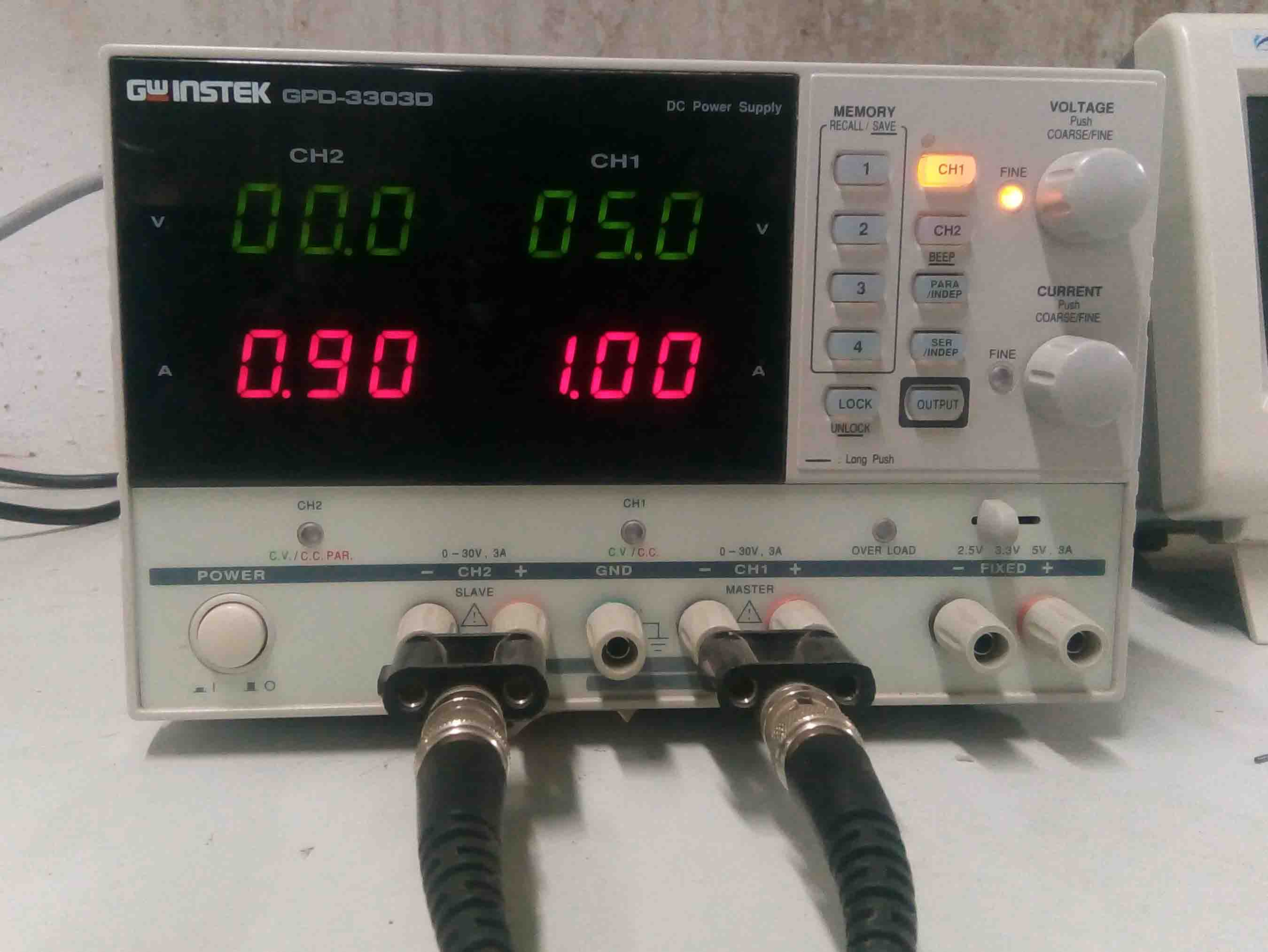
In falab kochi we use Gw instek GPD-3303D. You can download the user's manual Here
- 2/3/4 Independent Isolated Output
- 4 LED Display Sets: 3 digits after decimal point
- Minimum Resolution :1mV/1mA(GPD-2303D/GPD-3303S/GPD-4303S)
- 100mV/10mA(GPD-3303D)
- Digital panel control(rotary encoder Switch, rubber key with indicator)
- User-friendly operation, coarse/fine volume control
- 4 Sets Save/Recall
- Key-Lock
- Output on/off
- Tracking Series and Parallel mod
- Smart cooling fan achieving low noise
- USB Standard Interface
- PC Software & USB Driver
- Labview driver
Digital Oscilloscope
In falab kochi we use UNI DSO-1100. You can download the datasheet Here
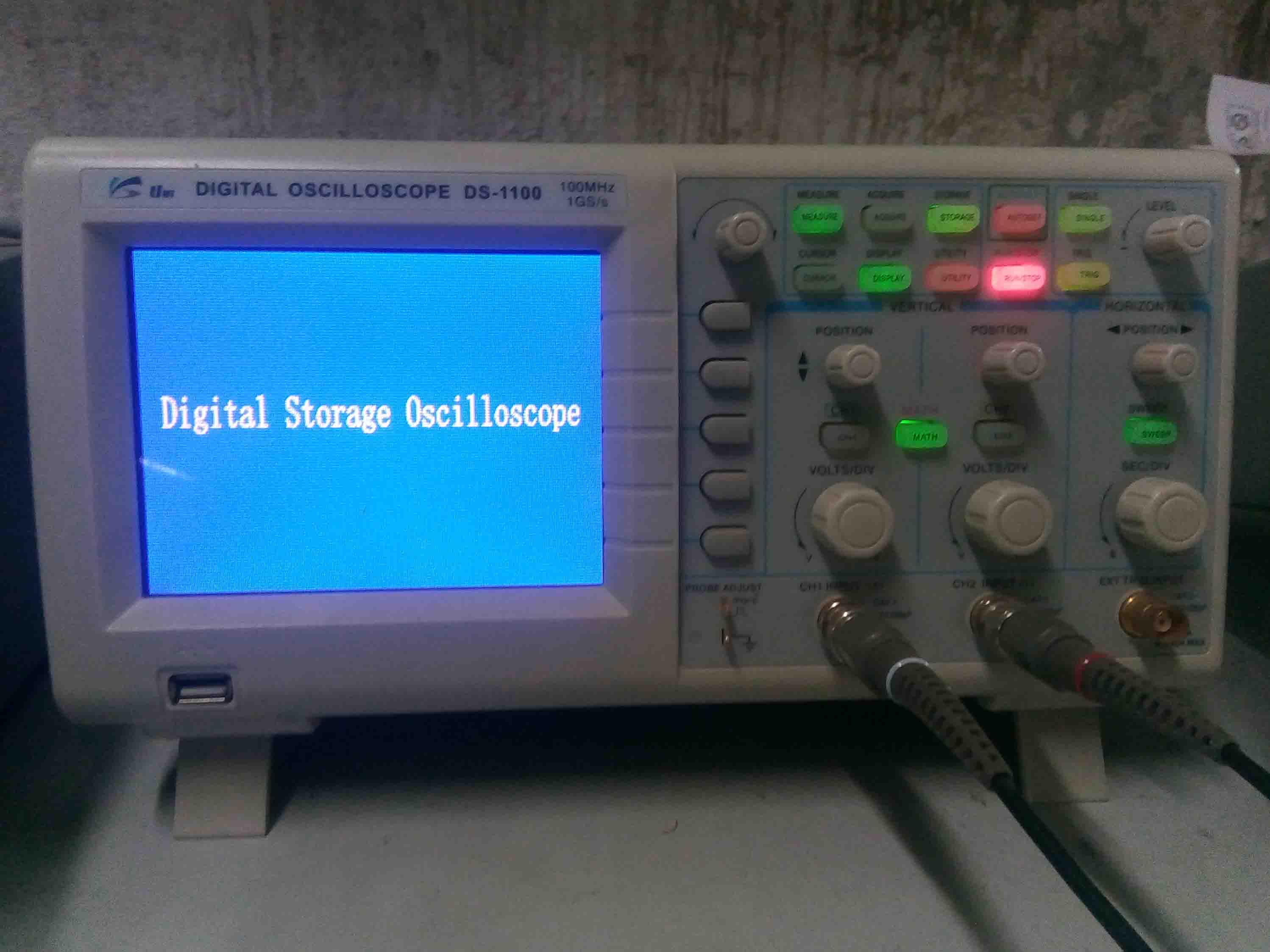
Features
- 100 MHz bandwidth, 1 M Memory
- High resolution color LCD display
- USB storage, RS232C & J45 interface
- 4000 point record length for each channel
- Multi-waveforms math, FFT Function
- Built-in delay sweep function
- Automatic Multi-waveform Measurement
- Cursor & Track measurement
- Waveform Record & Recall, Trigger Mode for Edge, Video, Pulse Width, Slope & Alternate
- Display of date, clock and help information
Function Generator
In falab kochi we use GW Instek AFG-2125 . You can download the datasheet Here
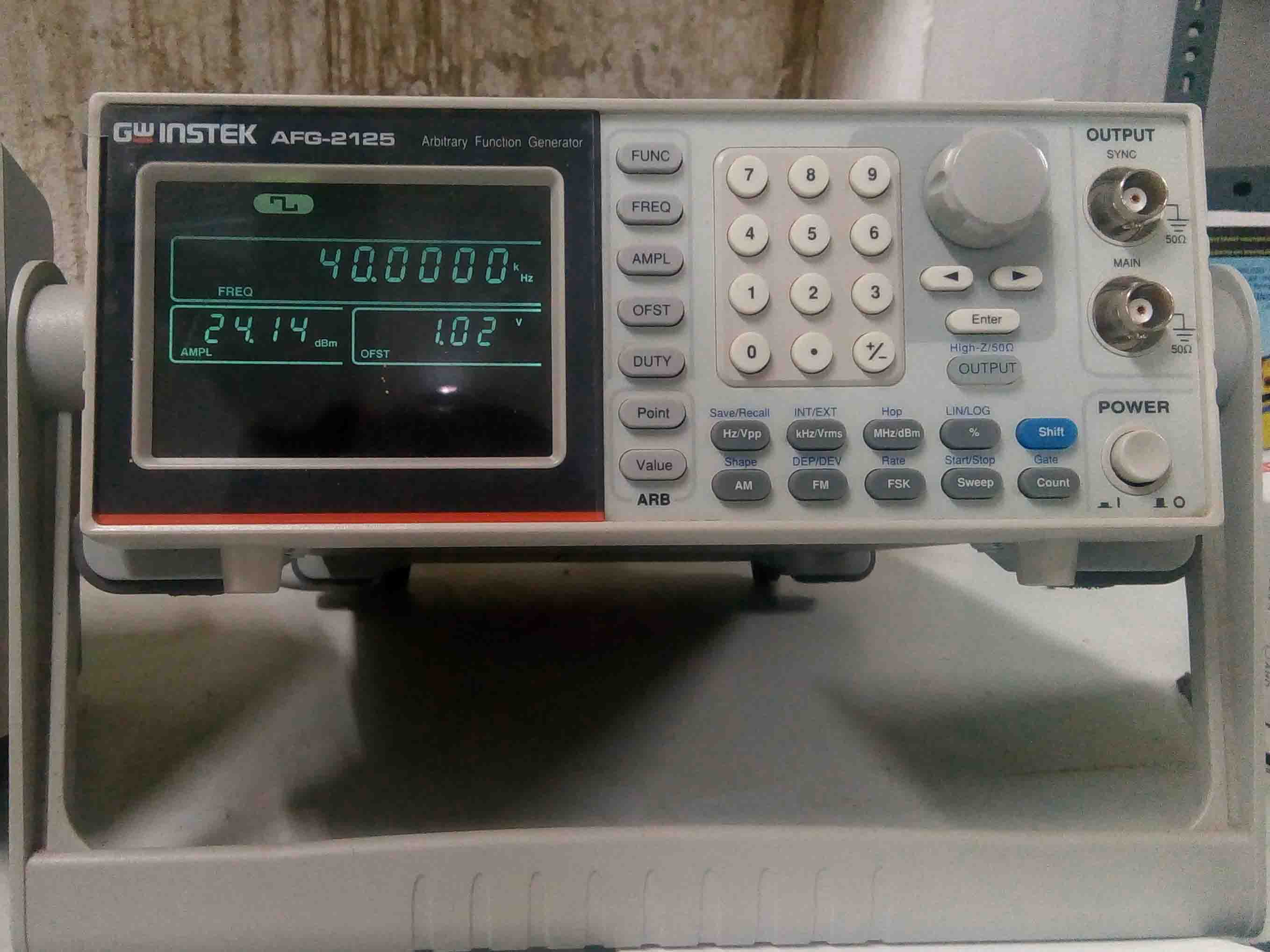
Features
- 0.1Hz to 25MHz with in 0.1Hz Resolution
- Sine, Square, Triangular, Noise and Arbitrary Waveform
- 20MSa/s Sampling Rate, 10 bit Vertical Resolution and 4k Point Memory for Arbitrary Waveform
- 1% ~ 99% adjustable duty cycle for Square Waveform
- Waveform Parameter Setting Through Numeric Keypad Entry & Knob Selection
- Amplitude, DC Offset and Other Key Setting Information Shown on the 3.5" LCD Screen Simultaneously
- AM/FM/FSK Modulation, Sweep, and Frequency Counter Functions (AFG-2100 only)
- USB Device Interface for Remote Control and Waveform Editing
- PC Arbitrary Waveform Editing Software