3d scanning and printing
So it's the 6th week since I begin my fab journey. In this week, I got following assignments,
- design and 3D print an object (small, few cm)that could not be made subtractively
- 3D scan an object (and optionally print it)
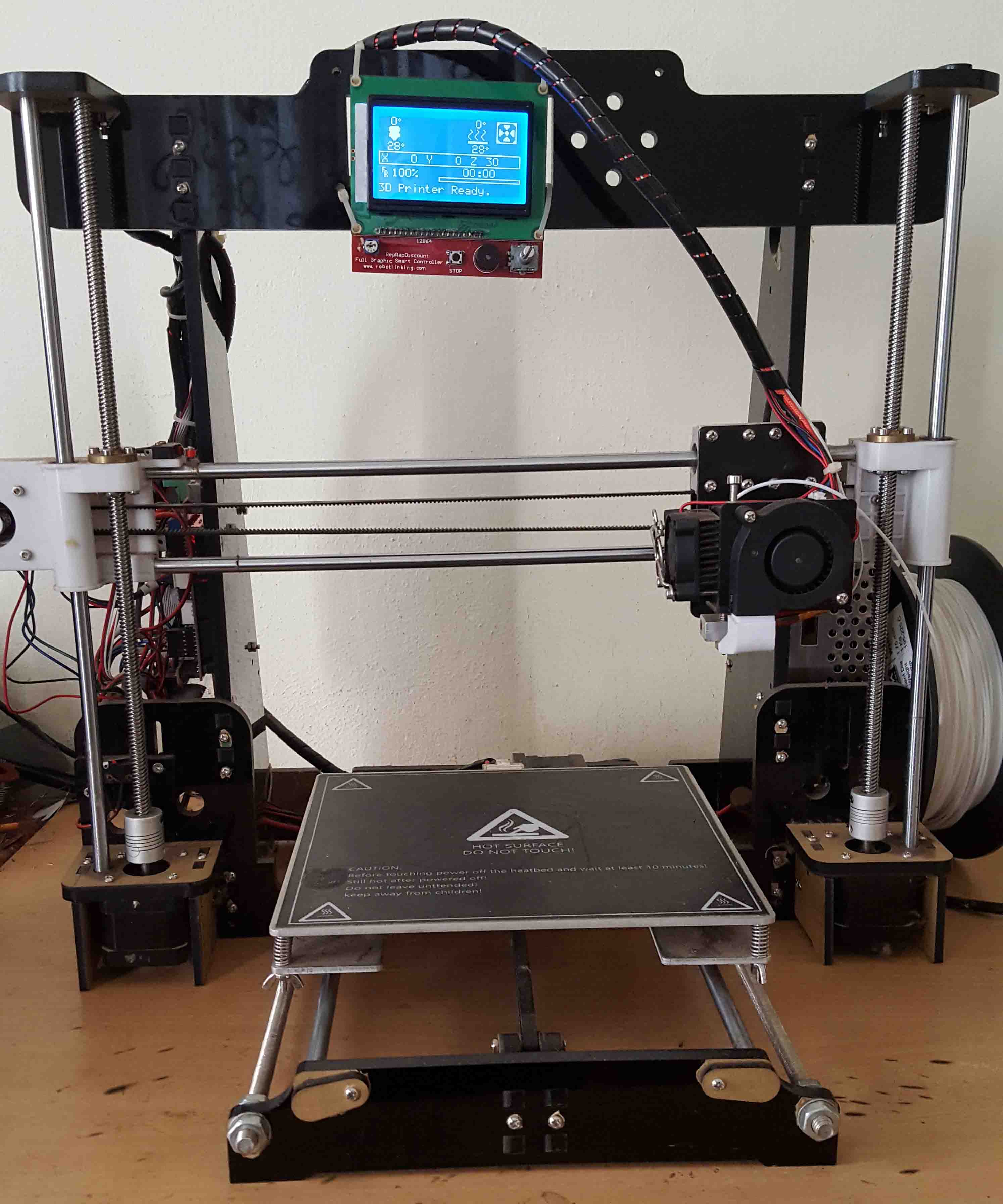
In my collage project, I use Pursa i3 standard design. Which have following features.
- HOT bed
- 210x210x180
- 1.75mm Filament
- Ramps 1.4
- Arduino Mega
- Full Graphics display
- up to 20 microns
- Operating nozzle temperature 180°C - 260°C
- Operating heated bed temperature 50°C – 140°C
- Fused Filament Fabrication (FFF)
I just stopped the printer development after my project presentation. After 1 year one of my client YESCOLLAGES Infotech Pvt Ltd intrested in 3D-printers. So that i jst reopen the development in that time i add some new features.
- Auto bed leveling
- Integration to CURA
- Octoprint server (Network print Wi-fi/Ethernet)
- Web streeming
Currently I sell my printers to Yescolages and they sell it to their clients such as Engineering collages, architectures..etc
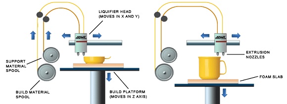
Fused-deposition molding (FDM)
Fused deposition modeling (FDM) technology was developed and implemented at first time by Scott Crump, Stratasys Ltd. founder, in 1980s. Other 3D printing companies have adopted similar technologies but under different names. A well-known nowadays company MakerBot coined a nearly identical technology known as Fused Filament Fabrication (FFF). With help of FDM you can print not only functional prototypes, but also concept models and final end-use products. What is good about this technology that all parts printed with FDM can go in high-performance and engineering-grade thermoplastic, which is very beneficial for mechanic engineers and manufactures. FDM is the only 3D printing technology that builds parts with production-grade thermoplastics, so things printed are of excellent mechanical, thermal and chemical qualities.
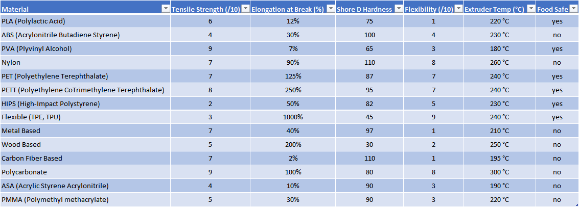
Printing materials
The material used will affect the mechanical properties and accuracy of the printed part, but also its price.Table of materials used in an FDM printer is given below:
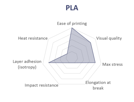
PLA
PLA is the easiest polymer to print and provides good visual quality. It is very rigid and actually quite strong, but is very brittle.
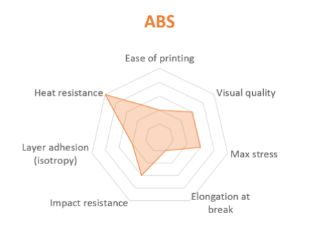
ABS
ABS is usually picked over PLA when higher temperature resistance and higher toughness is required.
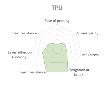
TPU
TPU is mostly used for flexible applications, but its very high impact resistance can open for other applications.
Group Assignment
Design Rules
Introduction
Different 3D printing processes have different capabilities and different design restrictions. In this article we will talk about key design considerations that apply to all 3D printing processes.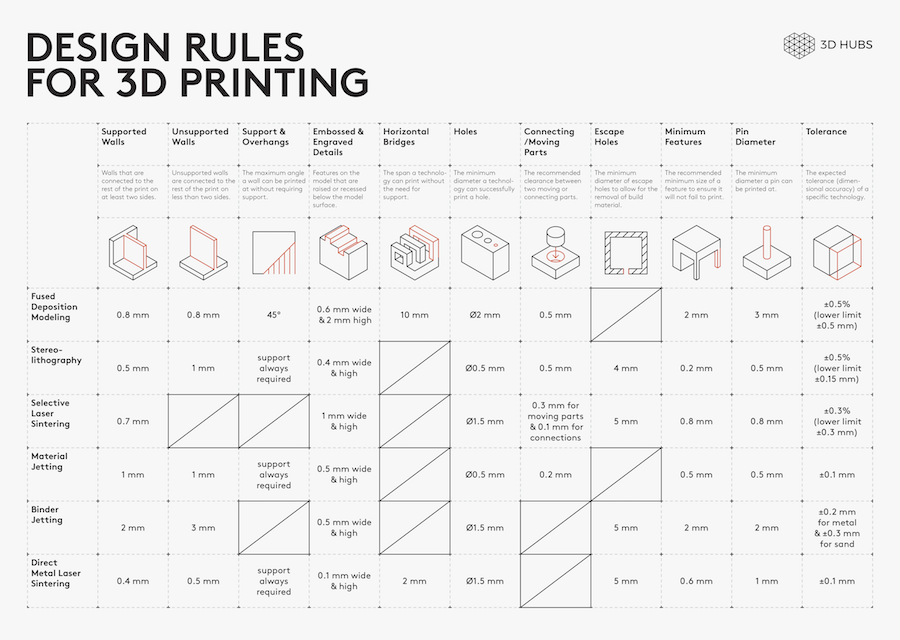
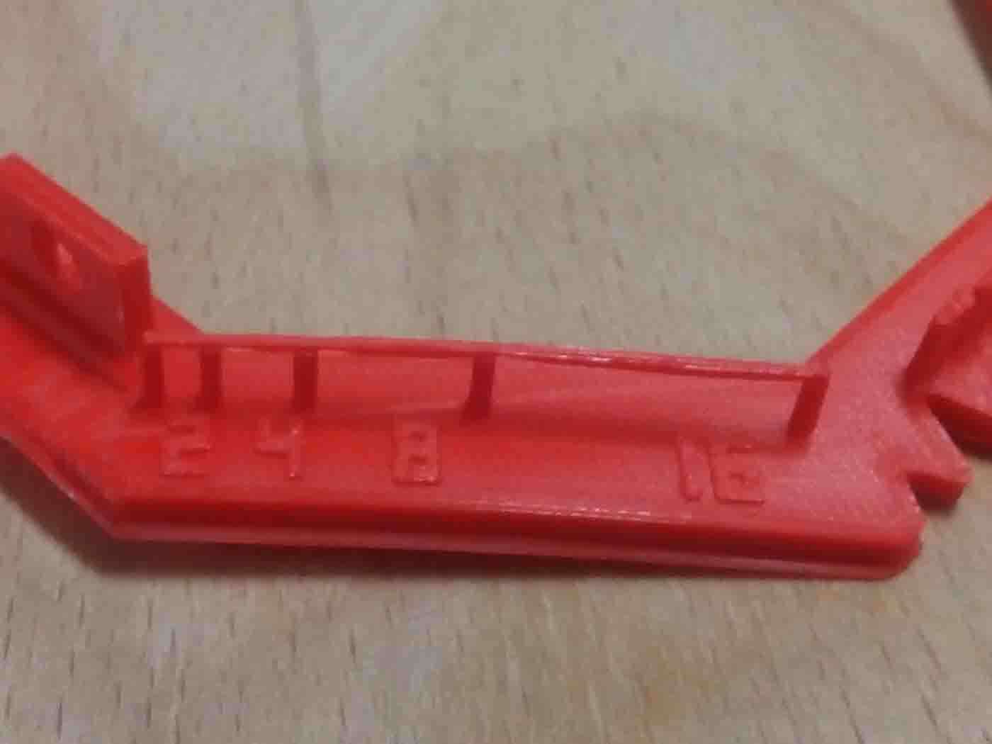
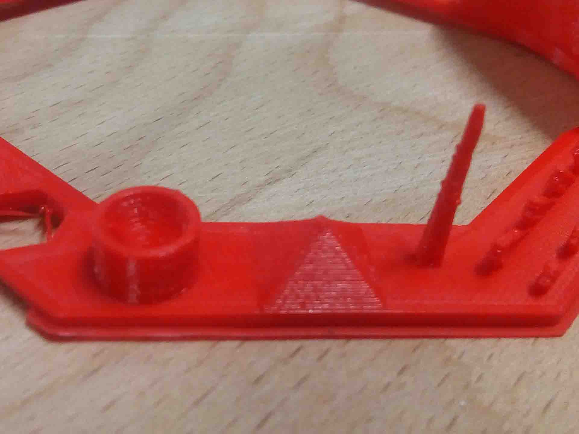
I got a set of tests for checking the design rules. Luckly I find a full set of test from Thingverse
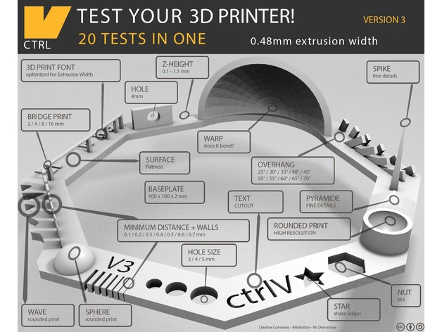
We had help from the thingverse file. So we set the parameters according to it. We set the printing settings as below:
| Rafts: | Supports: | Resolution: | Infill: |
|---|---|---|---|
| - Yes | - No | -0.1mm or higher | 30% |
Parameters:
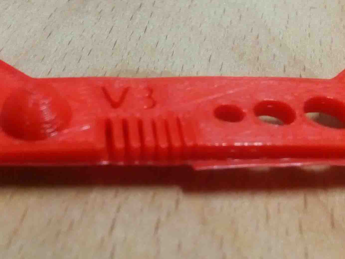
- Nut, Size M4 Nut should fit perfectly
- Wave, rounded print
- Star, Sharp Edges
- Name, Complex Shapes
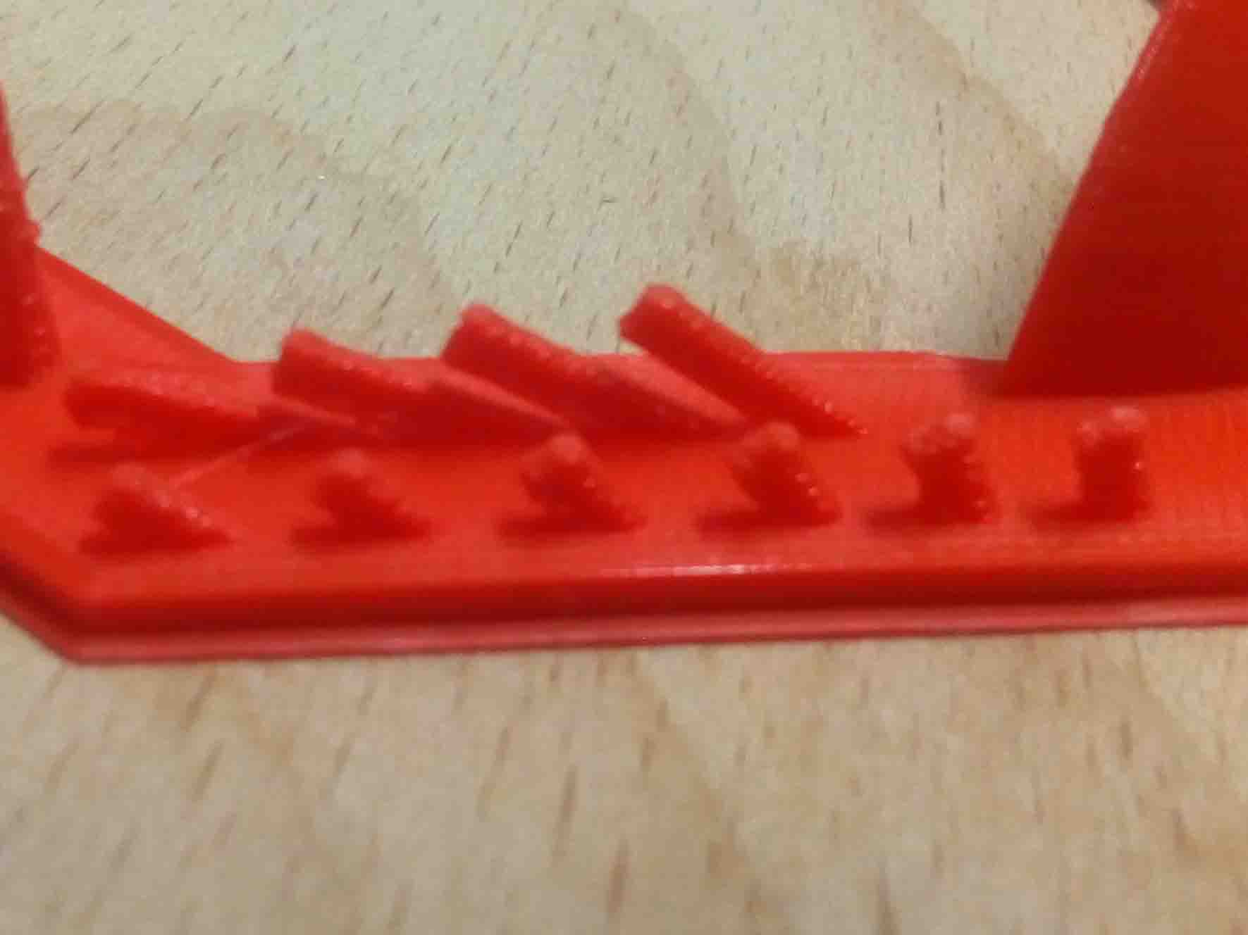
- Holes, Size 3, 4, 5 mm
- minimal Distance: 0.1, 0.2, 0.3, 0.4, 0.5, 0.6, 0.7 mm
- Z height: 0.1, 0.2, 0.3, 0.4, 0.5, 0.6, 0.7, 0.8, 0.9, 1.0, 1.1 mm
- Wall Thickness: 0.1, 0.2, 0.3, 0.4, 0.5, 0.6, 0.7 mm
- Bridge Print: 2, 4, 8, 16 mm
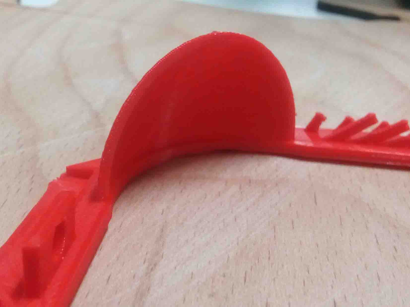
- Sphere, Rounded Print 4.8mm height
- Sphere Mix, 7 mm height
- Pyramide, 7 mm height
- Overhang: 25, 30, 35, 40, 45, 50, 55, 60, 65, 70°
- Warp, does it bend?
- 3D Print Font, optimized for 3D printing
- Surface, Flatness
- Size, 100 x 100mm x 23.83 (10mm width)
- Spike, minimum Layer Time, 21 mm height from Bottom (include Baseplate)
- Hole in Wall, 4 mm diameter, check for proper print
- Raft Test, raft should be just under the model
- Retract Travel, check retract settings for longer travel
We follow the instructions and put it to print
Digital vs. Physical
The most important thing to remember while designing for 3D printing is the fact that your digital design will become a physical object. In the digital design environment, there are no laws of physics to adhere to, such as gravity. Each 3D printing process has its own limitations. Here are the most important design considerations that apply to all of them that you should keep in mind:
General Design Consideration for 3D Printing
Overhangs
All 3D printing processes build parts layer-by-layer. Material cannot be deposited onto thin air, so every layer must be printed over some underline material. Overhangs are areas of a model that are either partially supported by the layer below or not supported at all. There is a limit on the angle every printer can produce without the need of support material. For example, for FDM and SLA this angle is approximately 45o degrees. It is a good practice to limit the overhangs of a model, as layers printed over support usually have a rougher surface finish.
Also:
Wall thicknes:
The second thing to keep in mind when designing a part to be 3D printed is wall thickness. Every 3D printing process can produce accurately features that are thin up to a certain point. For example, imagine you are an engineer who designs hang gliders for a living. You have come up with a great, new design that you have decided to 3D print scaled down for testing. 3D modeling programs allow you to model the sailcloth of the wing, but you would encounter problems when you would try to 3D print it, as its thickness would be extremely small. As a good practice, always add thickness to your models. Walls with thickness greater than 0.8 mm can be printed successfully with all processes.
Warping
Something that is often easily overlooked while designing a 3D model is the fact that the materials used for 3D printing undertake physical change: they are melted, sintered or scanned with a laser and solidified. The heating and cooling of material can cause the parts to warp while printing. Large, flat surfaces can be especially prone to warping. Warping can typically be avoided by using correct machine calibration and having adequate surface adhesion between your part and the print bed. Your Hub will be able to offer more advice on design techniques that can be used to minimize the likelihood of warping. A good practice is to avoid large flat surfaces and add rounded corners to your 3D models.
Level of detail
When you are creating a 3D model with intricate details, it is important to keep in mind what is the minimum feature size each 3D printing process can produce. The minimum level of detail is connected to the capabilities and mechanics of each 3D printing process and to the selected layer height. The process and materials used will have an impact on the speed and cost of your print, so determining whether smaller details are critical to your model is an important design decision.
Source(https://www.3dhubs.com/knowledge-base/key-design-considerations-3d-printing#/process-specific-guidelines)
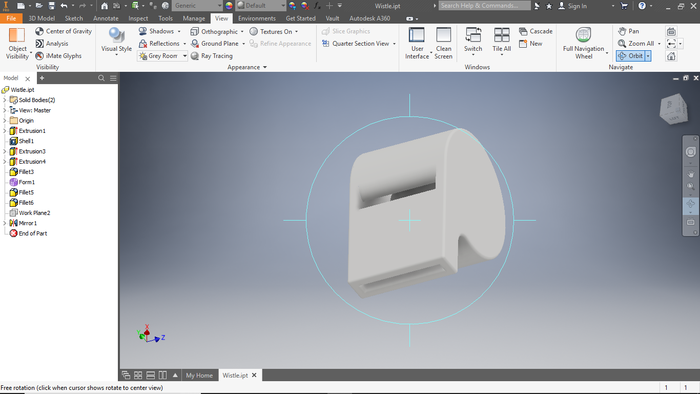
3D Designing
Assignment was Design and 3D Print that could not be made subtractively , So I have designed a Whistle In Autodesk Iventor..
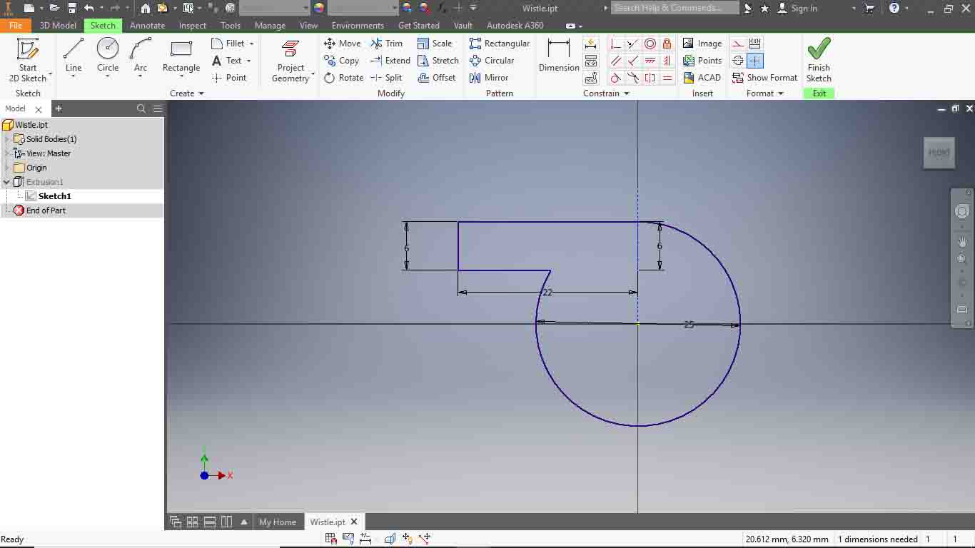
I jst draw a siimple square and a retangle.
3D-printing
slicing
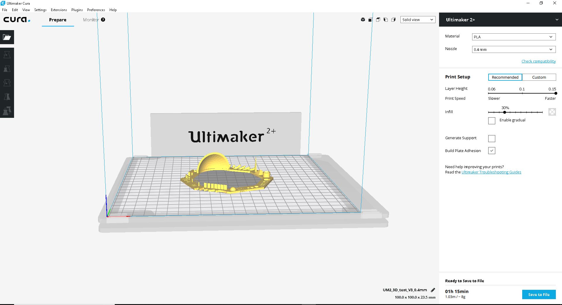
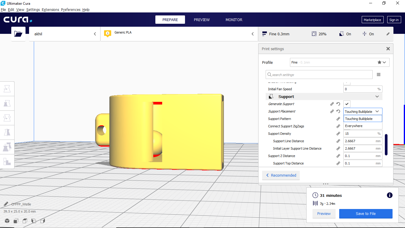
I just try to print this, I use Cura to slice the design. The 3D printer can only take G-CODE files. So we need to convert it as G-CODE. To do this, i use cura.
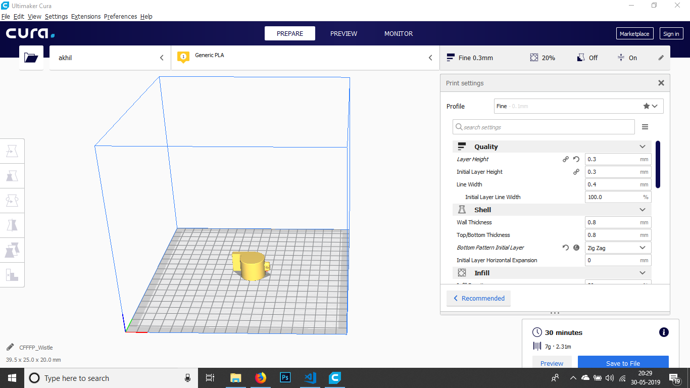
In this wee need to set some parameters.
- Meterial
- Layer Hight
- Infill
- Support
support placement in this select Touching buildplate
otherwise support will generate inside the wistle that is very fifficult to remove.
3D-printer
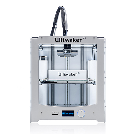
In our lab (Fablab Kochi) We have been using Ultimaker for 3D printing. It's very easy to use and very much accurate..
Download UltiMaker Usermanual
Printing procedure
So now we are going physicaly print the design using an Ultimaker 3d printer. For that we need insert the SD card into the SD card slot in the Ultimaker. You can see the details like in following display..
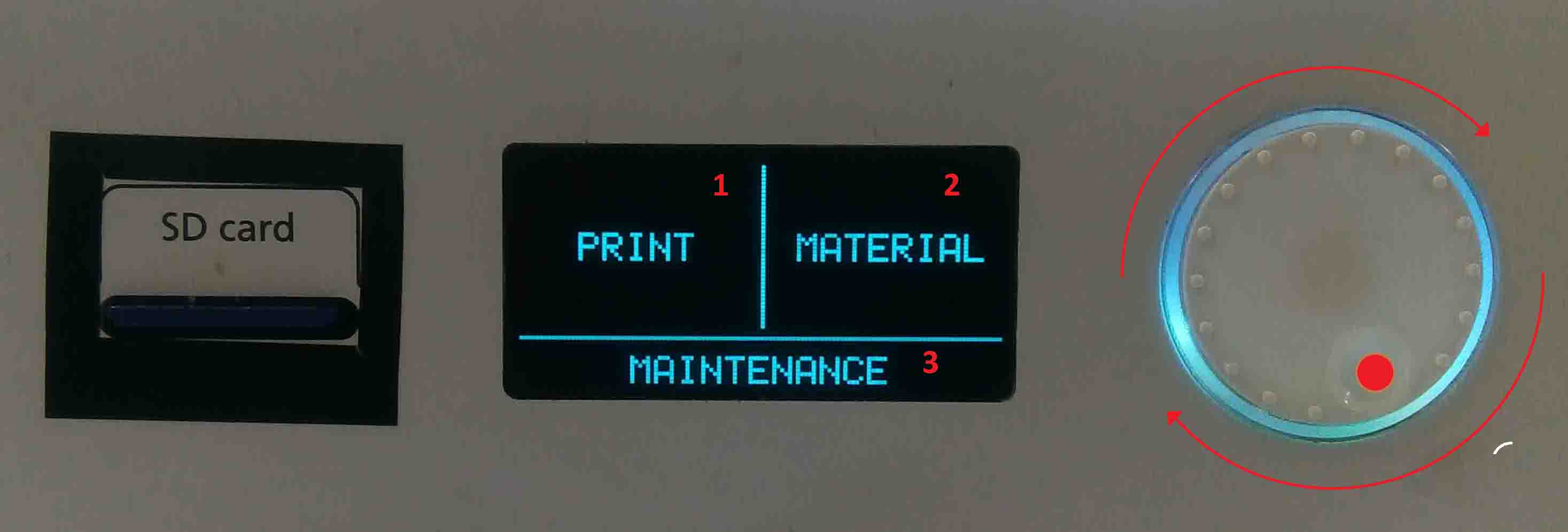
In the display, There are three options:
- Material
- Maintenance
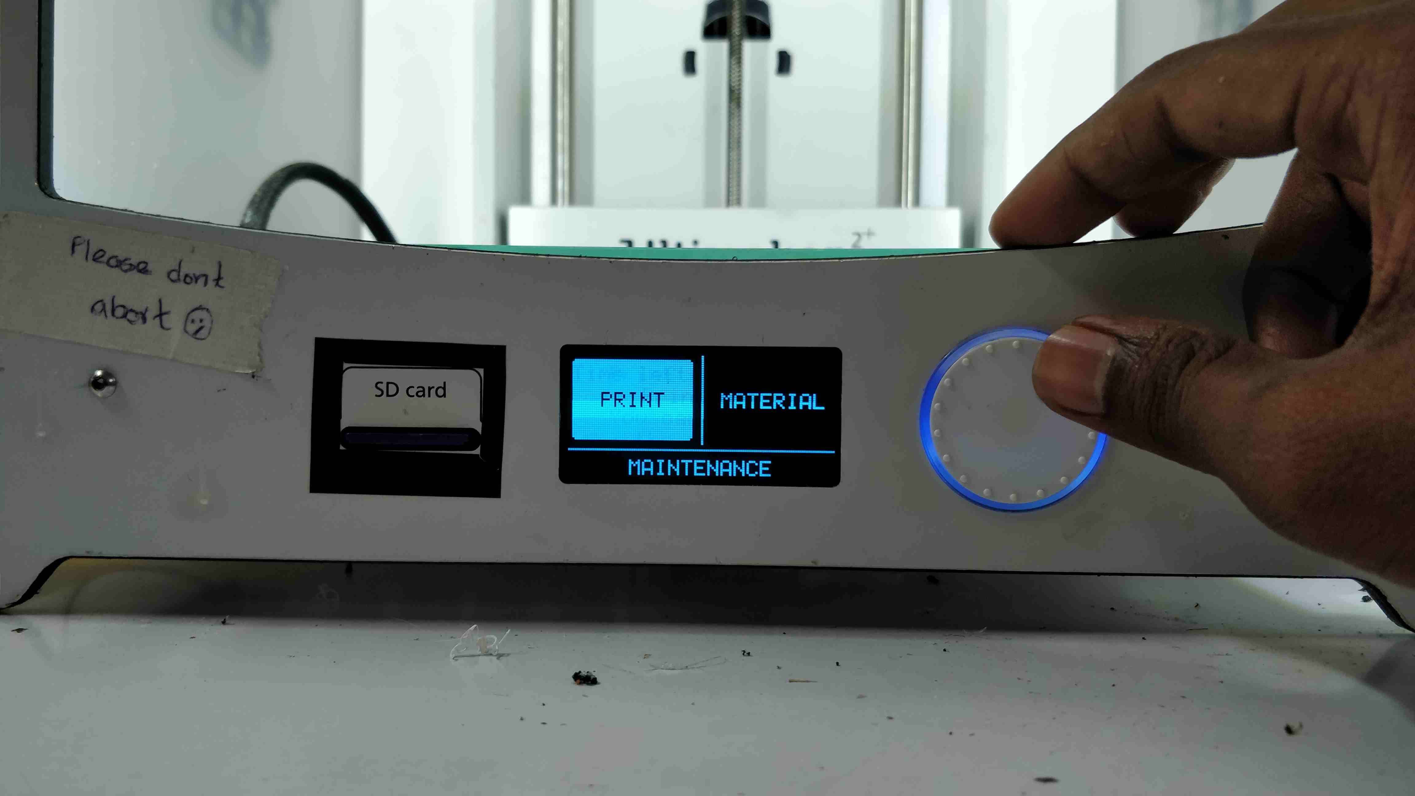
- Select and press "Print"
- Select our File
- Wait for the machine to heat
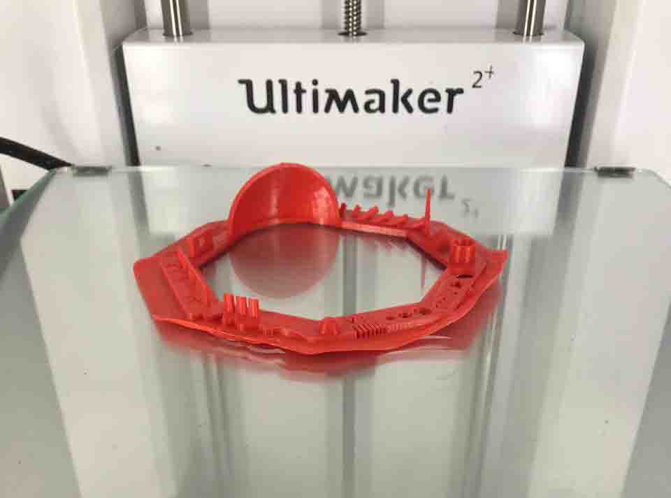
Hero SHOT
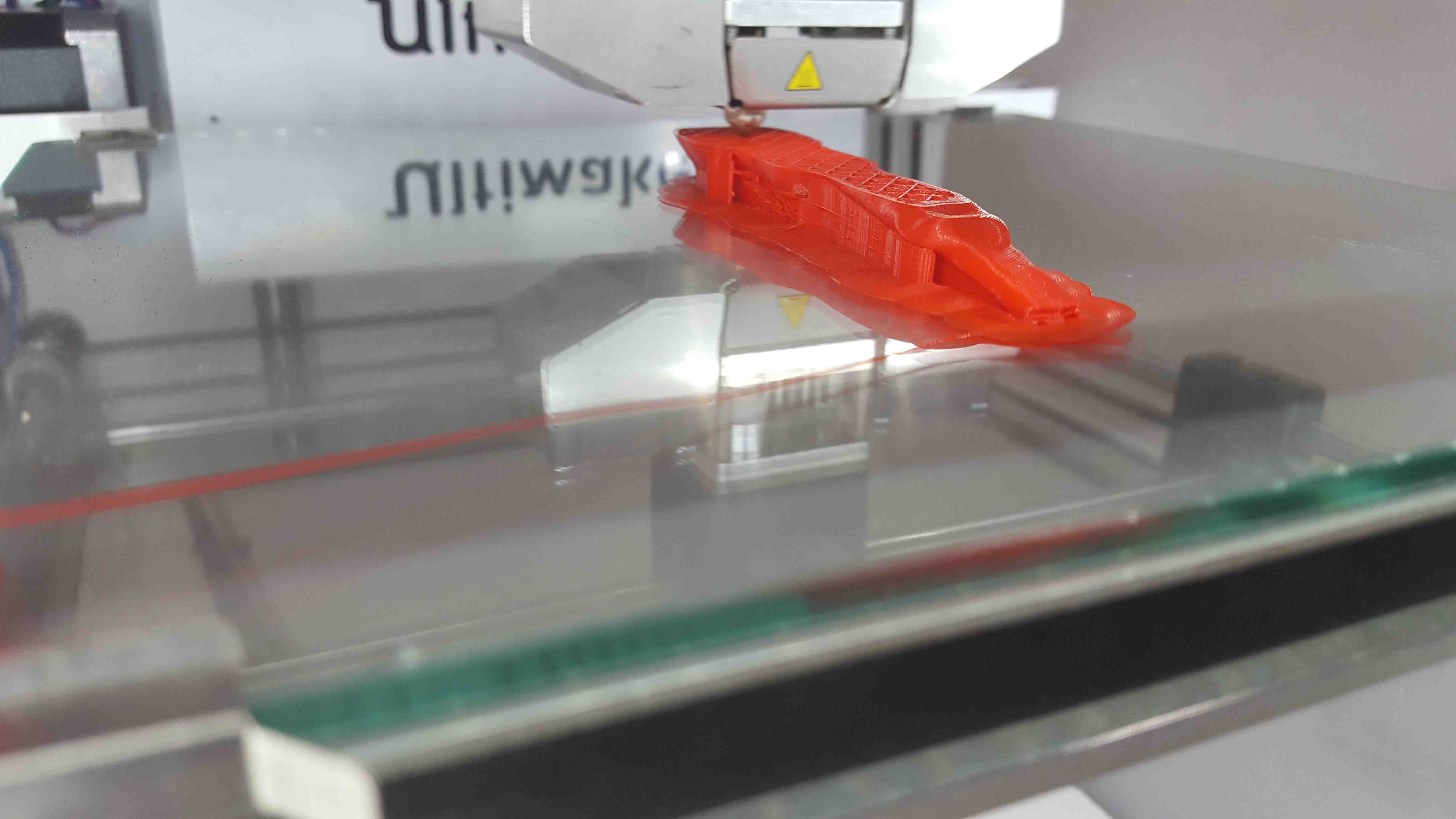
I just try to print this,
After printing i juse breake the bond of ball with wall. and its working fine
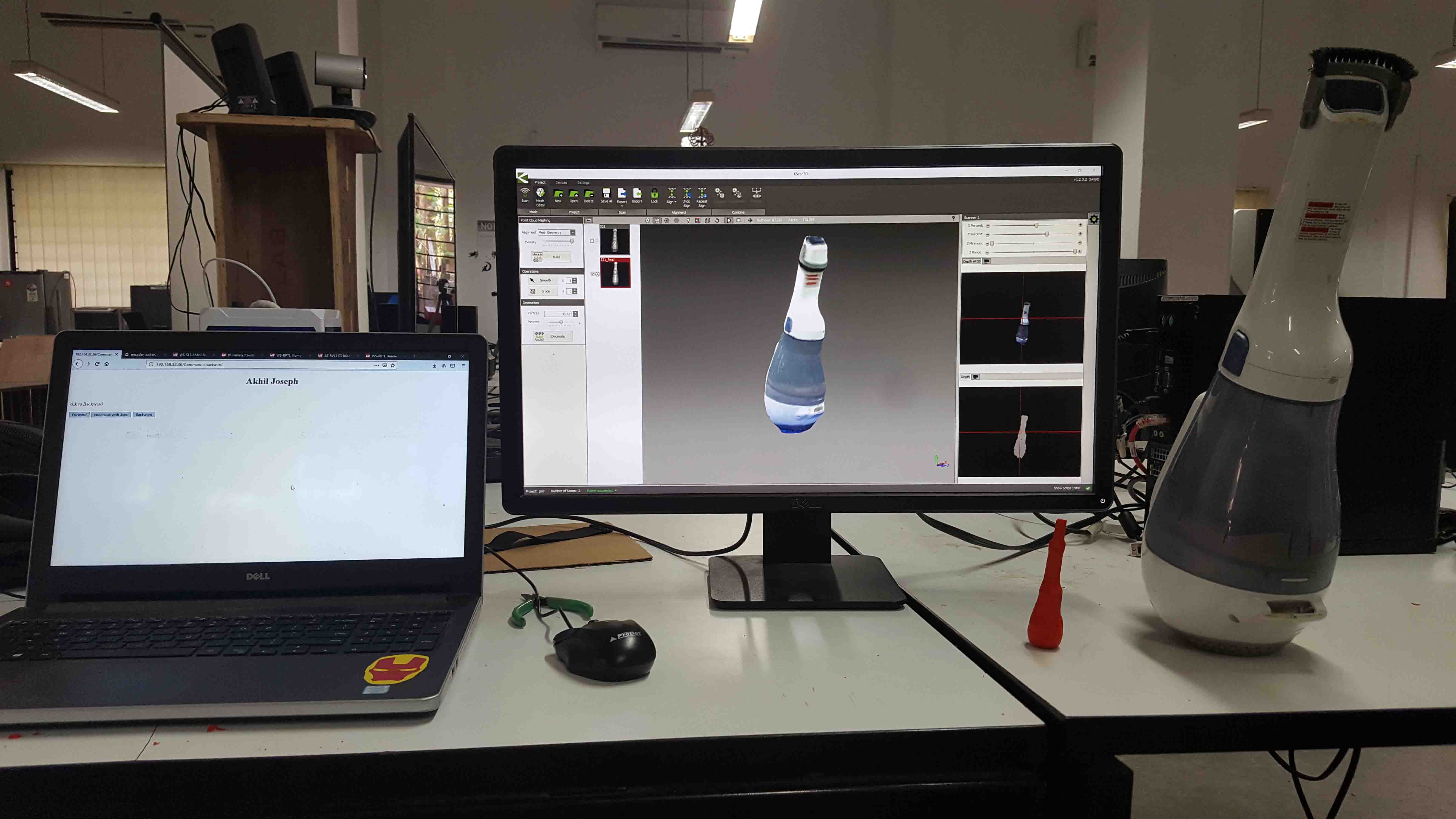
3D Scaning
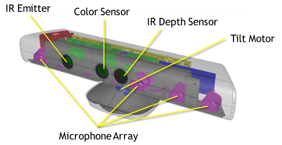
I use Microsoft KINET 3D to scan vaccom cleaner
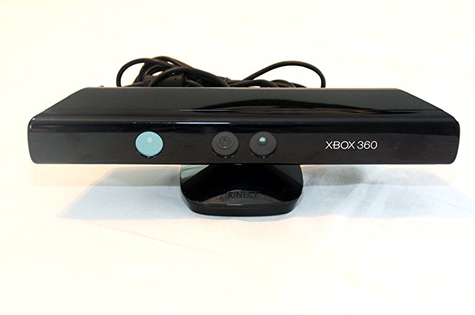
This is a combination of sensors and camera mounted on a rotating platform
I just try to Scan a vaccome cleaner in my LAB.
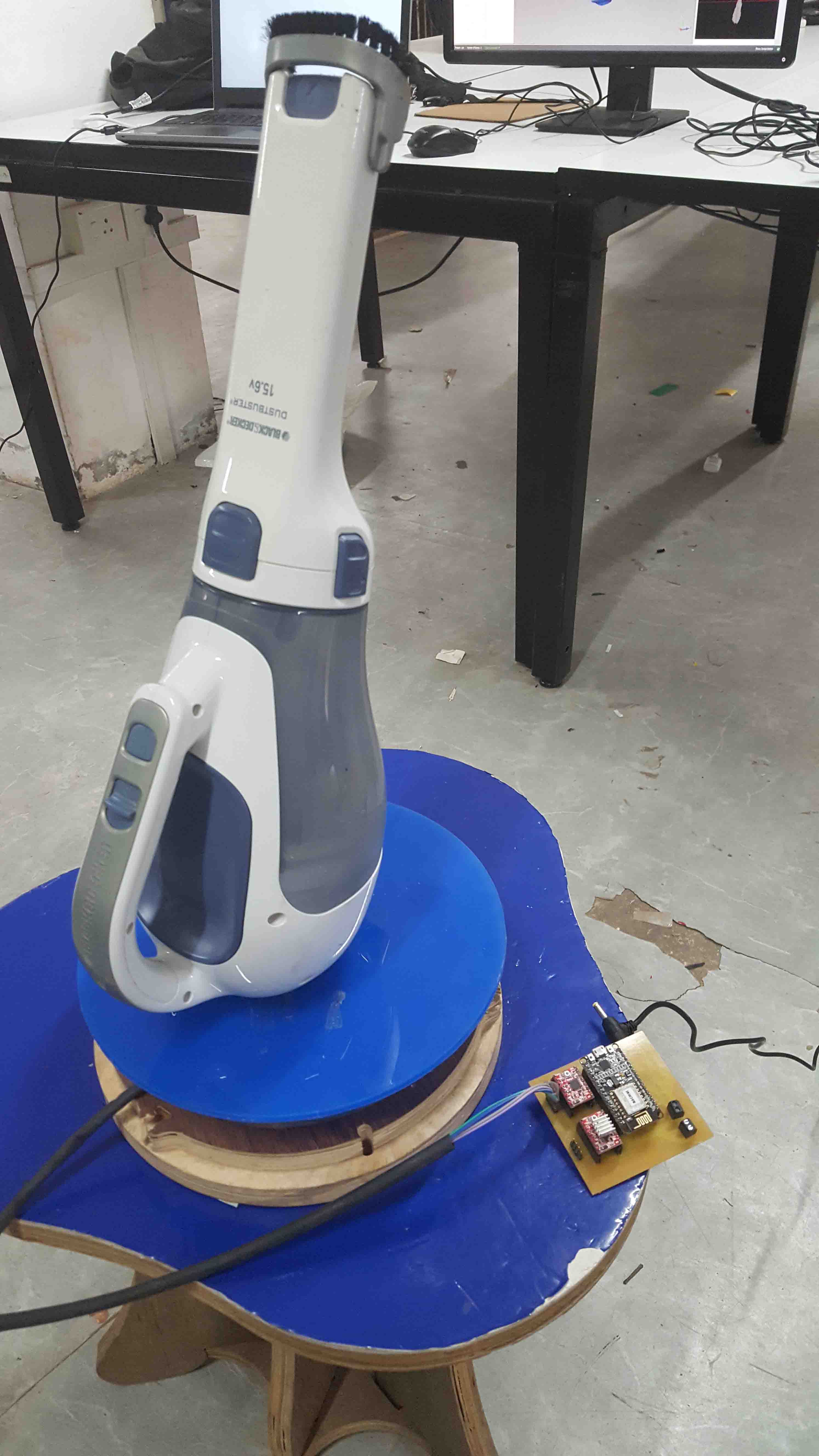
we made a rotating platform using stepper and ESP8266 which can be controled over WEB dashboard

I use Kscan 3D software to scan vaccom cleaner
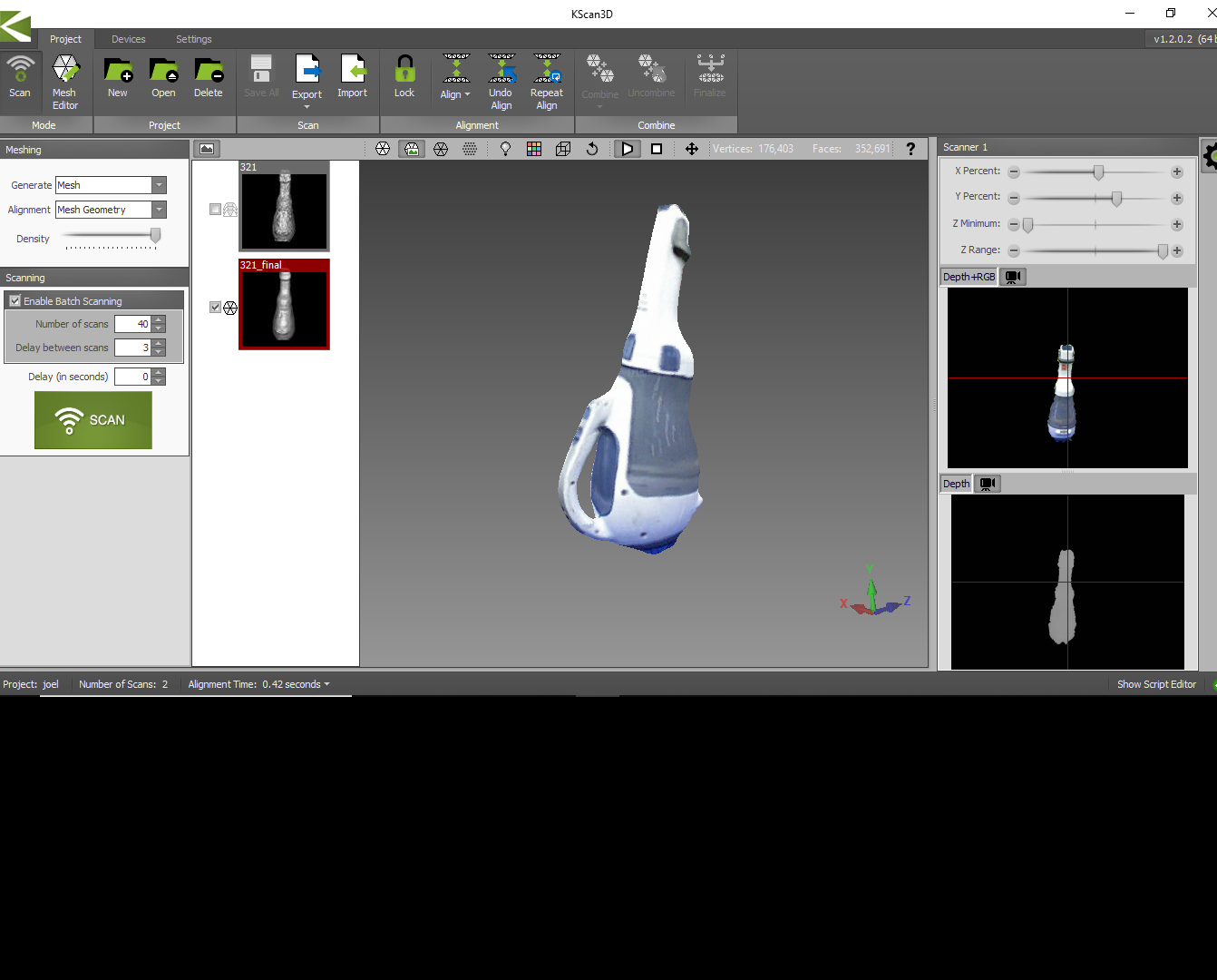
MESH Editing:
The model we obtained during the last process is a 3D mesh geometry . Since we didn't scanned the bottom area there is a hollow section under the model . We need to clear the void and need to convert it in to a solid model.
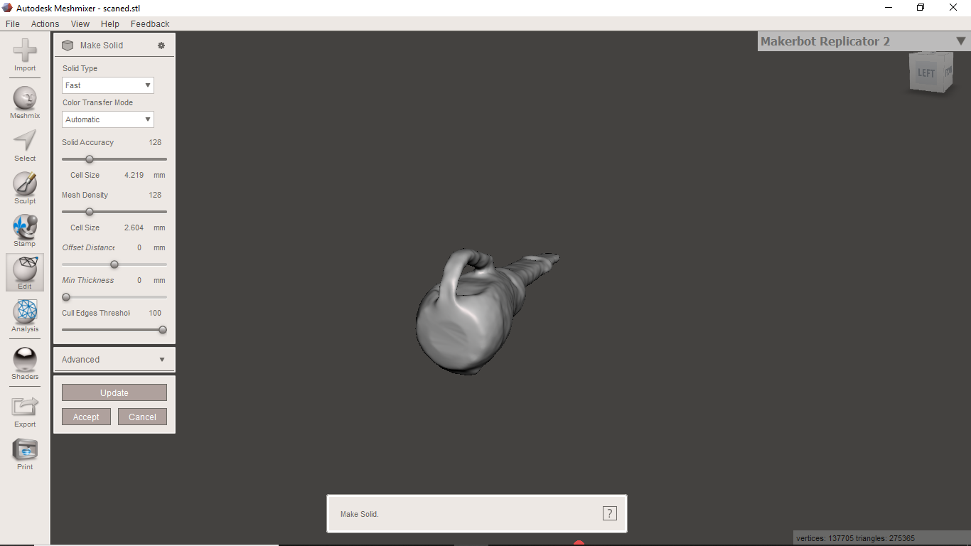
I used an tool called meshmixer to edit the mesh geometry. It is very easy to use.
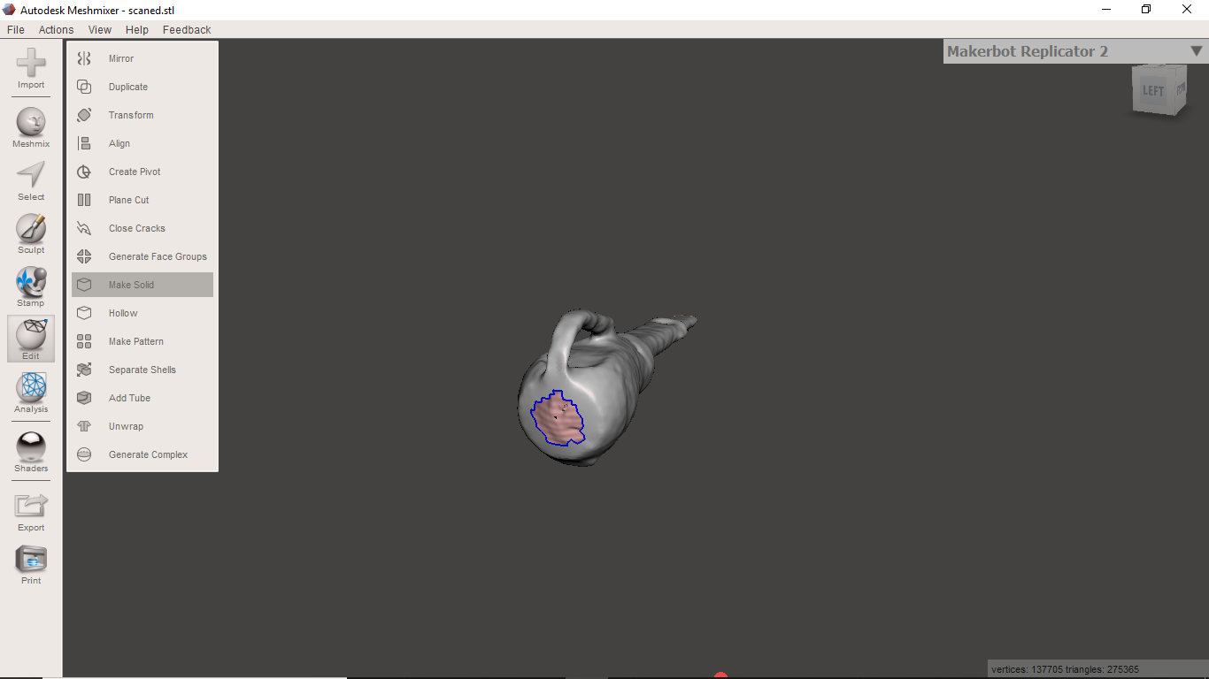
This tool have an option make solid which will make all holes closed
And finaly we got following output
And after i jst try to print it.
i print it in 3D printer in my LAB