Electronics Production
So it's the 4th week since I begin my fab journey. In this week, I got following assignments,
- Make an in-circuit programmer by milling the PCB
- Optionally, trying other processes
So we are going to make an ISP. I have 2yr experience in Embedded System. So i used ISP's before and I am well trained in soldering and electronics field. So this week's assignment was not that complcated to understand. And i also usd a CNC mill to fabricate a PCB.
Modella MDX 20
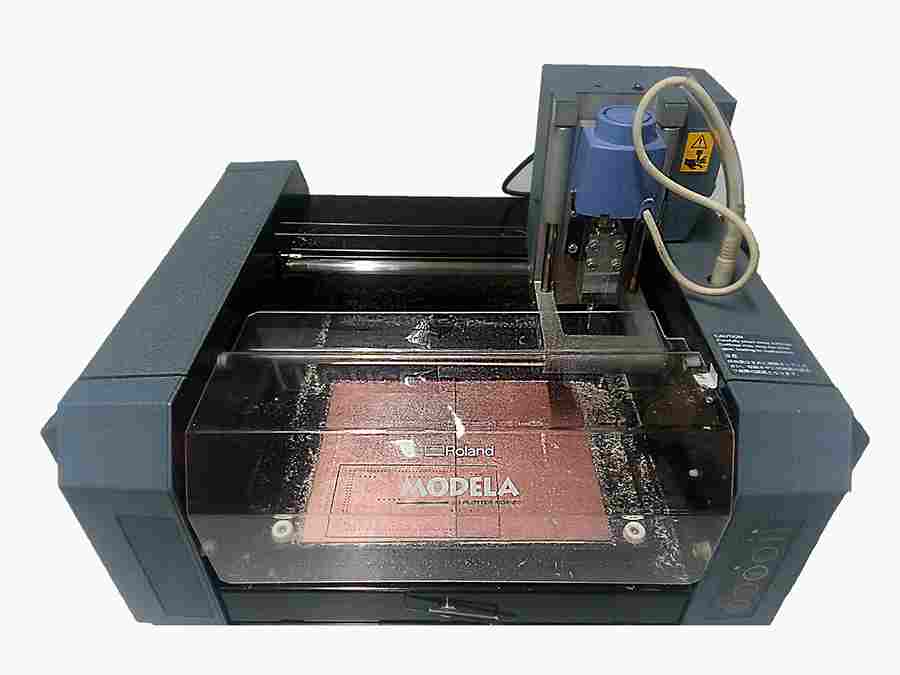
The Roland Modela MDX-20 is a small milling machine and a 2 1/2D precision scanner.This machine is mostly used for milling circuit boards, though it can also mill in other soft materials like machinable wax. For milling circuit boards you should export you design into a black&white monocroome png. For milling out 3 dimensional molds you should export your design as .stl. The second use of this machine is scanning. It uses a thin needle to gently touch the object and calculates from this a 2 and a half dimensional model. Though slow at processing, it can create a high detailed model.
So lets meet it's parts
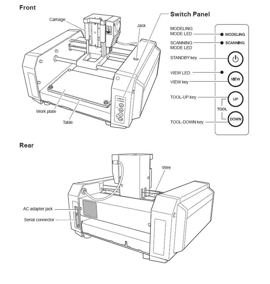
We use CNC mill for making PCB boards. You can download the User's manual here
Preparing CNC
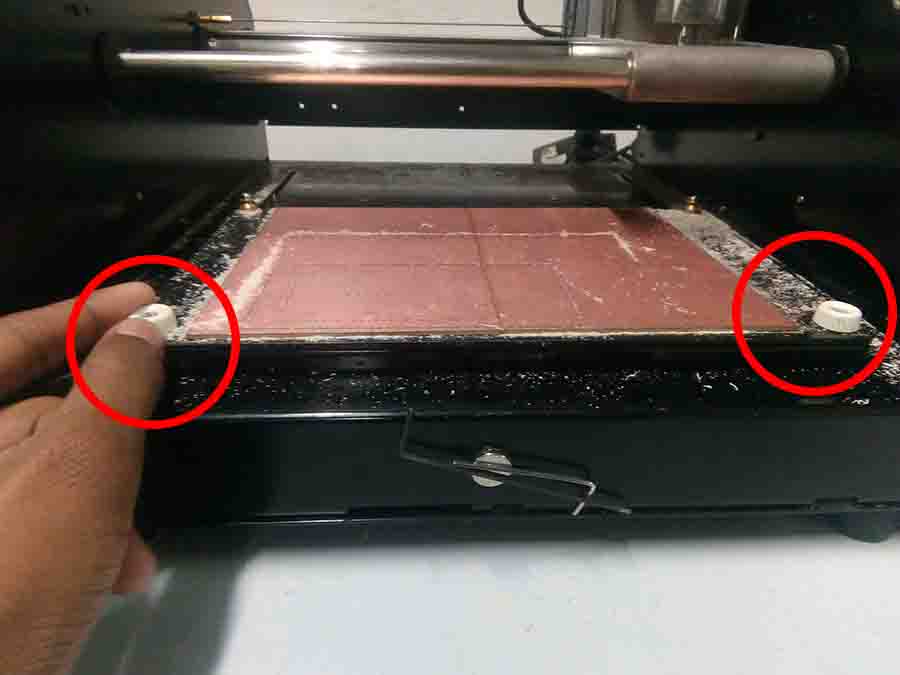
Before we start to mill PCB, we need to check whether the bed and sacrificial layers are up for the job. It might take more damage from previous works.
For fixing it, follow these steps..
- Remove lid from the top
- Seperate the sacrificial layer from the bed
- Remove screws to seperate the bed from the machine
- Now clean the bed and put back into the machine
- Attach a double side tape to the back of the new sacrificial layer and stick it on the bed
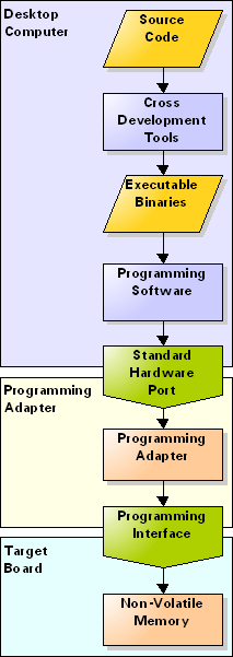
In System Programming
In-system programming (ISP), also called In-Circuit Serial Programming (ICSP), is the ability of some programmable logic devices, microcontrollers, and other embedded devices to be programmed while installed in a complete system, rather than requiring the chip to be programmed prior to installing it into the system.-wiki
FabTinyISp
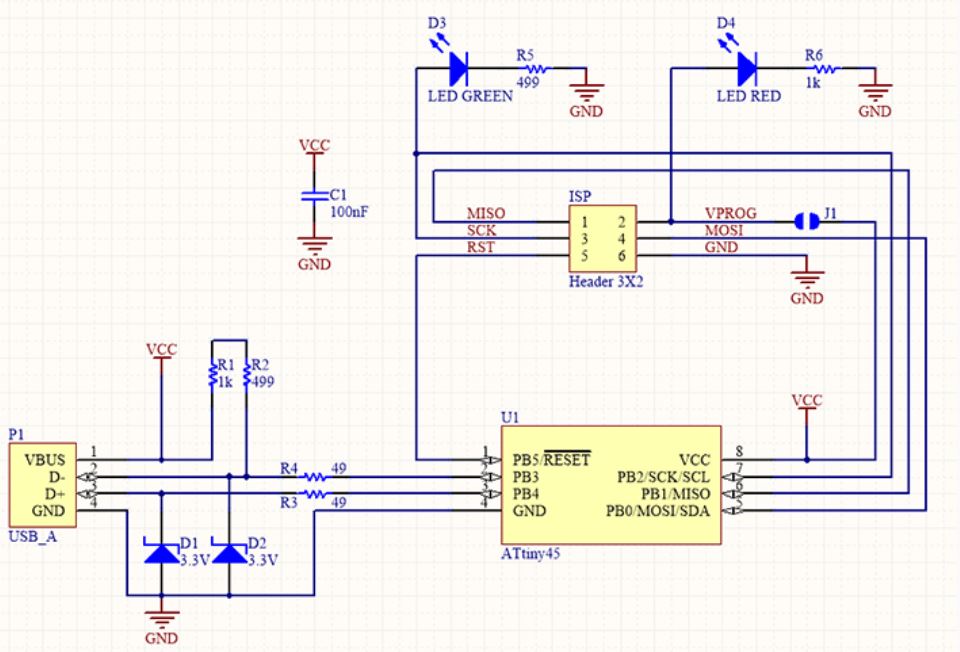
It is a ATtiny45 based board having high-performance, low-power Atmel 8-bit AVR RISC-based microcontroller combines 4KB ISP flash memory, 256-Byte EEPROM, 256B SRAM, 6 general purpose I/O lines, 32 general purpose working registers, one 8-bit timer/counter with compare modes, one 8-bit high speed timer/counter, USI, internal and external Interrupts, 4-channel 10-bit A/D converter, programmable watchdog timer with internal oscillator, three software selectable power saving modes, and debugWIRE for on-chip debugging. The device achieves a throughput of 20 MIPS at 20 MHz and operates between 2.7 - 5.5 volts.I choose Brian's verson because this design doesn't have any clock circuits and additional LED's are there to indicating the status of the board while programming.
Schematic
Position Diagram
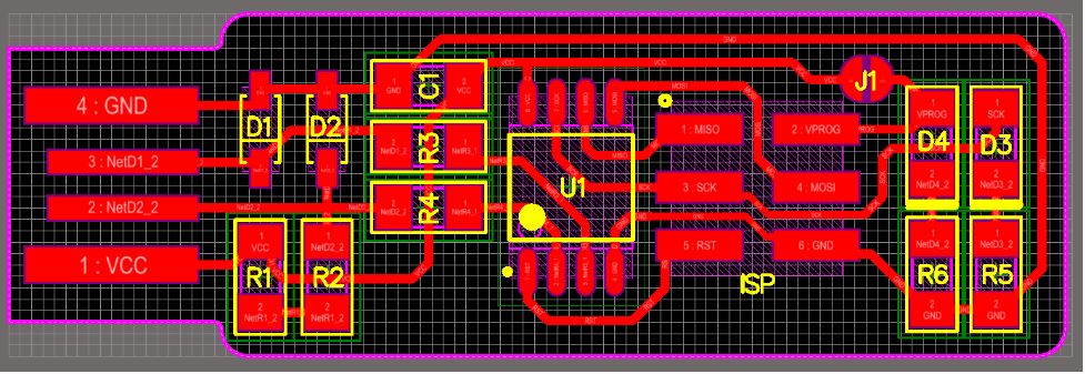
Layout

Setting up the fab modules
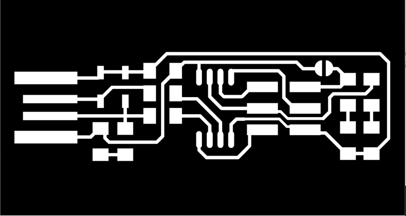
To make the PCB, first we have to setup the fab modules. For that we have to open fab modules in the computer in order to convert the png image into G-code. For that go to the terminal and run fab Now the fab module will open and the select the input format to .png and select the output you want depending on your machine (modlella MDX 20).
- press ctrl+alt+t to open terminal
- enter cammand
fabthen press enter - select
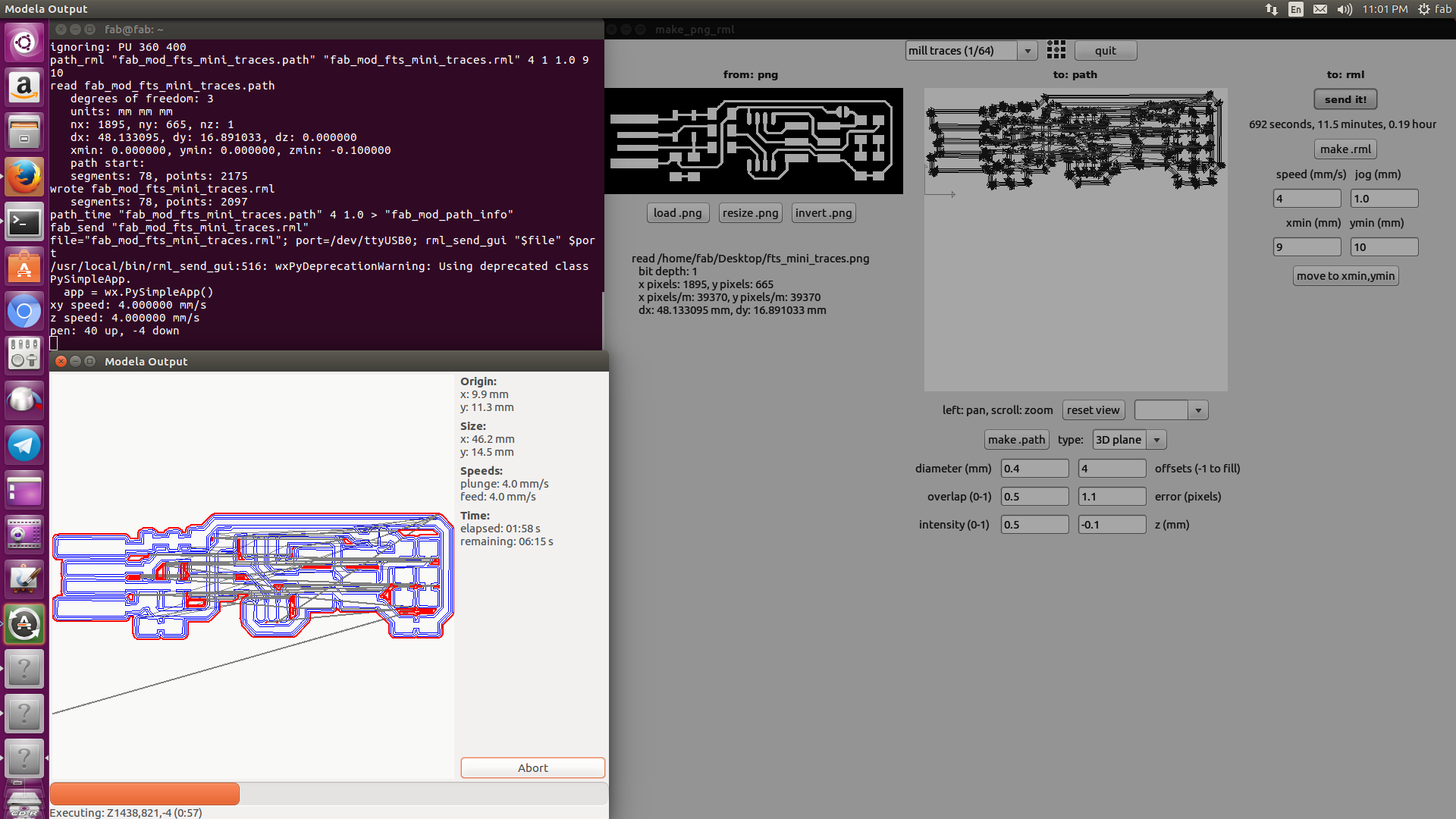
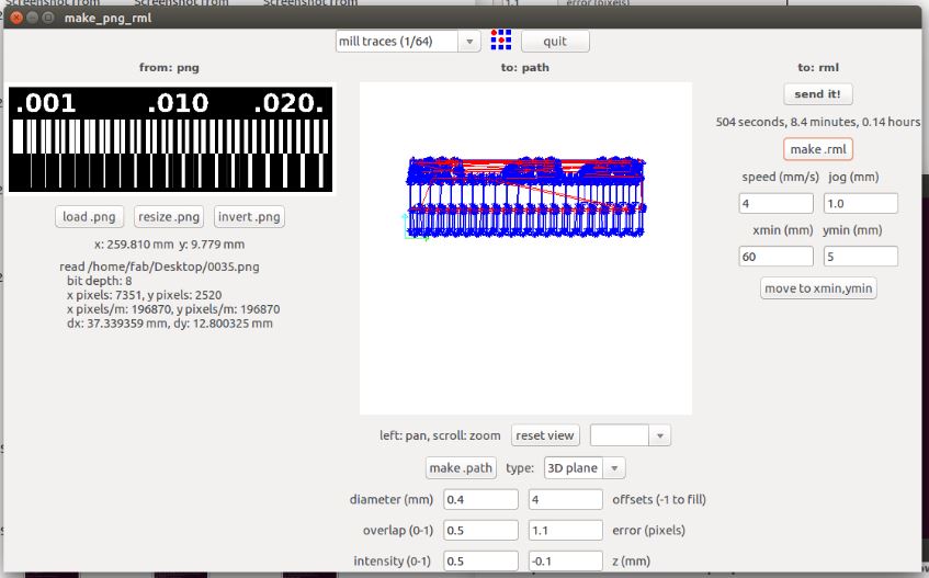
Image.png, set machine asRoland MDX-20 mill(.rml)and entermake_png_rml - Now press
load pngand select the image that you wanna mill. Then selectmill traces(1/64)and pressmake.path. After processing pressmake.rmland prepare the PCB for milling.
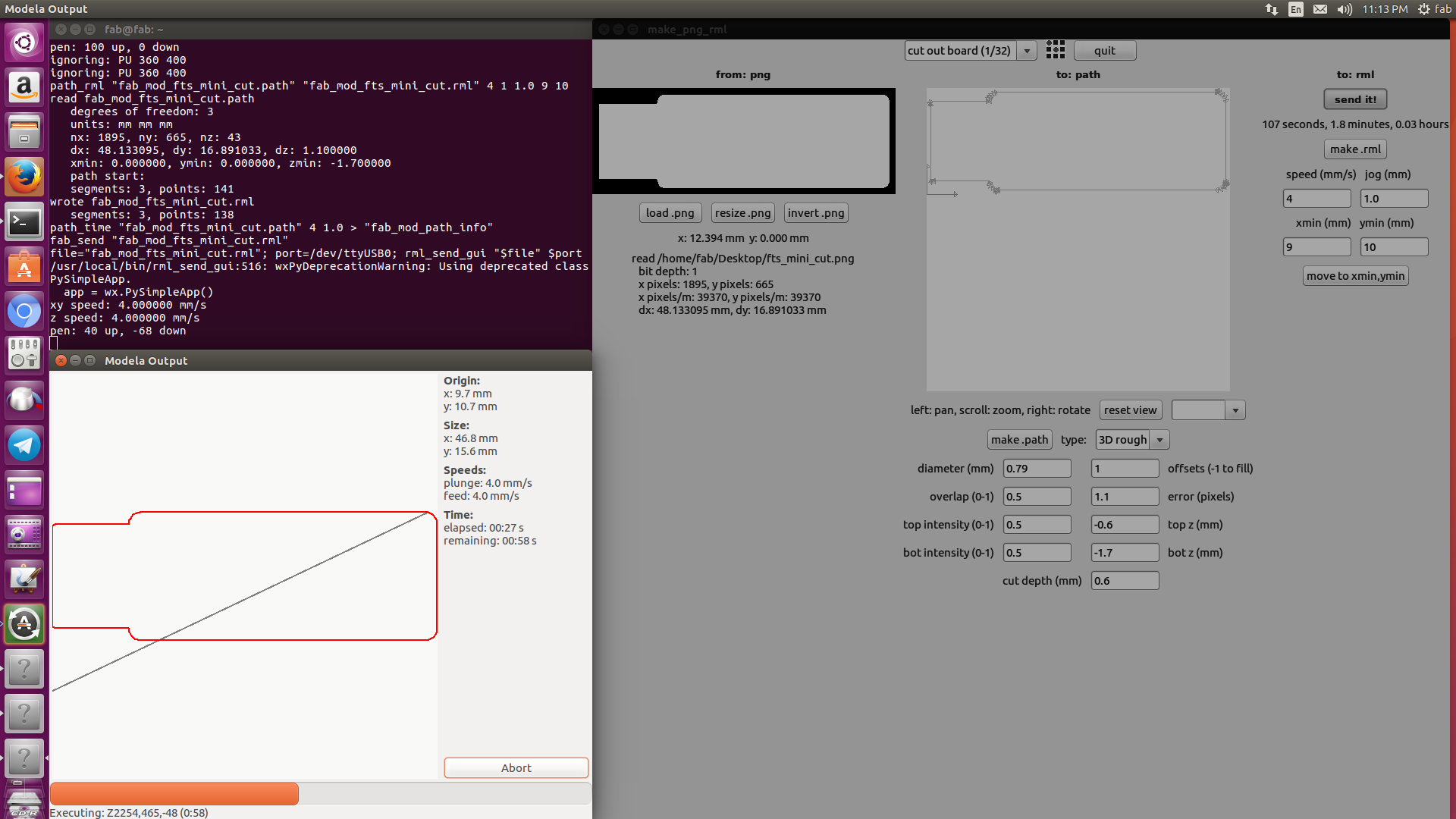
To do cutting, change the milling bit with cutting bit and repet the above steps with cuting trace png image.
Now we got a finished board. Let move to soldering
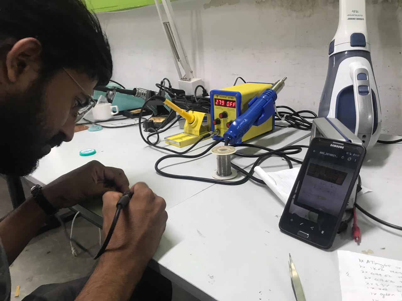
soldering
Soldering was a fun job. I am very good at soldering. so this task was very easy for me. I begin with making a list of the components that I am going to use.
Parts
- 1x ATtiny45 or ATtiny85
- 2x 1kΩ resistors
- 2x 499Ω resistors
- 2x 49Ω resistors
- 2x 3.3v zener diodes
- 1x red LED
- 1x green LED
- 1x 100nF capacitor
- 1x 2x3 pin header
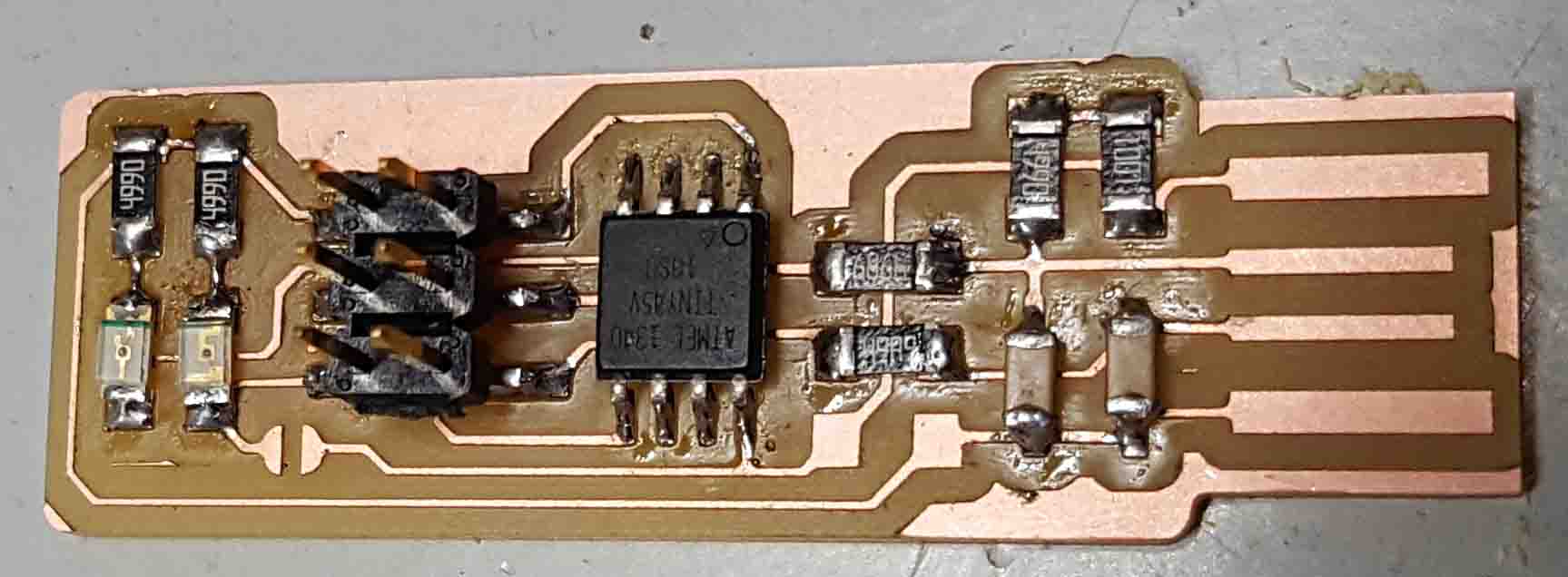
I have some experience in SMD soldering, and i also have experience in assembly line pik&place machine. so this is not a difficult task for me
After that I solder every components one after an other. I got a good board after that.
Programming ISP
What we make is just a hardware. It is useless without it's software part. So we need to upload the program code for the fabISP.I using Linux , so first we need to install avr-gcc tool-chain, type this on terminal to install tool-chian
sudo apt-get install avrdude gcc-avr avr-libc make
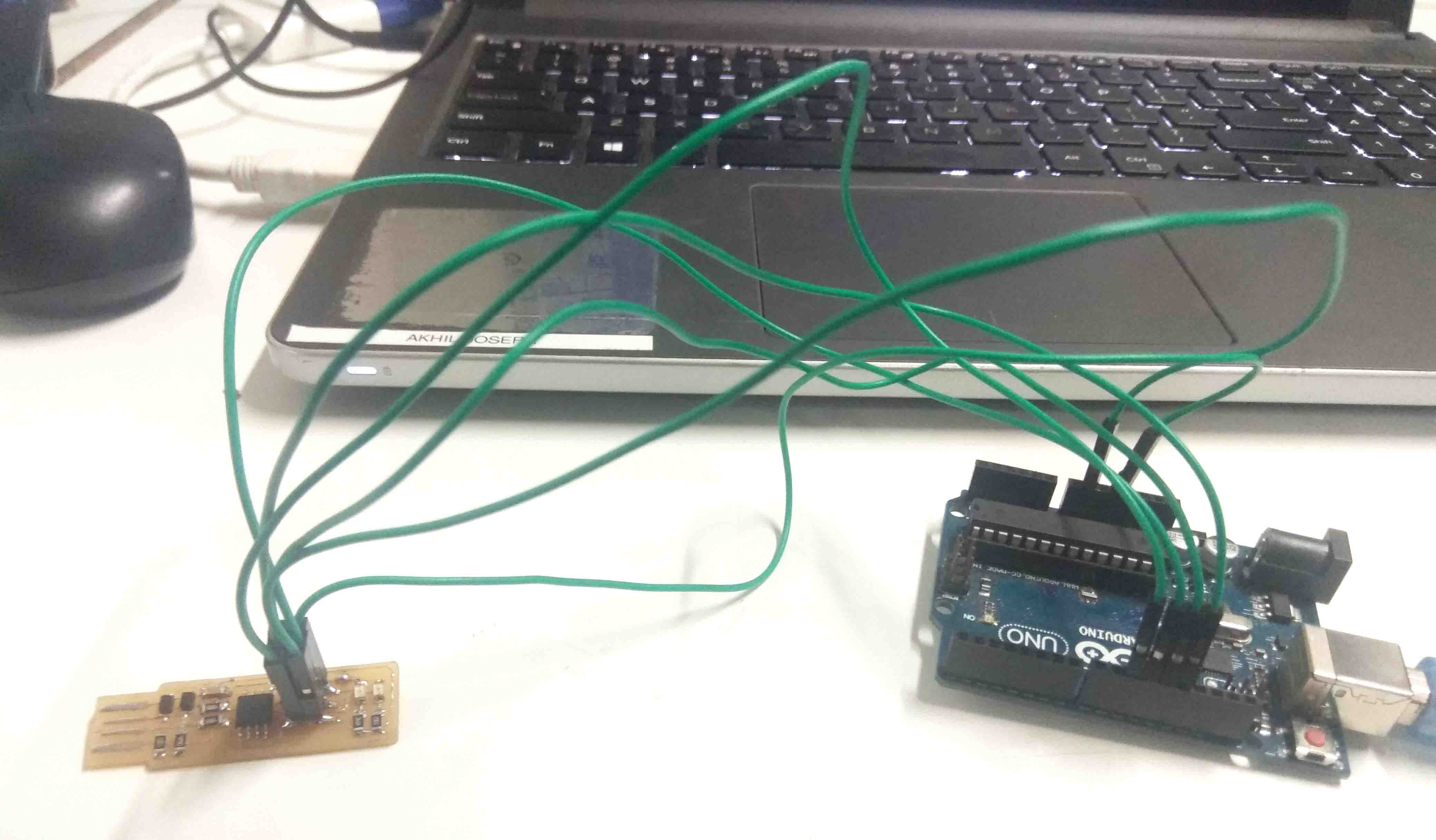
We can programm a chip using different tools. The ATtiny45 chip need to be flashed inorder to work as ISP. In my LAB There is one AVR programer but its is not working, So i take an arduino UNO Board to program FAB isp whichi made. I have used Atmega328 chip.The FabISP can be connected to arduino uno board using male to female cables.
Turn arduino into an ISP
Arduino Uno board contain an ISP and ATMEGA chip.AtMEGA chip offers input output terminals. Some male to female jumper cable is connected between ATtiny45 and arduino pins.Arduino Uno board is connected to computer and run the Arduino IDE program.
- Select TOOLS>BOARD>ARDUINO UNO.
- Select TOOLS>PORT>/dev/ttyACM0
- Select FILES>EXAMPLES>ARDUINO ISP>ARDUINO ISP.
- Click UPLOAD.
Now the program is uploaded to ATMEGA chip in arduino uno board. The blinking LED's indicate the program is being flashed. If the program return an error "permission denied", follow the steps mentiones below
- Open terminal window by ctrl+alt+t
- Go to arduino directory by
cdcammand - then enter cammand
sudo ./arduinothen press enter. - This will ask your password, enter it and press enter
- after that go to previous steps to uplode the icsp program to arduino.
Then Downlod Fimwere to flash new ICSP. then Unzip it to a folder
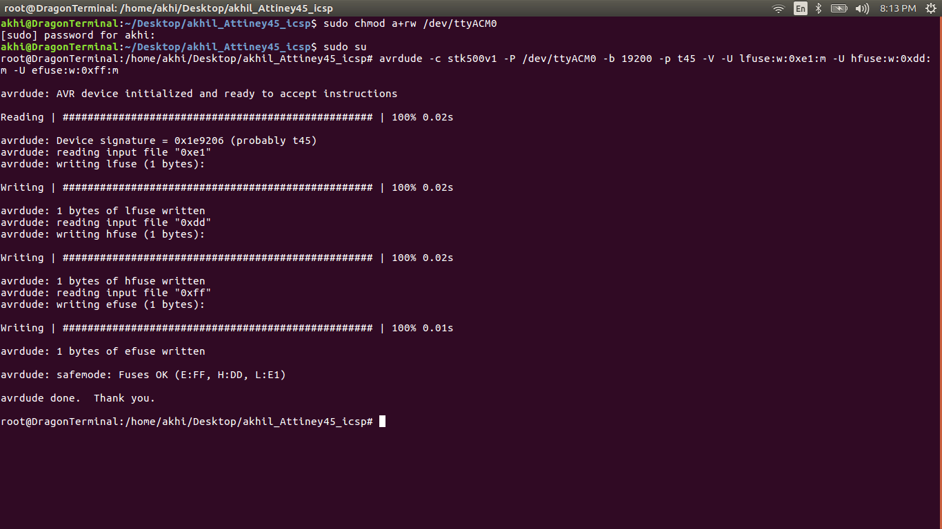
Download filesThe next task is burning fuses in ATtiny45 chip. The fuses determine how the chip will act, whether it has a bootloader, what speed and voltage it likes to run at, etc. The fuses given in the below comand is hexadecimal representation. (lfuse:w:0xe1:m hfuse:w:0xdd:m efuse:w:0xff:m). This hexadecimal representation is elobrated in the left picture below and the command for burning fuses is shown below.
avrdude -c stk500v1 -P /dev/ttyACM0 -b 19200 -p t45 -V -U lfuse:w:0xe1:m -U hfuse:w:0xdd:m -U efuse:w:0xff:m
If the program return an error "permission denied", then open a terminal window and enter the command as follows. This command will give permission for the same device. This command should be executed each time the device is plugged in or else you should add udev rules in linux which will get executed automatically each time when the system boots. You can close arduino IDE program if required. If you disconnect your board accidently, make sure its the same device (ttyACM0) when you reconnect or else give the command according to the device name.
sudo chmod a+rw /dev/ttyACM0
I jst irittated to enter sudo password all time, so i activate superuser by enter the cammand sudo su
And go to the task to burning fuses again. By the command again
avrdude -c stk500v1 -P /dev/ttyACM0 -b 19200 -p t45 -V -U lfuse:w:0xe1:m -U hfuse:w:0xdd:m -U efuse:w:0xff:m
The program for ISP needed to be compiled and installed.make hex and make installcommands are used for this purpose. A makefile is a file containing a set of directives used with the make build automation tool. Each compilation produces an object file corresponding to the source file, this source file is installed using make install command. The commands make hexand make install is shown below. This command to be run from the same folder where files are copied. The files for compiling can be downloaded here.
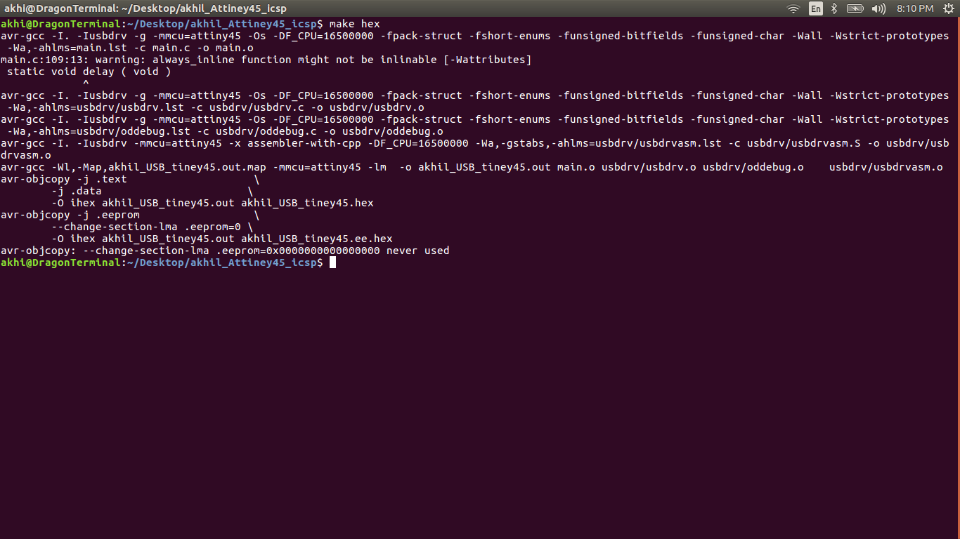
If you made any mistake while compiling, you can undo the operation using the below commands.
make cleanmake distclean
then corrct mistake then run make hex cammand again
After successfully build HEX file enter make install cammand to flash program to FAB isp
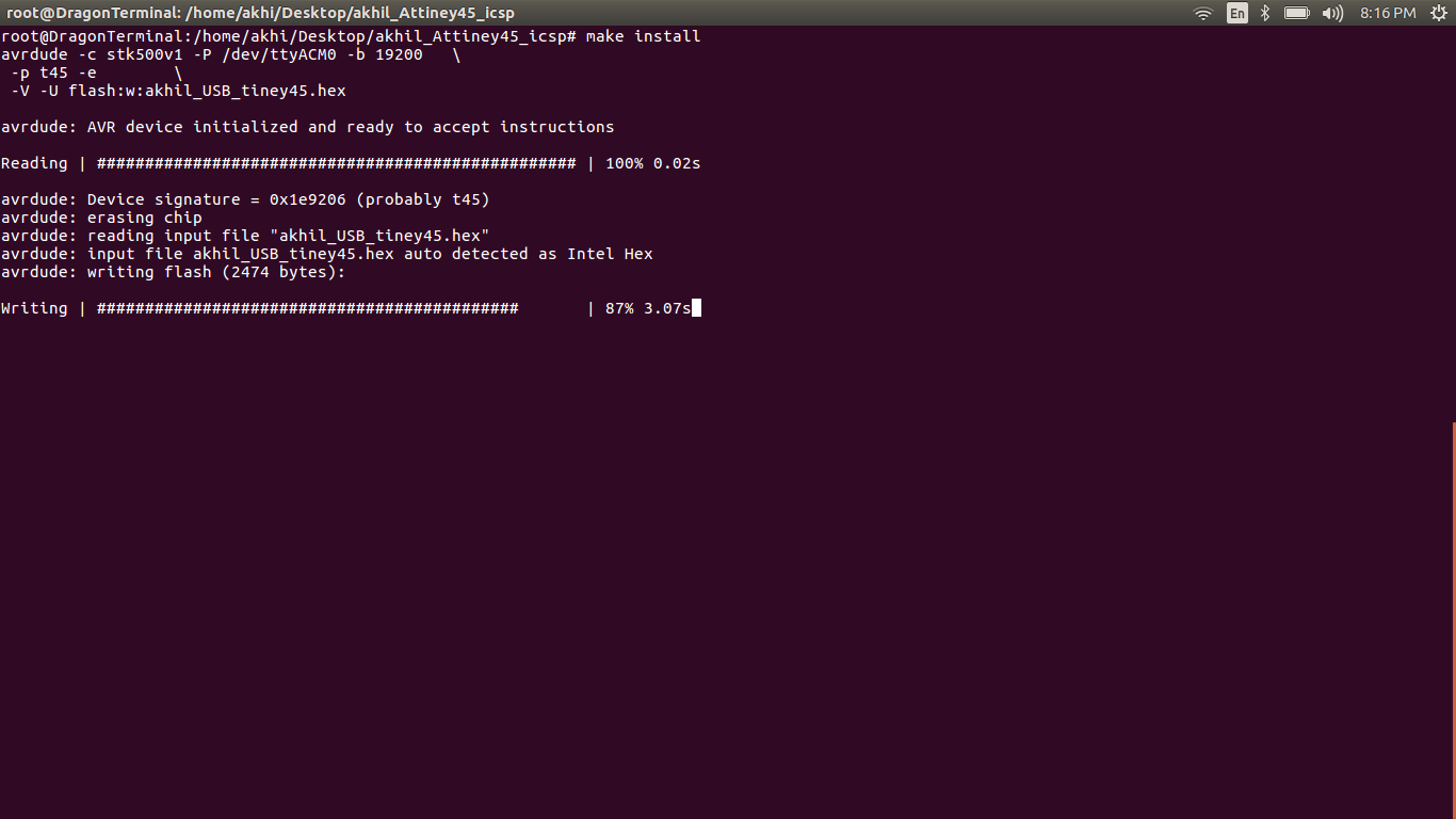
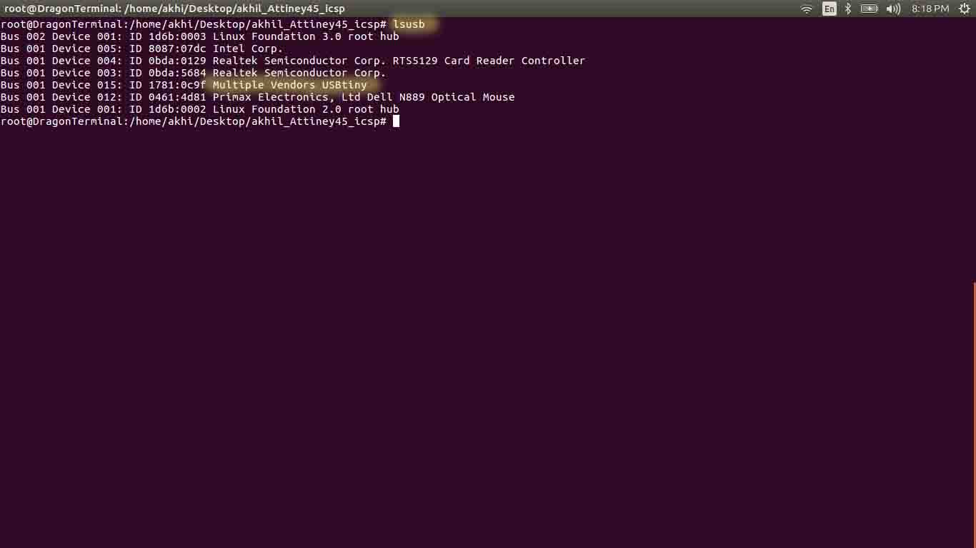
Once after loading, the ATiny45can be disconnected from arduino uno. Now plug it on USB. Open terminal window and enter lsusb and look for the device ID 1781:0c9f - multiple vendors USBtiny. If USBtiny is detected, then ATtiny45 is working as ISP
The next step is Blowing the reset-disable fuse. Make sure everything is working properly before taking this final step. Enter the below command on a terminal window.
avrdude -c tk500v1 -P /dev/ttyACM0 -b 19200 -p t45 -V -U lfuse:w:0xe1:m -U hfuse:w:0x5d:m -U efuse:w:0xff:m
Now we got a working FabISP.The PCB for this project and its compiling files are available for download in this same page.
But i m not much satisfied on it. Because My laptop USb port is littile bit loose for this on board USB. So i deside to build a new one from the scratch. I have some experence in PCB designing, and i use proteus for design PCB. So i start working on it.
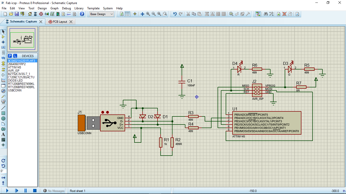
This is the schematics which i make in proteusi also add it to my GIT repo.Anyone can downlod it from heare
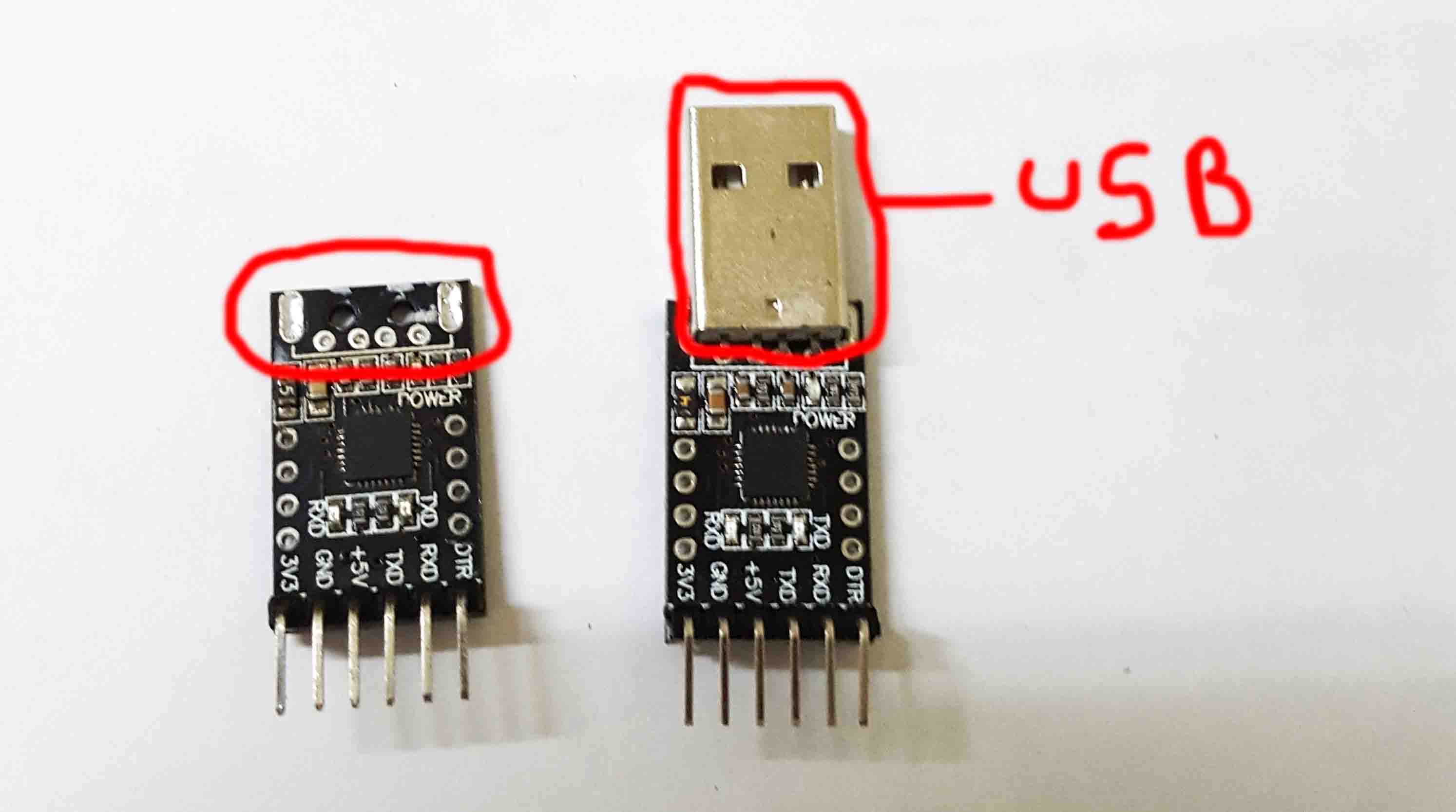
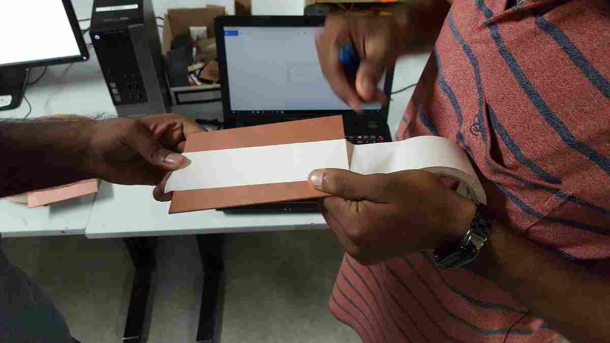
I have a damaged USB to ttl converter, i take it's USB port and i measure it with a Vernier calipper, and with this measurment i make a new footprint in proteus.I have a littile bit dought wether it can be deilled in milling machine because it is a Through hole component.
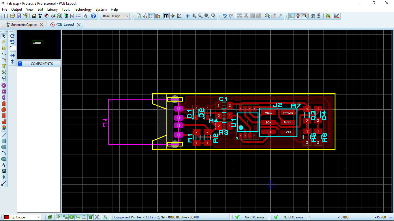
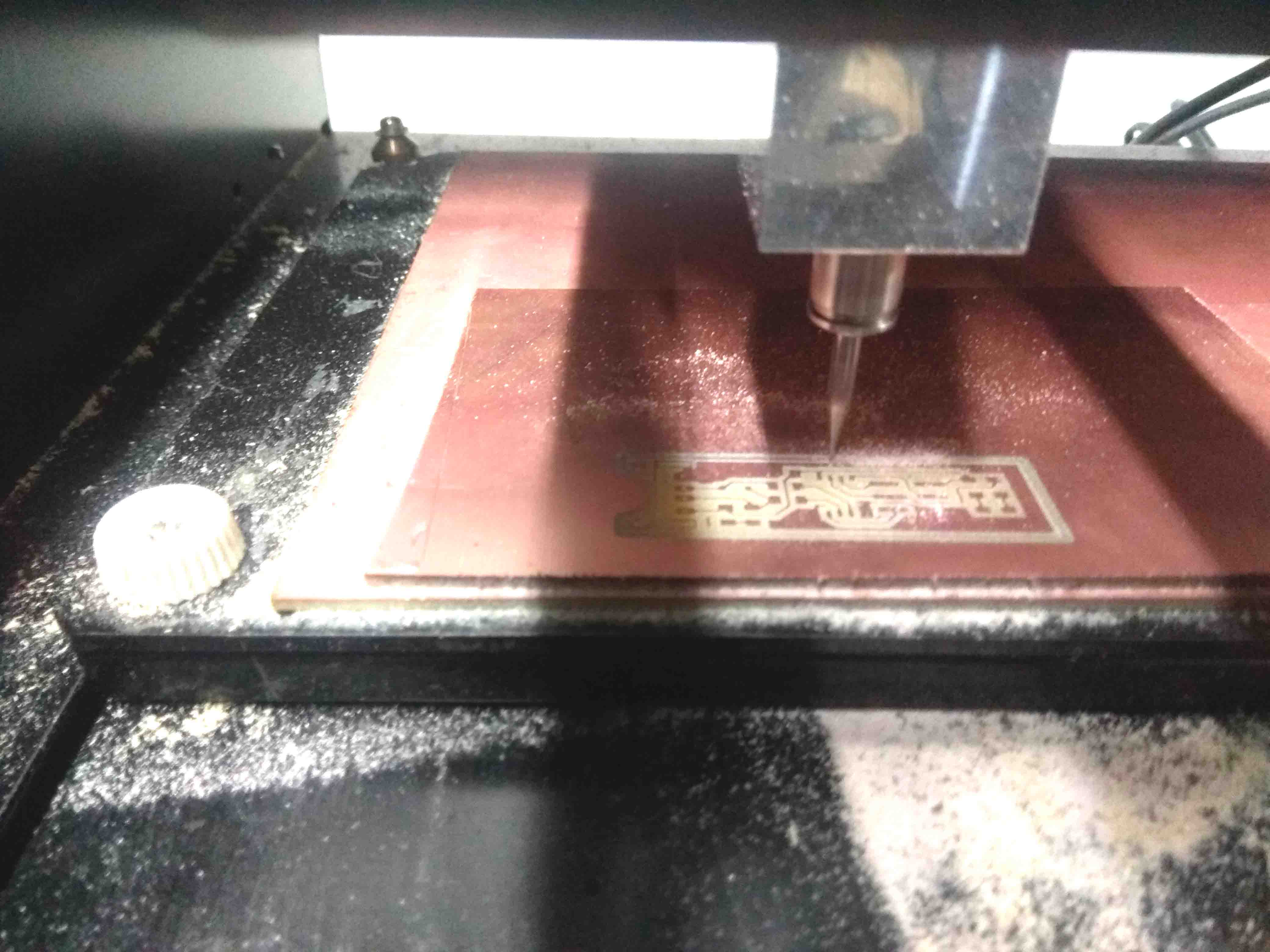
Then i repet the milling procedure which i explaind abue to mill this PCB. the png files can be downloded frome heare


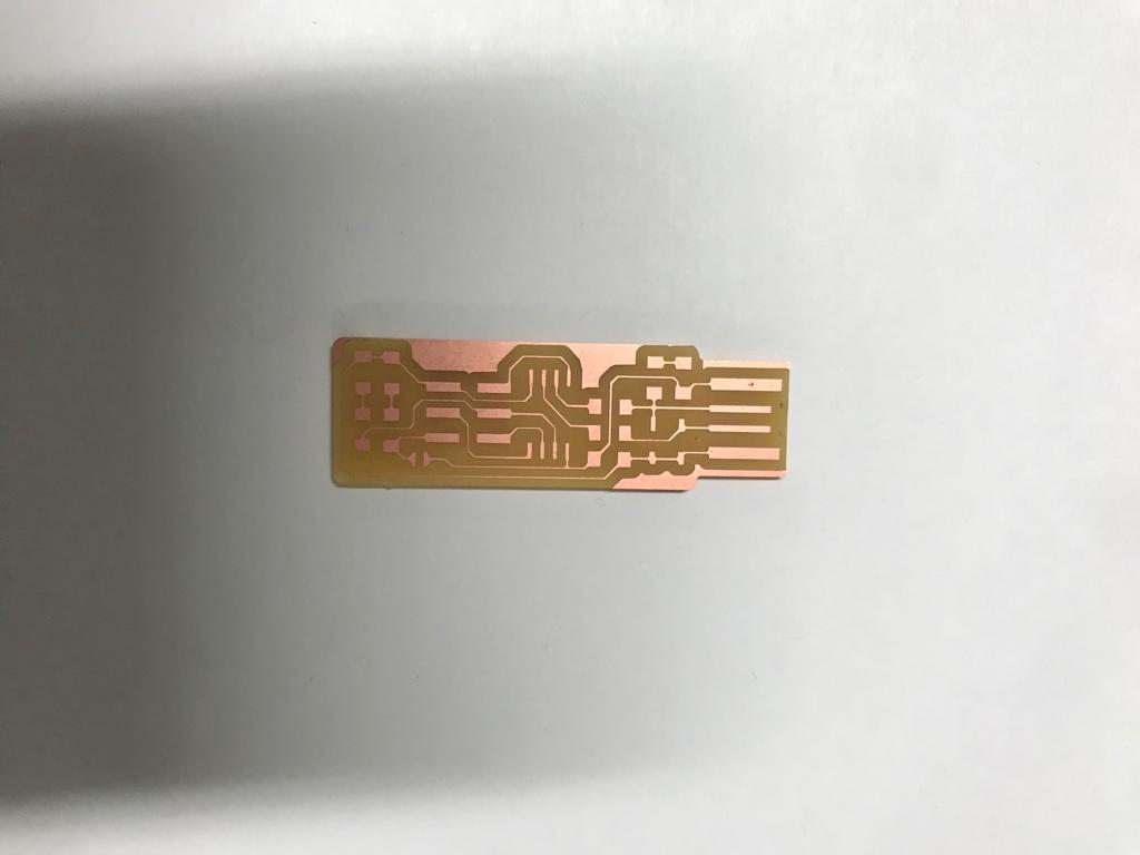
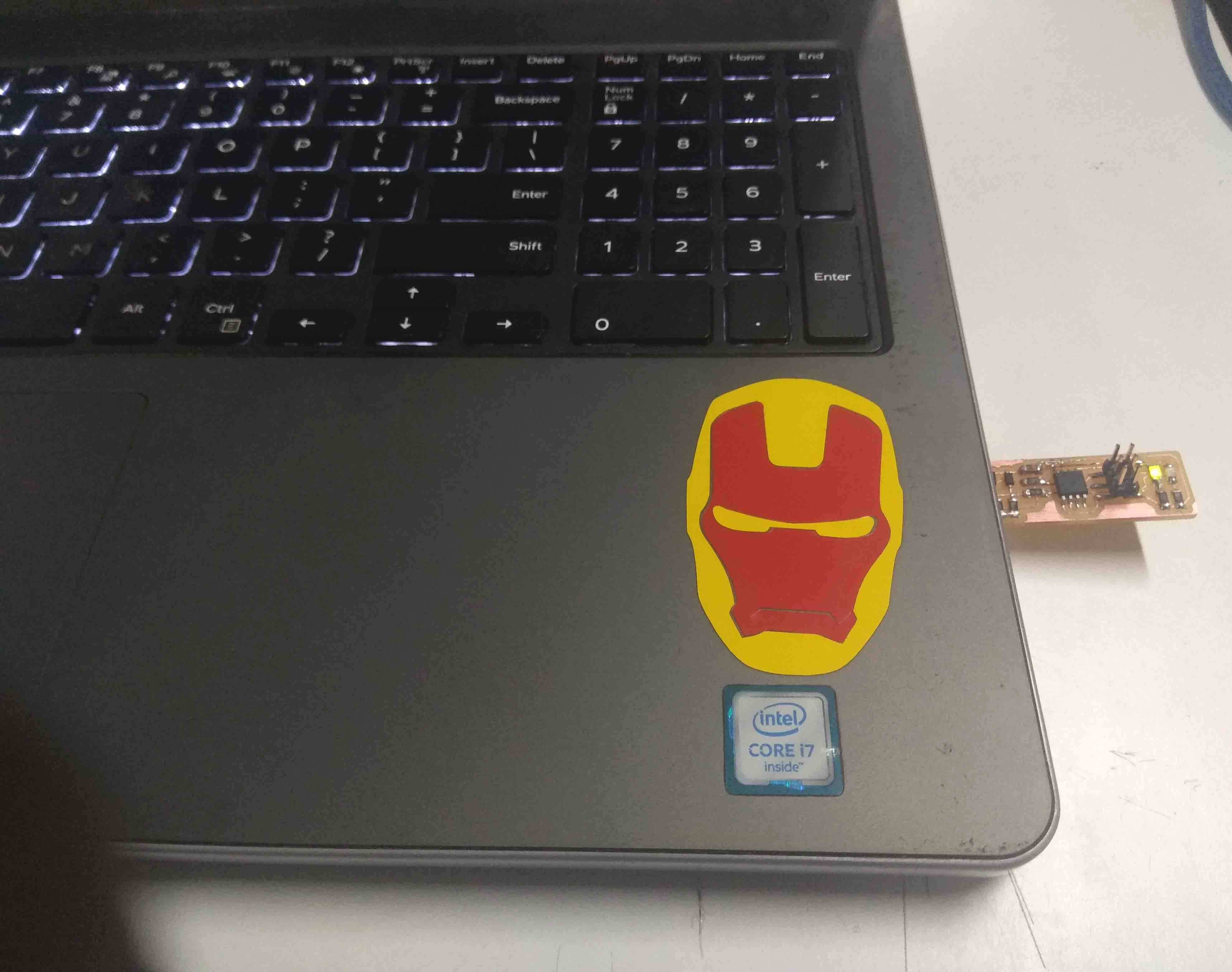
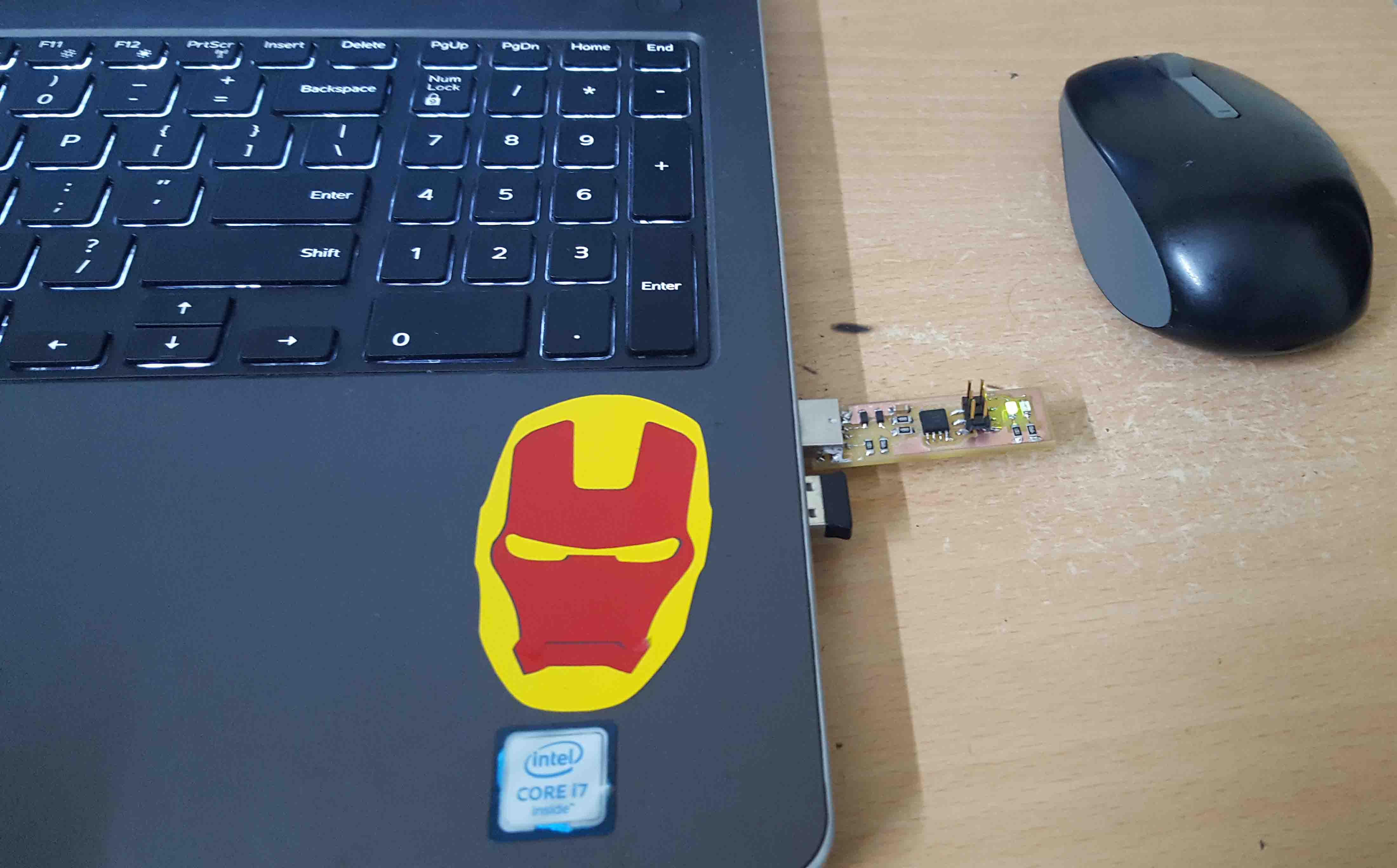
After milling i got the PCB which have a USB socket
Then i solder all the things which i previously used
- 1x ATtiny45 or ATtiny85
- 2x 1kΩ resistors
- 2x 499Ω resistors
- 2x 49Ω resistors
- 2x 3.3v zener diodes
- 1x red LED
- 1x green LED
- 1x 100nF capacitor
- 1x 2x3 pin header
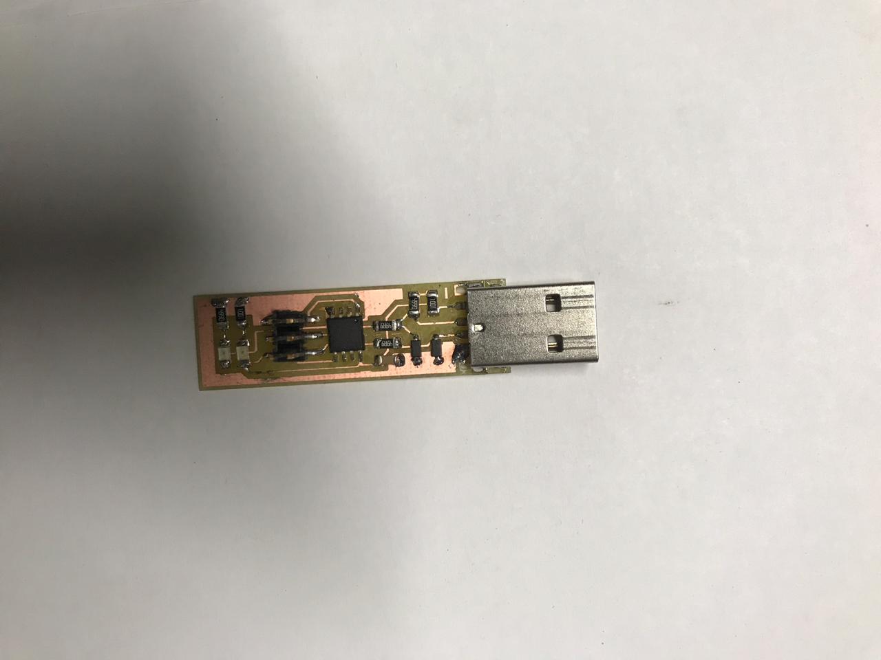
Hero Shot
Programming New Isp
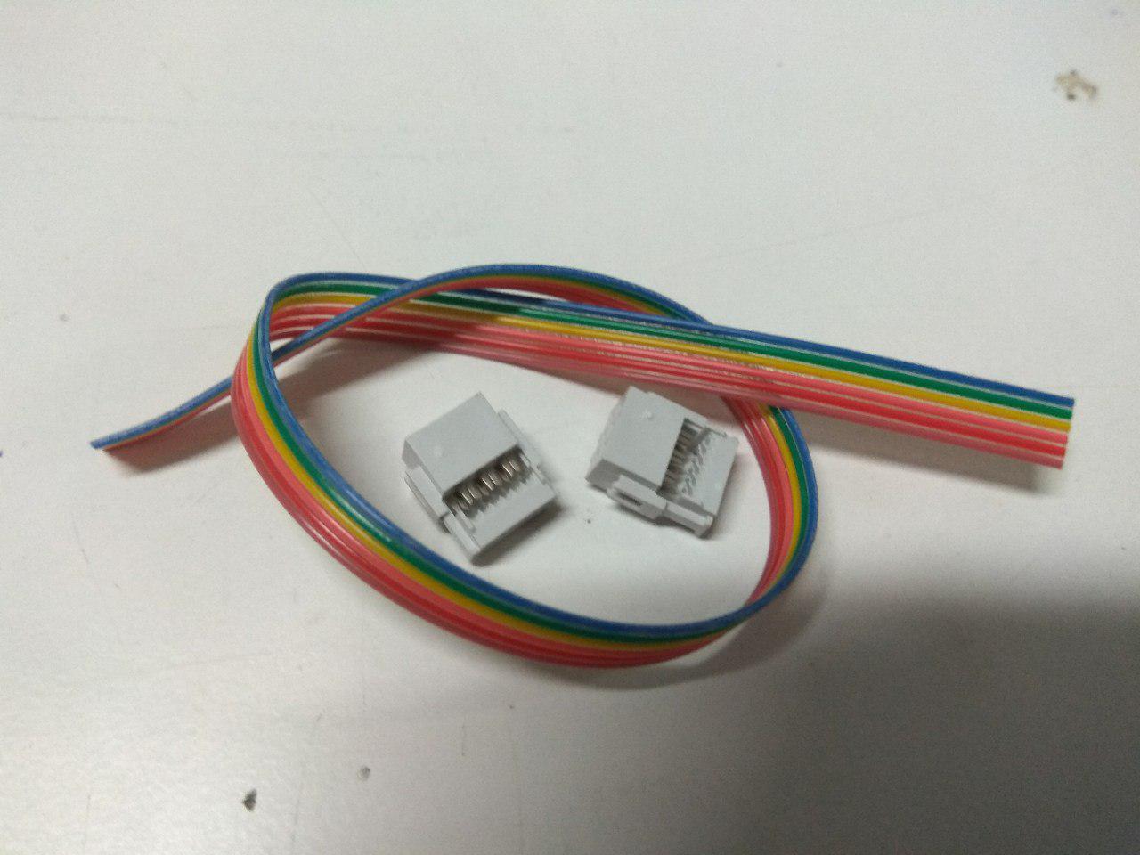
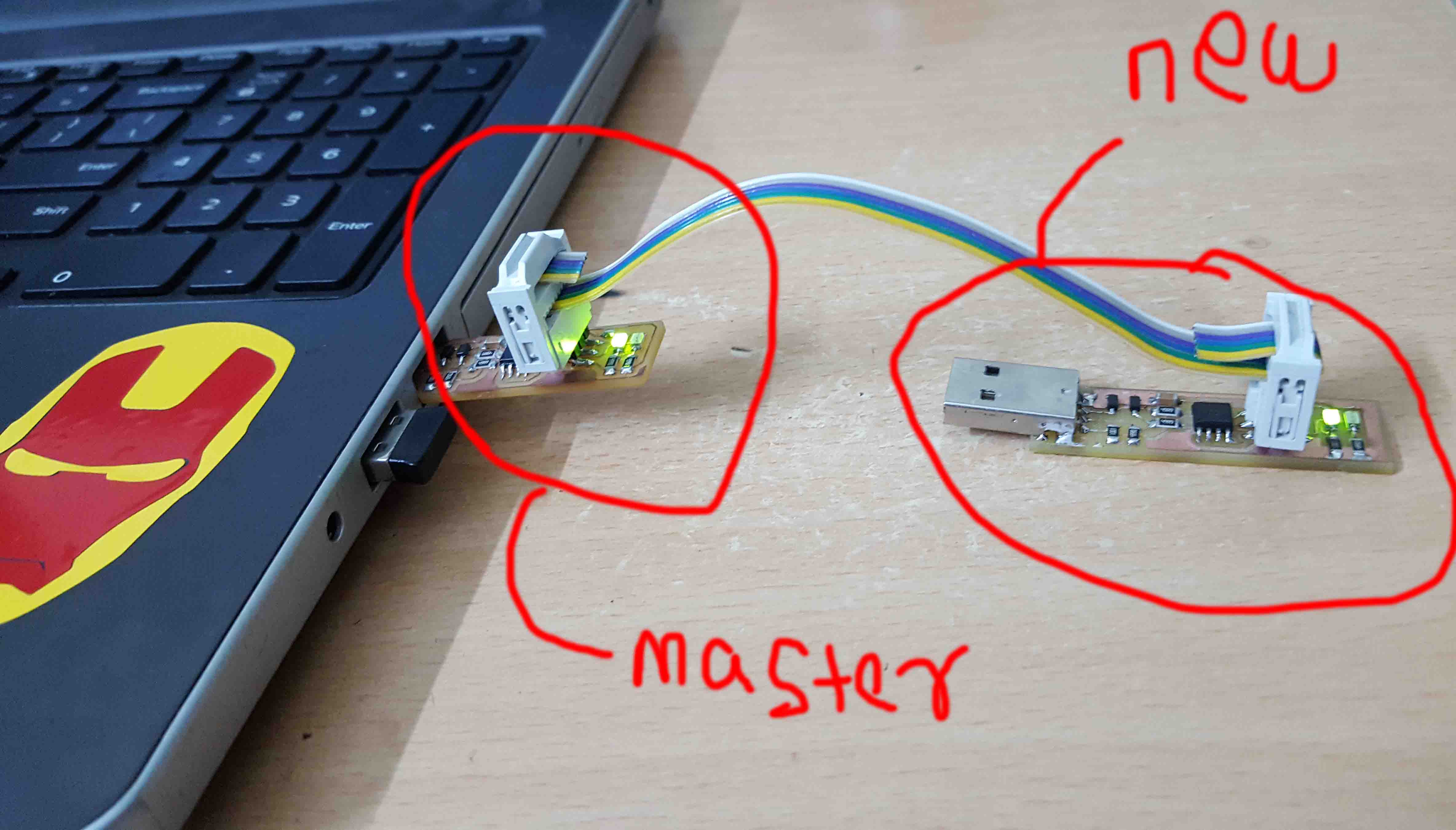
In heare i use previously build ISP to program new one. In previous case i use Arduino to program the ISP because we dont have any other programer. But in this time i have a programer so can easly flash fimwere on new ISP. At that case i use jumper wires, but in this case i make a FRC cable (6 wires).
Then just connect both isp together
I using Linux , so first we need to install avr-gcc tool-chain, type this on terminal to install tool-chian
sudo apt-get install avrdude gcc-avr avr-libc make
then Download fimwere from below
Download filesThen unzip the downloaded firmware and open terminal there.
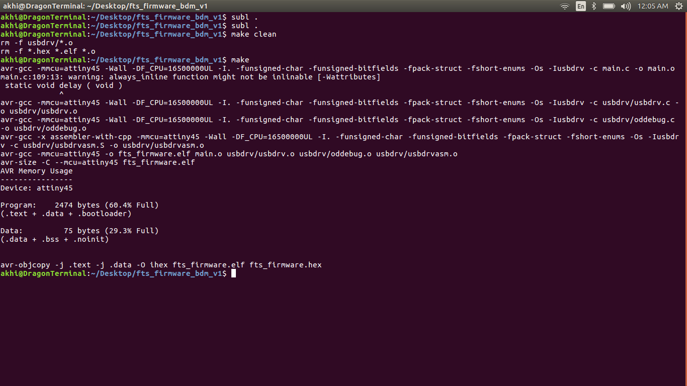
Now we can see the files , next we need to open the Makefile for ensuring it's configured for the ATTiny.i used nano to open the file , just typesubl . in terminal. which will open entire file in sublimetext
Now we can confirm that, it's configured for the ATTiny Before falshing make sure we are shorted the Progarmming Jumber on our PCB. and also make a Connector for ISP header,
Now we are ready to flash.
Type make clean clear previous data and make to colpile the firmware for new ISP.
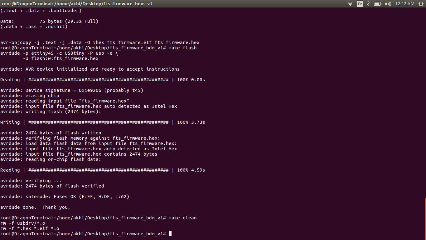
If everything is fine, Then make flash To flash new firmware to new ISP.
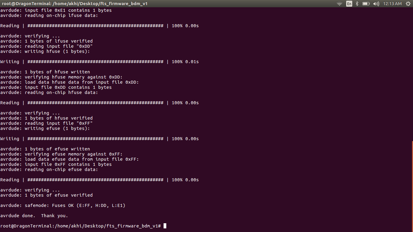
Now we are successfull flashed.We need activate the fuse in order to act our ISP as a progarmmer.For activating fuse make fuses it will automatically , activate the fuse.
we can desable reset by commad make rstdisbl it will actually disable the reset pin internally , once we done that we can't progarmmer the ISP board with new firmware.
Now we have the ISP Board
Testing New Isp
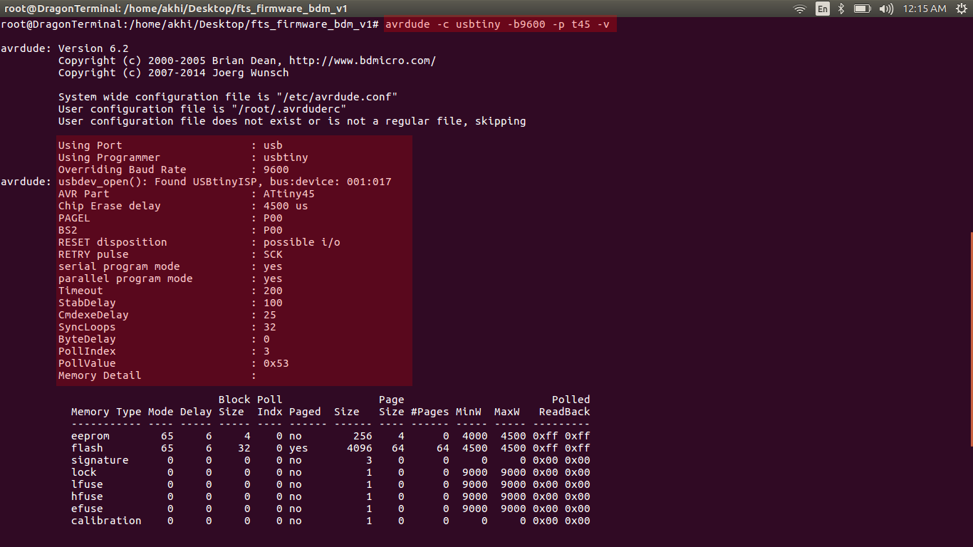
We need to test our New ISP is detected by the Computer or not. To do this open terminal again and enter the following cammand on it
avrdude -c usbtiny -b9600 -p t45 -v
Hero Shot
Group Assignment
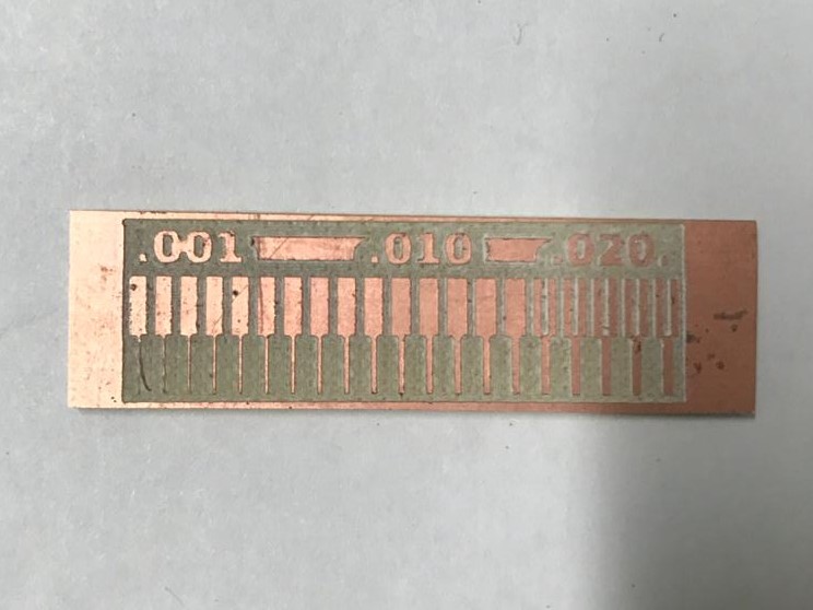
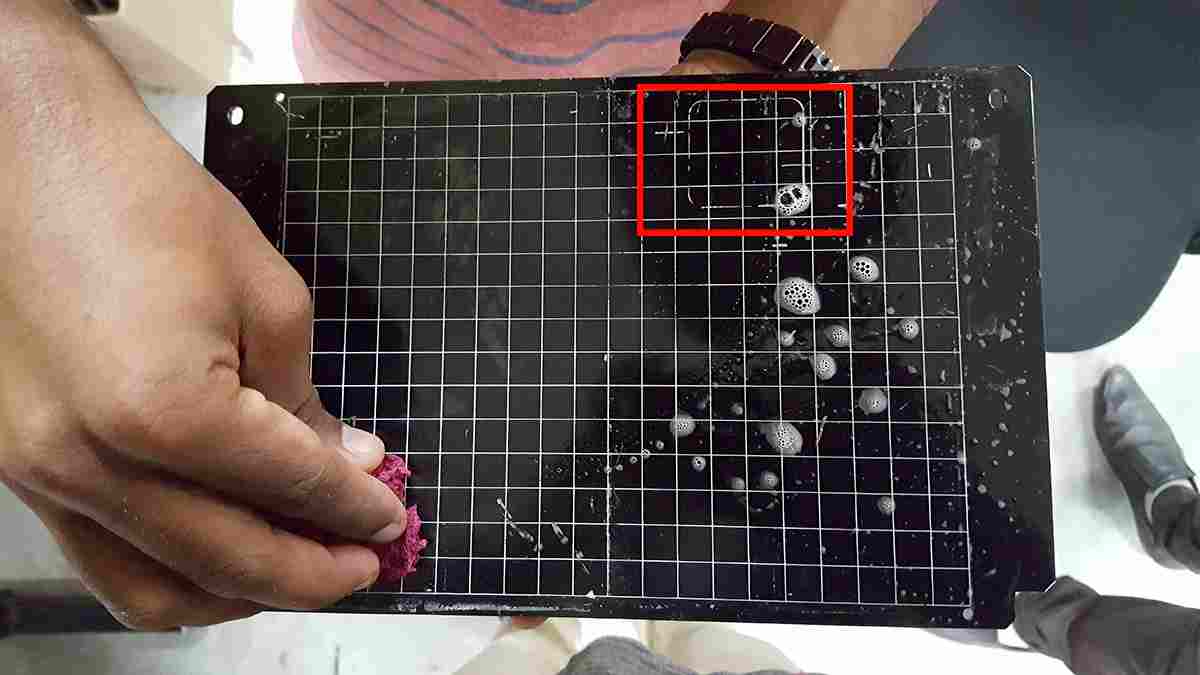
This Week we need characterize the specifications of our PCB production process i exaplined all procedure on the PCB Production section so next one is to find-out the how much resolution of 1/64 and 1/100 bit can mill and find out the difference.

This is our test pad , so let's mill it.first i tried with 1/64 bit ,
Finaly i got the PCB