Week 14: Networking and Communications
Group Assignment
Individual Assignment
Group Assignment
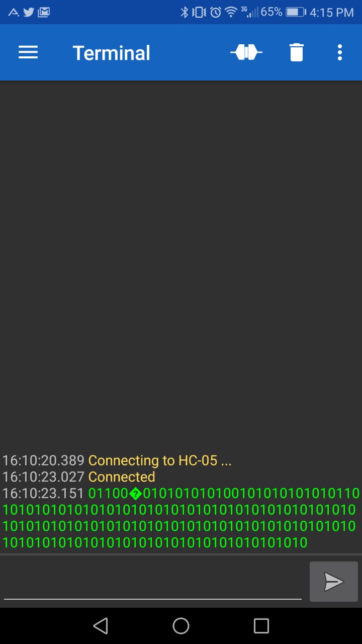
As a group assignment this week we used HC05 bluetooth module, connected it to atinny44. We then communicated with two slaves (slave 2 was atinny 44 with address 27 and slave 1 was atinny45 with address 26) making 328p the master. Hence led is blinking every time for one mili second. The reception of data can be seen below. Data here is just 0 and 1, and so led will just blink for 100ms.
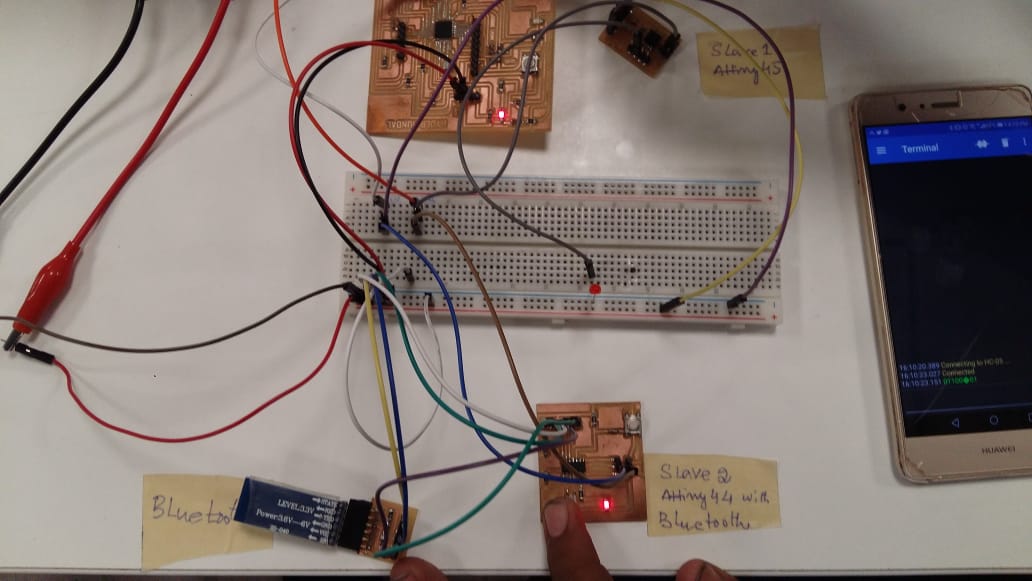
The attached video of circuitry illustrates working of network. It can be seen that Led on breadboard is attached to slave atinny 45 as it did't has any built in led.
Individual Assignment
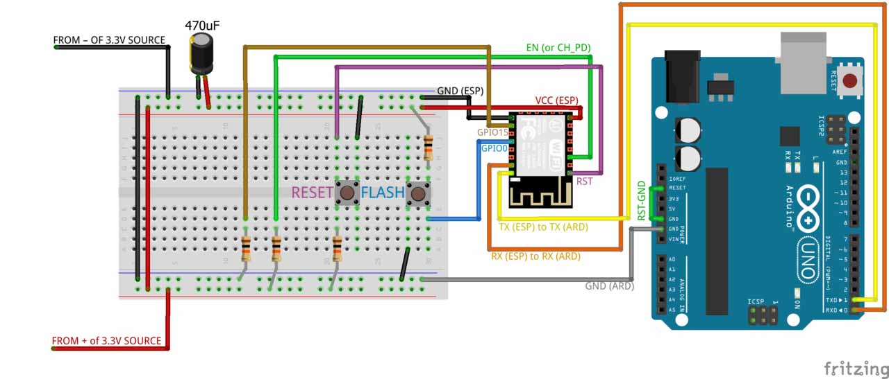
In this week of networking and communication I am working with wifi module ESP8266 (12E) which can be used for my final project. I'll use this module to receive the data i-e pattern or any analogue signal from cellphone/PC. Inorder to program this module it's mandatory to connect it's respective pin's to the arduino or any other board which is very hectic so for that I have another circuit which can be used for programming this board directly with ftdi cable. I followed each and every steps from this link
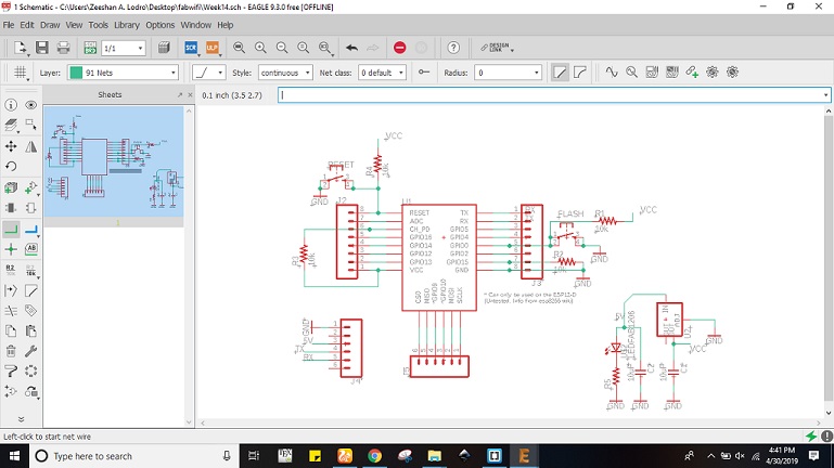
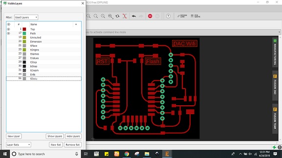
I designed the circuit in eagle software where I had to use the esp12e module, buttons, capacitors, resistors, LED and few headers. For that I used three libraries for headers I used Pin head library, for basic components I used fab library and for wifi module I used ESP8266 library. In order to connect them I used the following circuit diagram shown in (a) while picture (b) shows the schematic of my board and figure (c) shows traces of my wifi board where I hid all layers except few i-e top, pads etc.
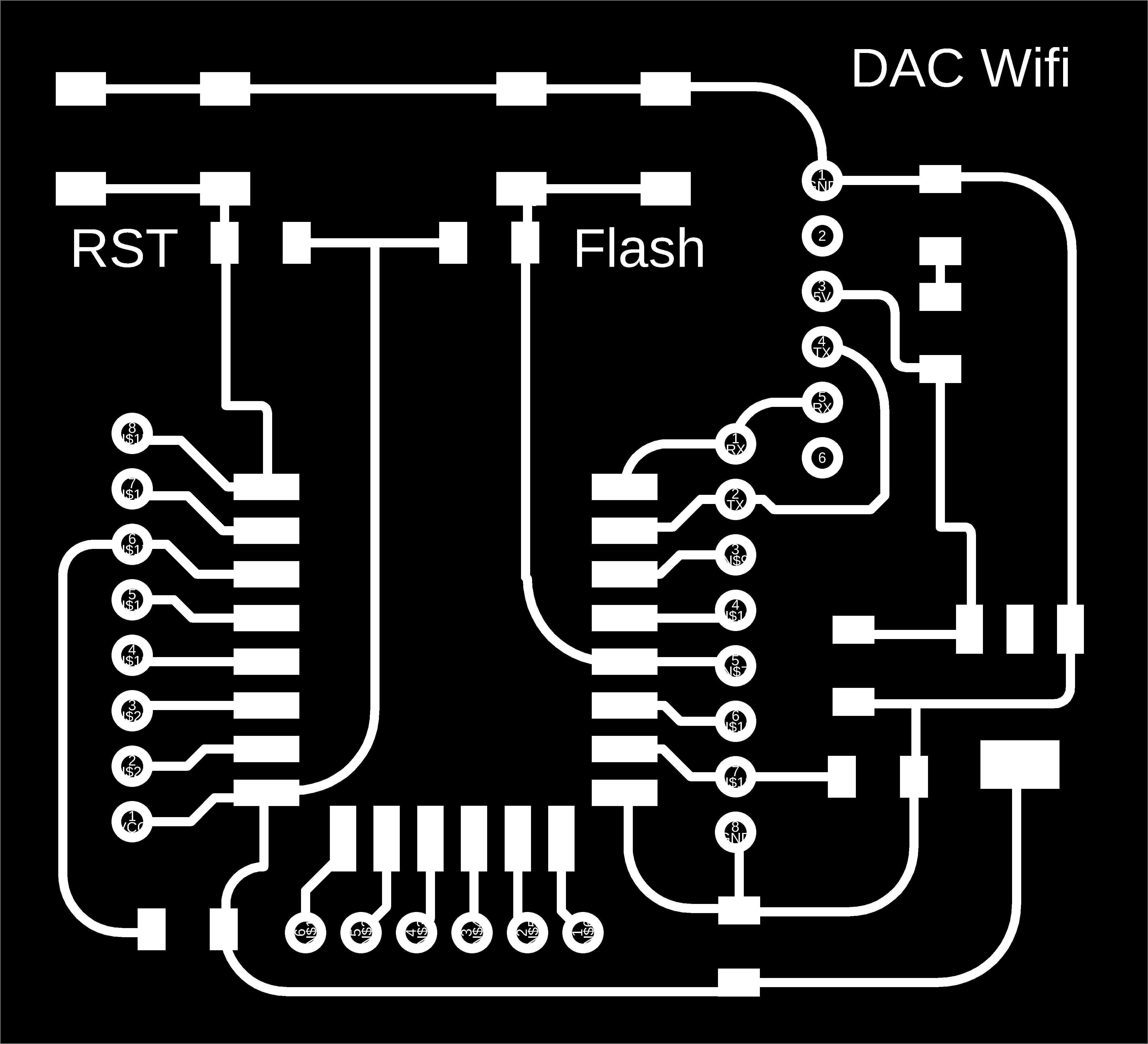
Later I exported the png monochrome image of ESP12E board with resolution 2000 dpi which can be seen in figure (a) and outline in figure (b) As this circuit uses through hole pin headers so I made drills as well which can be seen in figure (c).


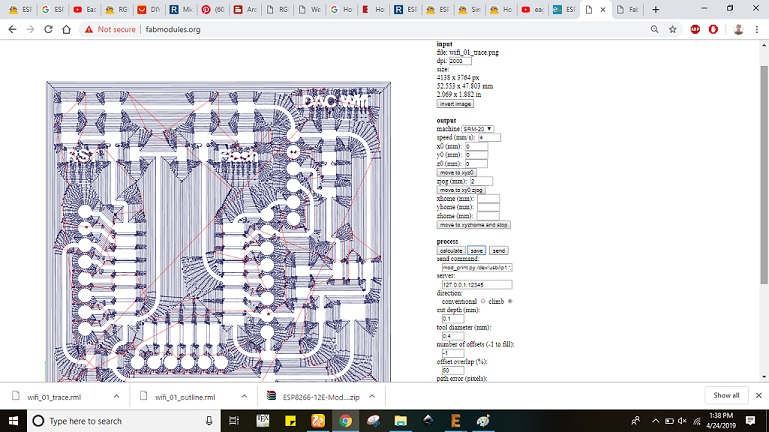
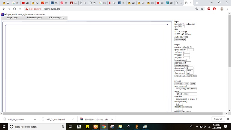
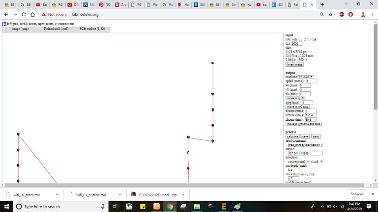
For rml generation I used fab modules which can be seen below. Figure (a) shows the rml generation of traces, figure (b) shows the rml generation of outline and figure (c) shows the rml generation of drills.
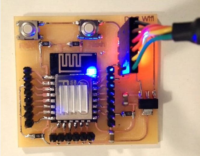
After milling the board I had to solder the components so for that I picked up following components from fab inventory and populated the board which is shown in figure (a).
1) ESP8266 (12E) module (01).
2) Resistors (10 Kilo Ohm =>04 and 499 Ohm => 01).
3) Capacitors (10 uf =>02).
4) LED (Orange colour).
5) SMD Header (1x8=>02) and (1x6=>02).
7) Push Buttons (02).
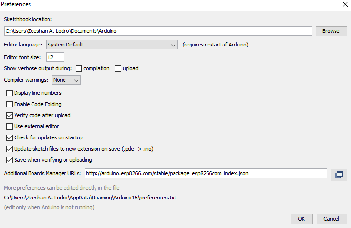
Before doing with programmig I had to include esp8266 libraray which I added as given =>File>Preferences>Additional Boards manager URLs: http://arduino.esp8266.com/stable/package_esp8266com_index.json , in Arduino IDE. Later I went to tools selected boards as node mcu 12e module and few other settings.
.png)
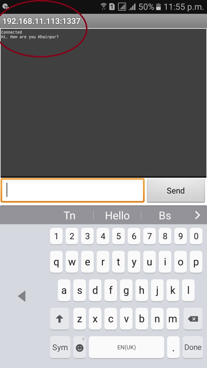
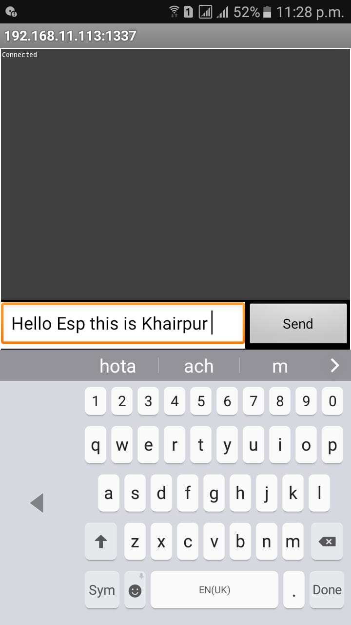
For networking and communication I tried to communicate between two wifi boards because it could be used in my final project part . For that I programmed given below program to the wifi board. This program will make my board as server and cellphone wifi as client. After that I tried to communicate between two esps by downloading the tcp client in cell phone. The figure right after programming shows that I am sending the string from cellphone and receiving that on esp12e board. The received message can be viewed from serial monitor of arduino ide.
#include ESP8266WiFi.h
const char* ssid = "FAB LAB";
const char* password = "fablab@iet";
const int ledPin = 4;
WiFiServer server(1337);
void printWiFiStatus();
void setup(void)
{ Serial.begin(115200);
WiFi.begin(ssid, password);
// Configure GPIO2 as OUTPUT.
pinMode(ledPin, OUTPUT);
// Start TCP server.
server.begin();
} void loop(void)
{
// Check if module is still connected to WiFi.
if (WiFi.status() != WL_CONNECTED)
{
while (WiFi.status() != WL_CONNECTED)
{
delay(500); }
// Print the new IP to Serial.
printWiFiStatus(); }
WiFiClient client = server.available();
if (client) {
Serial.println("Client connected.");
while (client.connected())
{
if (client.available()) {
char command = client.read();
Serial.print(command);
}
if (Serial.available() > 0) {
char incomingByte = Serial.read();
client.print(incomingByte);
}
}
Serial.println("Client disconnected.");
client.stop(); } }
void printWiFiStatus()
{ Serial.println("");
Serial.print("Connected to ");
Serial.println(ssid);
Serial.print("IP address: ");
Serial.println(WiFi.localIP()); }
The uploading methoding is not usual for this wifi board so it's really essential to take care of this thing while programming. Whenever an esp12e board is programmed you should press the flash button at the time when you see the uploading option in bottom left corner of arduino ide. By pressing the flash button you have to press the reset button single time and you see the programm is uploading. Now you can release the flash button. Furthermore the ssid, password and server/ port should be changed accordingly. Figure (a) shows the snapshot while uploading the program, figure (b) shows the snapshot when program is uploaded and figure (c) shows wifi board after program is uploaded.
.png)
.png)
In order get the ip address I opened the serial monitor of arduino ide and pressed reset button of wifi board which gave me an ip on serial monior can be seen below in figure (a). After getting ip I downloaded and installed the tcp client on smartphone where I provided the network name, IP and port which can be seen in figure (a). After that I sent some commands like strings and charchters which are shown below. I received those strings on esp12e board which can be seen on arduino ide serial monitor. The serial monitor image is shown in figure (b).
.png)
.png)
.png)