
Week 11: Input Devices
Group Assignment
Individual Assignment
Group Assignment
This week's group assignment was to detect the analogue and digital levels of input device we made individually so we started to measure the anlogue voltage levels of photo transitor which was used by me in this week's assignment. In group assignment we measured the voltage levels of this component which changes whenever we increase or decrease the intensity of lights on it. We connected the sensor module to 5 voltage and checked the output on data pin and ground using multimeter. We observed that whenever we increase the intensity of light voltages increase and whenever we decrease intensity of light voltage decrease. Both of the experiments are shown below in figures (a) and (b) respectively.


HC SR-04 Ultrasonic sensor is used by one of our group member in his individual task of this week so we used that sensor for detecting the digital signals. We have detected the change in digital signal in Oscilloscope using arduino Leonardo. A sensor is connected with arduino and the pin of Echo is connected with Oscilloscope. Arduino Leonardo is programmed to detect obstacle in front of Ultrasonic sensor, when an obstacle is present in front of Ultrasonic sensor we found change in wave in oscilloscope. The captured digital signal of ultrasonic sensor is shown below in figure. Furthermore the echo pin of sensor is connected to the pin 13 of leonardo which is also connected to led of board. The video given below shows that whenever there is change in signal led is blinking. The rate of led blink is very fast because digital signal is changing fastly.

Individual Assignment
As part of this week assignment I had to make board with any input sensor which shall take input like phototransistor, temperature sensor. As my project is related to leds so I tried to find something related to project like sound. I found two types of microphone adressed by neil. I started with one which was available at fab lab khairpur
- Up to 20dB of Gain
- Low Current
- Small package
- MaxRF protection
- Ultra-Stable Performance
- Omnidirectional

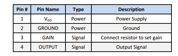
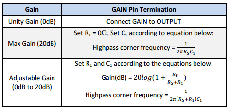
The Sisonic amplified analog microphone's interfacing circuitry is shown below in figure(a). It can be seen from figure below that mems microphone is attached with opam ic where capacitor and resistors are also used to set the gain of opam ic. The figure (b) shows thepin explaination of above circuit where it ca be seen that unity gain(0 dB) can be obtained by connecting gain directly to output, maximum gain(20 dB) can be obtained by setting R1 equal to zero and c1 equal to given high pass corner frequency equation however adjustable (0 to 20 db) gain can be obtained by setting R1 and C1 by given equations.

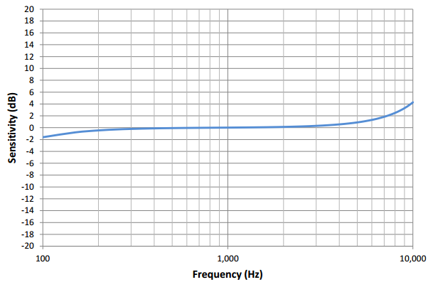
The sensitivity (dB) vs frequency response of SiSonic microphone is shown below in figure. The given response shows that microphone has almost constant sensivity of 0 dB over all frequency band. Furthermore it can also be seen that the sensivity suddenly rise after corner frequency of 10kHz and suddenly fall behind 100 Hz. Hence we can deduce that microphone works very well in the range of 100 Hz-10,000 Hz.
The below given figure shows the cross sectional view of the mems microphone metal can package where it can be seen that mems and IC are attached on base PCB and connected by wirebonds. Furthermore solder pads, port hole, and metal cap are also shown in cross sectional view of analog SiSonic microphone.

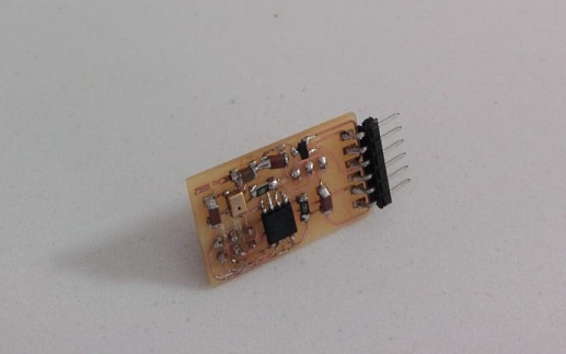
I designed the board of analogue mic in eagle software which can be seen below. I made this board to work as input and output like micorphone as input and rgb leds as output. For output I have added extra header of 3x1 which is used for leds. One pin shall be utilized for data in and two other are for VCC and ground. The designed board is shown below in figure.

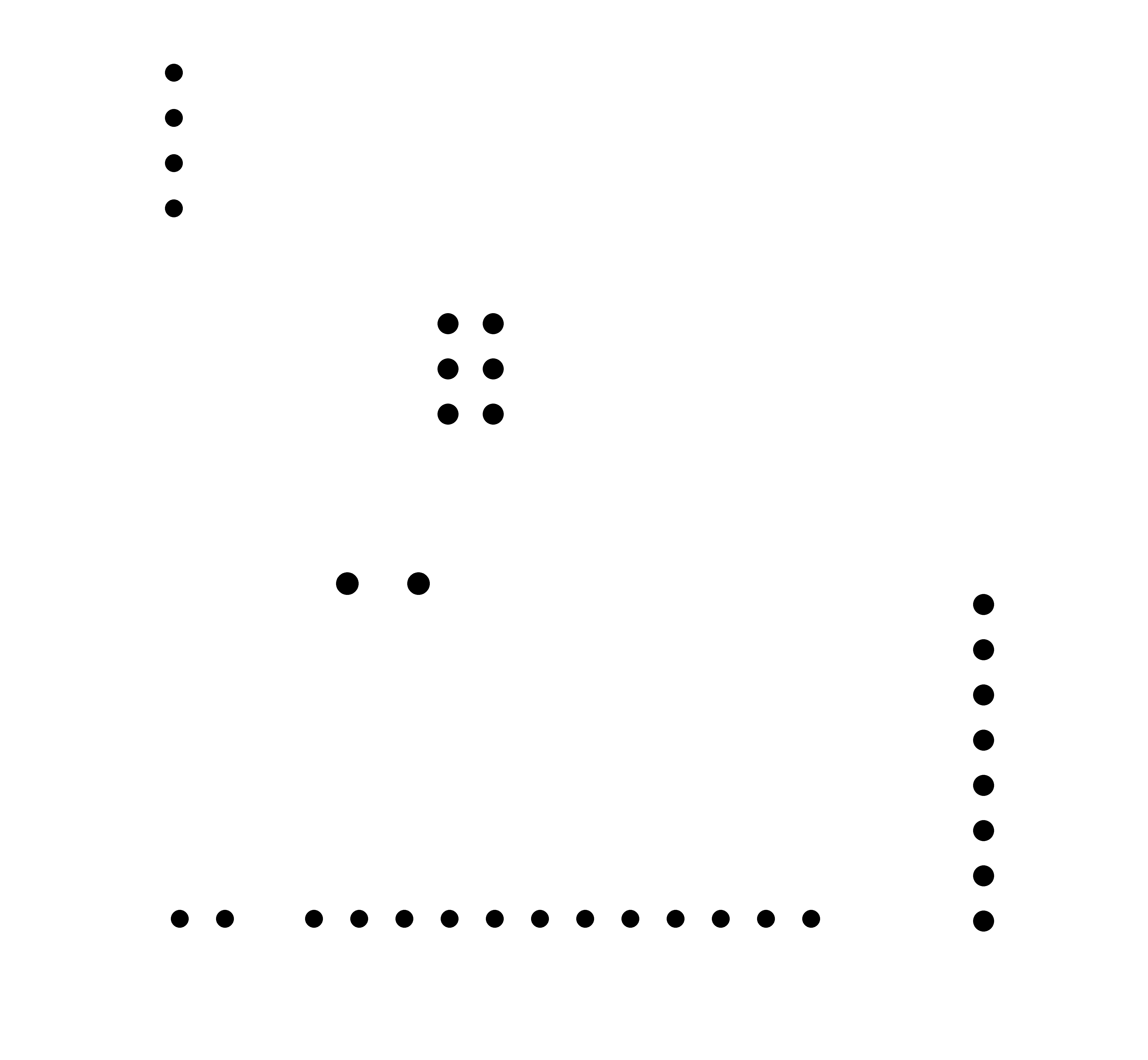
In order to mill the designed circuit I need png monochrome image with resolution of 2000 so exported that as png monochrom from eagle. The exported png image can be seen below. Figure (a) shows the taces png image, figure(b) shows the outline png image and figure (c) shows the drill holes monochromatic image.


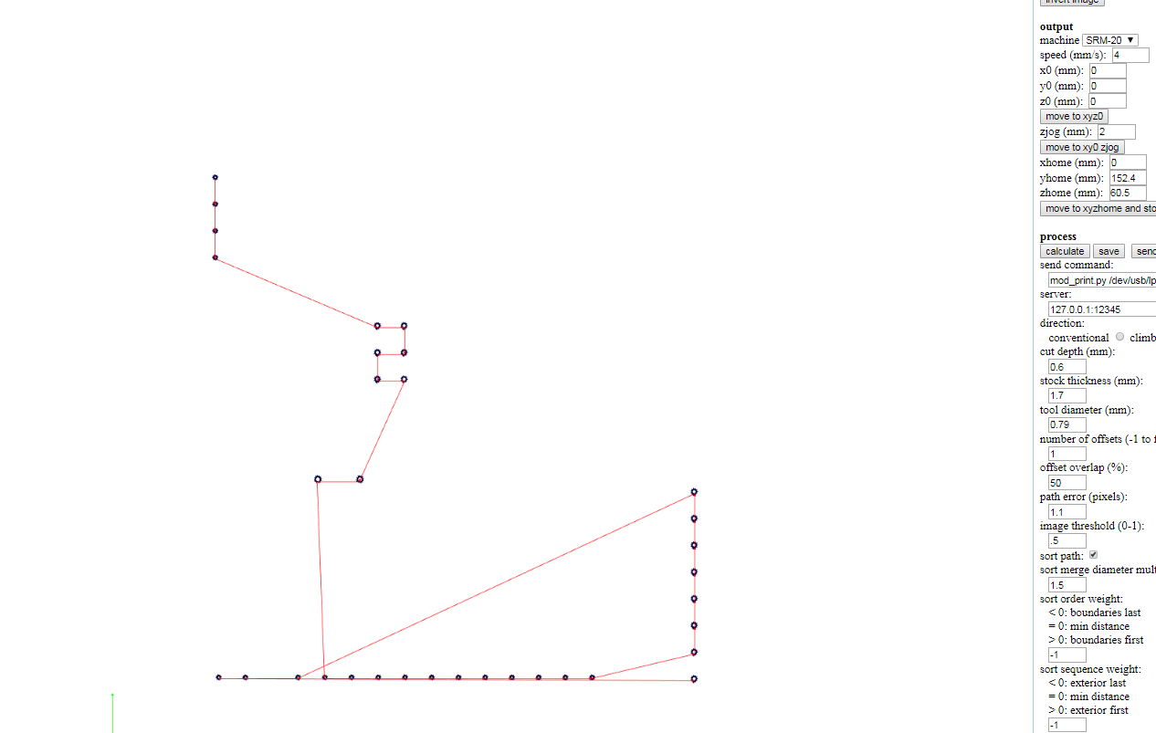
I followed the learnt process of generating path files. I did this using fab modules where I generated the rml files of traces , drill holes and outline. All of the images are shown below. figure (a) shows the rml generation of traces,figure (b) shows the rml generation of outline and figure (c) shows the rmls of drill holes used in the designed board.

.png)

1) Attiny 45 (01).
2) Resistor (10 Kilo Ohm =>01 and 1 Kilo Ohm => 01).
3) Capacitor (10 uf)=01 and Capacitor (1uf)=03.
4) IC regulator 3.3V
5) SMD Header (6 pin).
6) ISP header (6pin) through hole
7) Header 3x1 through hole.
8) Analogue micorphone
I soldered this board but this did not worked. Since I was unsure in soldering so I resoldered this board that's why the soldering is bumpy and bad. I think I wasted much time just to make this mic work so I tried to take the mic out and check with arduino.
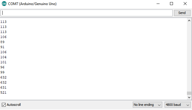
It went well with arduino. The figure (a) shows the code which I used for microphone and and the figure (b) shows the arduino output on serial monitor where it can be seen that values are continuously changing and figure (c) shows the led blinking with tune.
.png)

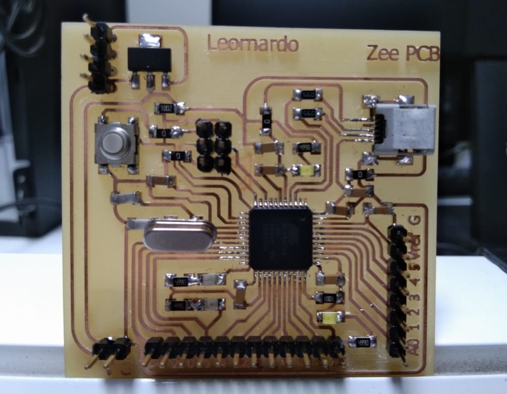
In order to cover input, output assignment and final project I am designing this generic pcb board. For that I chose Atmega328u microcontroller which I will be using onwards. From begining I am using eagle software for designing of pcb boards therefore I will also use eagle for this board. For arduino leonardo circuit design I have followed my instructur's webpage i-e Suhail Ahmed Soomro. The designed boards Schematics, traces, outline and drills are shown in below figures respectively.
_2.png)


After getting the traces, outline and drills I had to generate rml files which is given to SRM20 machine. For that I used fab modules which generates rml files of given monochrome png image. In figure (a) rmls of traces are shown, in figure (b) rmls of outlines are shown and in figure(c) the rmls of drills are shown. we shall keep in mind that drill bit 1/64 should be chosen for traces and 1/32 should be chosen for both outlines and drills. Also make sure you should use drills rmls first and outlines rmls second.

_2.png)

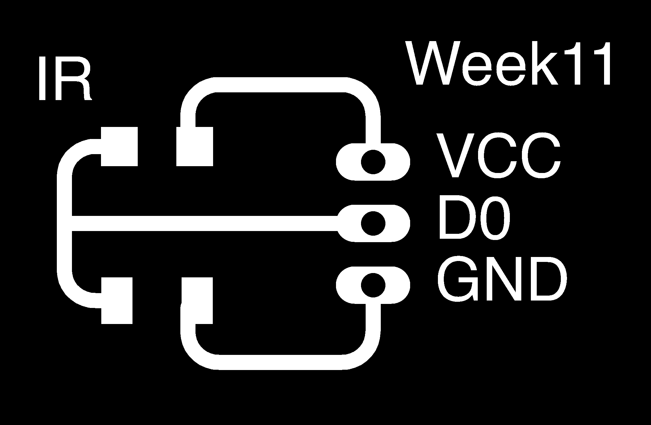
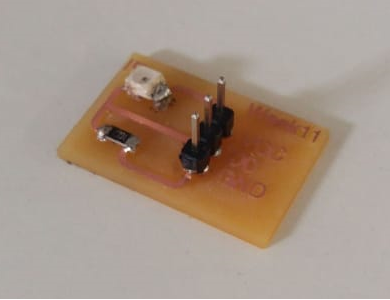
Now I have taken photo transistor sensor which reacts to light. Firstly I made this module in eagle software which can be seen in given figure. The outline, drills and module are also shown below in figures. After doing that I did some analogue programming which is mentioned in programming section. In last there is video which shows that whenever I am changing the intensity of light I am getting the change in embeded led of arduino leonardo.


const int analogInPin = A0;
const int analogOutPin = 13;
int sensorValue = 0;
int outputValue = 0;
void setup() { Serial.begin(9600);
}
void loop()
{
sensorValue = analogRead(analogInPin);
outputValue = map(sensorValue, 0, 1023, 0, 255);
analogWrite(analogOutPin, outputValue);
Serial.print("sensor voltage level = ");
Serial.print(sensorValue);
Serial.print("\t LED output = ");
Serial.println(outputValue);
delay(100);
}