Group Assignment: Characterize your lasercutter making test parts that vary cutting settings and dimensions.
In this week first had to do kerf measurement so that when we cut our press fit kit, it fits in perfectly. Kerf is the size of blade cutting your material, that in our case is laser. Laser cutter cuts our designs on borders hence our cutted design gets some addition/error of around 0.1,2,3.. mm which looses the design hence press fit is not like the perfect press fit. For this week we are using cardboard, it does not have this issue because it can be pressed and adjusted but when it comes very solid and hard materials press fit designs get very ugly if kerf is considered. Hence what we need to do is to first identify the kerf in mm and then subtract thhe kerf from our material thickness so that laser cuts from inwards our design to borders rather cutting it on borders and outwards.
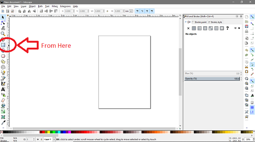
So we made a very simple design in inkscape to measure kerf. We made a rectangle as shown below. Click as shown below and make a rectangle by clicking on screen and then dragging around.
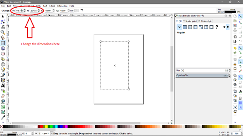
Next, We adjust the dimensions of rectangle as shown below. Write your desired dimensions in H (Height), and W (Width) bars.
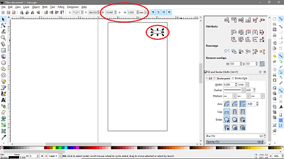
Next we made another rectangle smaller in dimensions with 3.5mm of height, and around 7 mm of width. Note: Here this smaller rectangle's height is the thickness of material/cardboard and that is around 4mm.
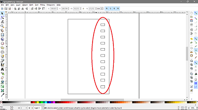
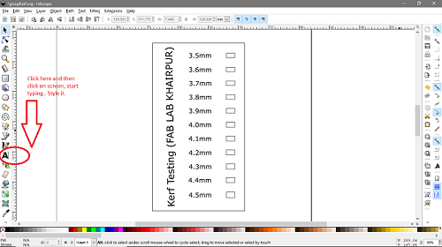
Hence we made 11 of these small rectangle with varying heights from 3.5mm to 4.5mm. What we will do is check which one of these 11 rectangles has perfect height of 4mm.
Now, we just pasted some text by dragging down the text bar. Once clicked the text bar > click anywhere on the screen. Now start writing > Now style it. and That is it..
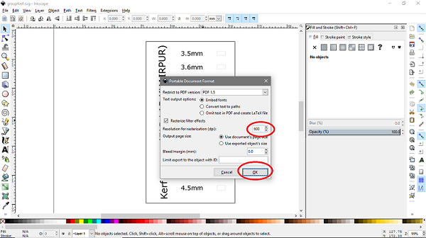
Set stroke to 0.001inch for cut Now save file as a .pdf > while saving file as a pdf it system will open a dialog window, asking for dpi (dots per inch) you need to set it to 600 and click ok.
Next open the pdf file and click printter icon > select your machine (epilog) and click print.

So next open epilog here you can see in jobs that the pdf file we sent has appeared in the list. Now first go to preview by clicking on preview. and verify that raster stuff does not appear in vector mode and vise versa. Now for print press combined and next characterize the machine as following. and click printer icon

Now run the machine, and check if machine has received your job or not.

Yup. It has received our file so click the button go and leave it to machine now..
That is it. Our file is ready.
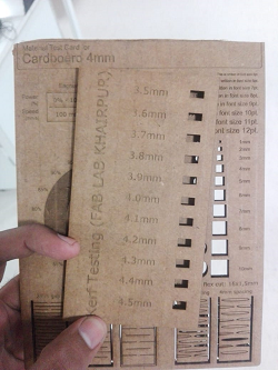
Now if you see following 2-3 images only one of them illustrates a perfect fit, and that is with 3.8mm of thickness. Hence we observe that, kerf here is (4mm-3.8mm=0.2mm)/2 so kerf = 0.1mm.

Rest of them will be loose as they have greater thickness..
Continuing the group assignment we also printed this material test card using the same laser cutting machine by repeating last few steps to operate the machine.

Individual Assignment: Cut something on vinyl, and make a parametric press fit construction kit.
This individual assignment included opertaing two machines - vinyl and laser cutter.
I started with vinyl and i cutted Minaar-e-Pakistan. Minaar-e-Pakistan is a 70m tall symbolic tower here in pakistan built to commemorate the Pakistan day. We celeberate 23rd march as Pakistan day, because on this date back in 1940 pakistan resolution was passed.
I first downloaded an image..
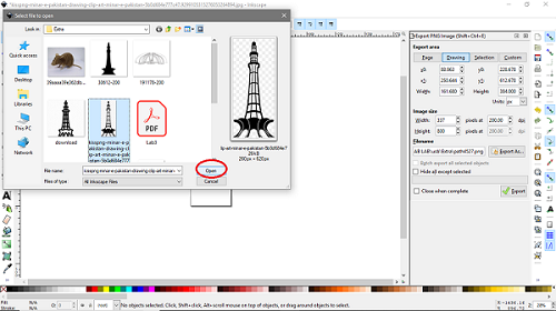
Now open inkscape > go to file > open the image you want to cut on vinyl.

Select the image and click open or drag it to inkscape screen. Once you clicked ok, a dialog box will appear with default settings you need to do nothing here and just press ok.
Now once you have your image opened in inkscape. Go to path and select trace bit-map. you can also use shorcut key appearing infront of the option.

Now click on live preview and vary the thresholds. With live preview you will see image being traced in the run-time while adjusting the thresholds.. Adjust the thresholds that best suit you your image and click ok.

Here just click on the traced image and drag it away from the original one. This image is the vectored one with very high resolution.

Now delete original image and export the vectored image > give a path to it and click export.

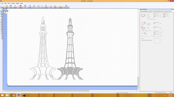
Now first open the exported png image with paint and save it again but as a jpg image. Let's go to machine now. First open roland cutstudio software on your PC and open image that you want to cut in jpg format.

Now right click on image > and select image outline. Here following window pops up. Now click on extract contour lines as following and then ok.

Click on the image and drag around the contoured image.
Now click on cutting adjust the width and height of your vinyl sheet (if applicable) and go

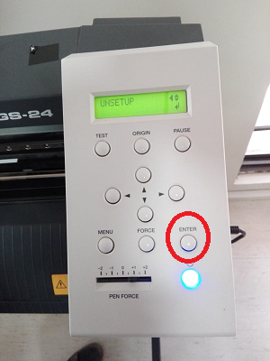
Now power on the machine and select roll.
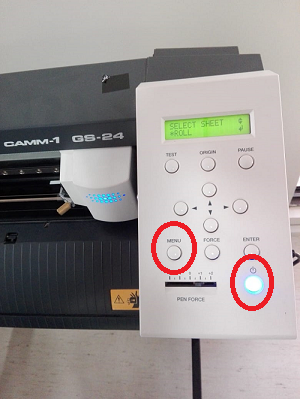
Now press menu button twice and enter. So our machine starts cutting.
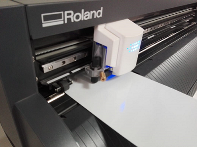 There are some parameters worth a mention, like the force/pressureapplied to cut the vinyl. Following you see them on machine, this is to what value i adjusted them.

Next, We first took the unwanted part off > then pasted on transfer paper > pasted image on my laptop > took off the transfer paper and tan tara, that is it i have it my laptop now.


Next, We move to 2nd assignment that is on laser cutter.
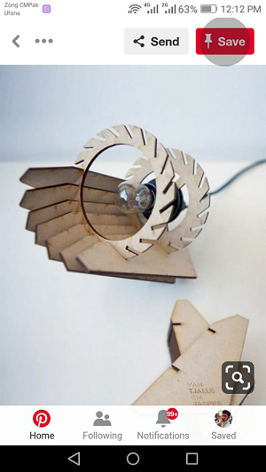
First open solidworks and make a parametric design. I saw following lamp on pinterest and started working on it.
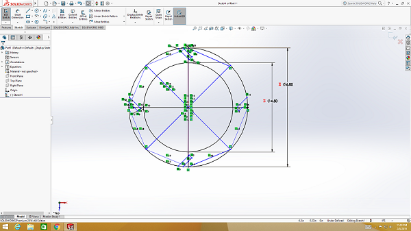
 First i made following sketch. Started with two circles and then cutted it. But it had problem as i mirrored the cut hence the copies were opposite in direction.
 Now we get following result by extruding the circle > and then taking extrude cut for once.
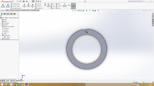 Thanks to solidworks you dont need to do alot. Just go to pattern > select circular pattern > select extrude cut > then select direction you want pattern in-(by selecting circle) next just define number of copies needed also specify the degrees in between two copies.
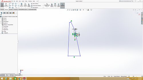
 That was it. First part is ready. Now lets move to next part where we started with rectangle and then ended up in our sketch for part2.

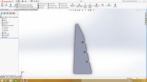
 Now i just made the part to be cutted and then again used pattern to copy files. Selected linear pattern this time > then selected extrude cut part (to be copied) > then for direction selected the line that has cut > specified copies > and distance in between copies. that is it.
 Now i tried assembly as following in soildworks.
 Next, we need to convert these .sldprt into .dxf because dxf files can then be imported into inkscape. To do so open new assembly/part file in solidworks and import the part1 and part2 individually.
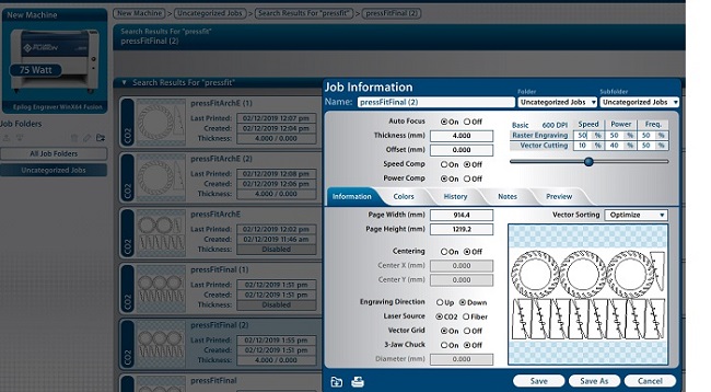
Save these files as .dxf and import them to inkscape, place them nicely on an arch e sheet. Now repeat the steps from group assignment by making a pdf file and then going to machine and setting power and speed values as following.
Next, we need to convert these .sldprt into .dxf because dxf files can then be imported into inkscape. To do so open new assembly/part file in solidworks and import the part1 and part2 individually.
Save these files as .dxf and import them to inkscape, place them nicely on an arch e sheet. Now repeat the steps from group assignment by making a pdf file and then going to machine and setting power and speed values as following.

 That is it. We have our press fit construction kit ready.
 Click here to get design files..

This work is licensed under a Creative Commons Attribution-ShareAlike 4.0 International License
Copyright © 2019 Azmat Hussain
Individual Assignment: Cut something on vinyl, and make a parametric press fit construction kit.
This individual assignment included opertaing two machines - vinyl and laser cutter. I started with vinyl and i cutted Minaar-e-Pakistan. Minaar-e-Pakistan is a 70m tall symbolic tower here in pakistan built to commemorate the Pakistan day. We celeberate 23rd march as Pakistan day, because on this date back in 1940 pakistan resolution was passed.
I first downloaded an image..
Now open inkscape > go to file > open the image you want to cut on vinyl.
Select the image and click open or drag it to inkscape screen. Once you clicked ok, a dialog box will appear with default settings you need to do nothing here and just press ok.
Now once you have your image opened in inkscape. Go to path and select trace bit-map. you can also use shorcut key appearing infront of the option.
Now click on live preview and vary the thresholds. With live preview you will see image being traced in the run-time while adjusting the thresholds.. Adjust the thresholds that best suit you your image and click ok.
Here just click on the traced image and drag it away from the original one. This image is the vectored one with very high resolution.
Now delete original image and export the vectored image > give a path to it and click export.
Now first open the exported png image with paint and save it again but as a jpg image. Let's go to machine now. First open roland cutstudio software on your PC and open image that you want to cut in jpg format.
Now right click on image > and select image outline. Here following window pops up. Now click on extract contour lines as following and then ok.
Click on the image and drag around the contoured image.
Now click on cutting adjust the width and height of your vinyl sheet (if applicable) and go
Now power on the machine and select roll.
Now press menu button twice and enter. So our machine starts cutting.
There are some parameters worth a mention, like the force/pressureapplied to cut the vinyl. Following you see them on machine, this is to what value i adjusted them.
Next, We first took the unwanted part off > then pasted on transfer paper > pasted image on my laptop > took off the transfer paper and tan tara, that is it i have it my laptop now.
Next, We move to 2nd assignment that is on laser cutter. First open solidworks and make a parametric design. I saw following lamp on pinterest and started working on it.
First i made following sketch. Started with two circles and then cutted it. But it had problem as i mirrored the cut hence the copies were opposite in direction.
Now we get following result by extruding the circle > and then taking extrude cut for once.
Thanks to solidworks you dont need to do alot. Just go to pattern > select circular pattern > select extrude cut > then select direction you want pattern in-(by selecting circle) next just define number of copies needed also specify the degrees in between two copies.
That was it. First part is ready. Now lets move to next part where we started with rectangle and then ended up in our sketch for part2.
Now i just made the part to be cutted and then again used pattern to copy files. Selected linear pattern this time > then selected extrude cut part (to be copied) > then for direction selected the line that has cut > specified copies > and distance in between copies. that is it.
Now i tried assembly as following in soildworks.
Next, we need to convert these .sldprt into .dxf because dxf files can then be imported into inkscape. To do so open new assembly/part file in solidworks and import the part1 and part2 individually.
Save these files as .dxf and import them to inkscape, place them nicely on an arch e sheet. Now repeat the steps from group assignment by making a pdf file and then going to machine and setting power and speed values as following.
That is it. We have our press fit construction kit ready.
Click here to get design files..
This work is licensed under a Creative Commons Attribution-ShareAlike 4.0 International License
Copyright © 2019 Azmat Hussain