Week#13
Networking and Communications
The group tast of this week is to send a message between two projects or microcontrollers.
As a group assignment this week we used HC05 bluottoth module, connected it to atinny44. We then communicated with two slaves (slave 2 was atinny 44 with address 27 and slave 1 was atinny45 with
address 26) making 328p the master. Hence led blinking every for one mili second shows the reception of data. Data here is just 0 and 1, and so led will just blink for 100ms. Connection can be
seen below.
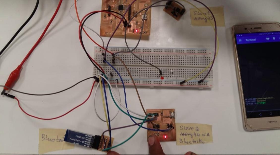
Next we used terminal as to see data received.
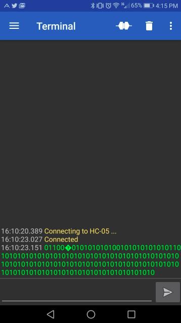
Below attached video illustrates working network. Note: Led on breadboard is attached to slave atinny45 as it didn't have any built in led.
The individual tast of the week is to Design and build a wired and/or wireless network connecting at least two processors.
As part of this week's assignment, I need to make a network either wired or wireless by connecting atleast two microprocessors together.For this I am
following I2C method to communicate different microcontrollers at same time.
I have decided to use the boards that I had designed in my previous weeks.
One I am using a Atmega328 board(I have designed this board for my final project) and 2nd board that I have designed in the
Input Week ATtiny44 generic Board)
and 3rd board is the
6th week Echo Hello board(ATtiny44).
I am following I2C method to communicate different microcontrollers at same time. In I2C method of communication of devices we can communicate
devices through serial computer bus. This is pronounced as I2C (I squared C), or I2C (I two C), or IIC (Inter-Integrated Circuit). The I2C bus
communication is broadly used in many electronic devices because it can be easily implemented in circuits where communication between devices is required.
In this method a master board and different slaves board or multiple master communicate simaltaneousy. This method allows communication between
upto 112 slave devices when using 7-bit addressing, and 1008 devices while using 10-bit addressing.
Only two wires are used of each device to be common. These two wire are SDA(Serial Data Line) and SCL (Serial Clock Line). Where the SCL line
is the clock signal which synchronize the data transfer between the devices on I2C bus, and it is generated by the master device. And, SDL line's
function is to carry the data.
First I used two boards one Atmega328 as master board and ATtiny44 generic board as a slave board.
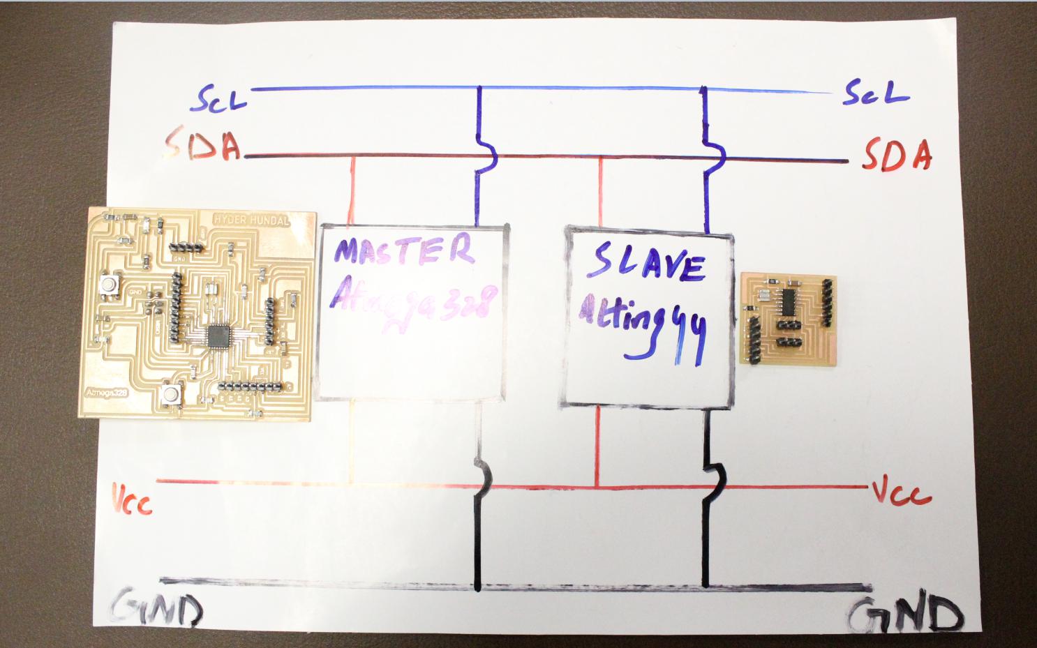
I followed this architecture design to allow devices to communicate.
Actually My ATtiny44 geneic board was completely damaged so for I made another one.
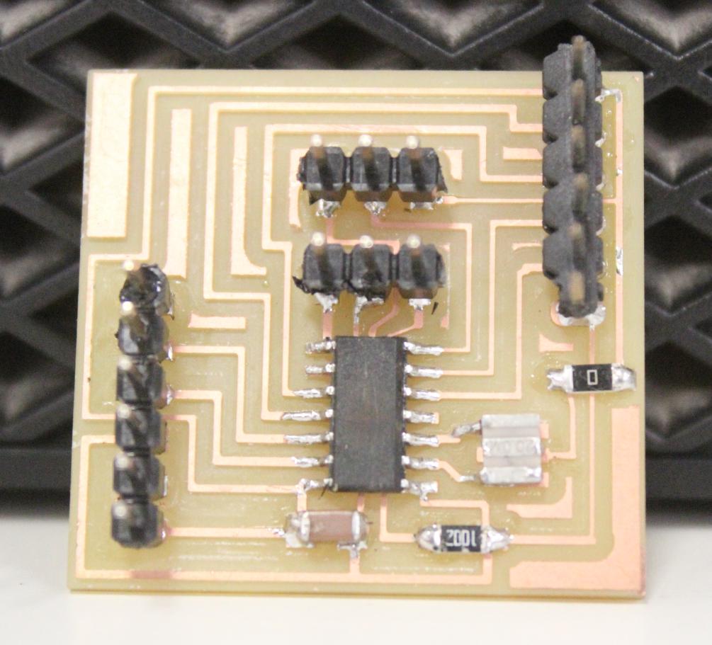
ATtiny44 board
My Atmega328 board for the final project
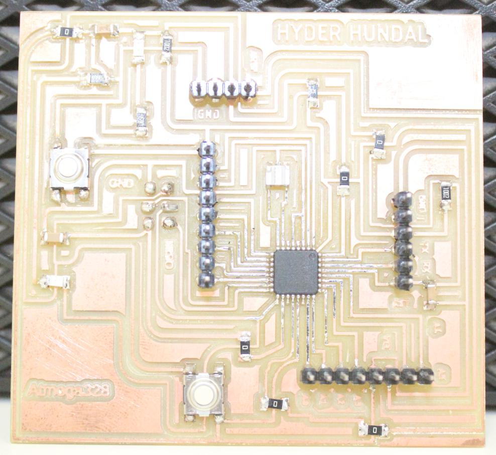
Atmega328 board
I made Connection of SDA, SCL on breadboard for serially I2C communication between one Slaves and one Master. for this first I defined my SDL and SCL pins
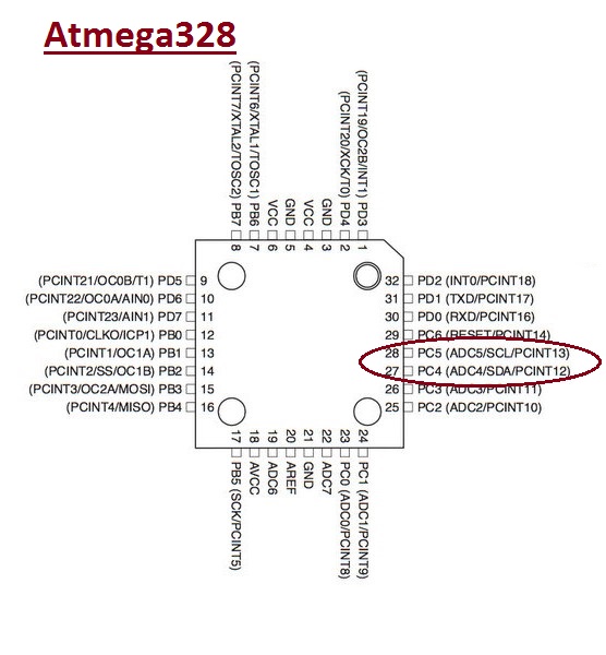
SCL and SDL of Atmega328
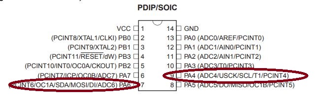
SCL and SDL of ATtiny44
For source code of slaves and master, I explored the fab academy website and found my required source, then I modified the source bit according
to my scenario. There are several libraries in arduino which supports this communication. For Master, I downloaded and installed Wire library, and for
slaves I downloaded and installed tinywireS library. Without installing these libraries I was unable to upload the code to the devices, so, one must
do these pre-requisite things to be on safe side.
I looked up the Fabacademy website and found some implementation of i2c transmission systems. The links are provided here:
Muhammad Asim
Massimiliano Dibitonto
Code for Master board:
#include "Wire.h"
void setup()
{
Wire.begin(); // join i2c bus (address optional for master)
}
void loop() {
Wire.beginTransmission(0x26); // transmit to device #26
Wire.write(0x00); // sends one byte
Wire.endTransmission(); // stop transmitting
Wire.beginTransmission(0x27); // transmit to device #27
Wire.write(0x00); // sends one byte
Wire.endTransmission(); // stop transmitting
delay(2000);
Wire.beginTransmission(0x26); // transmit to device #26
Wire.write(0x01); // sends one byte
Wire.endTransmission(); // stop transmitting
Wire.beginTransmission(0x27); // transmit to device #27
Wire.write(0x01); // sends one byte
Wire.endTransmission(); // stop transmitting
delay(2000);
}
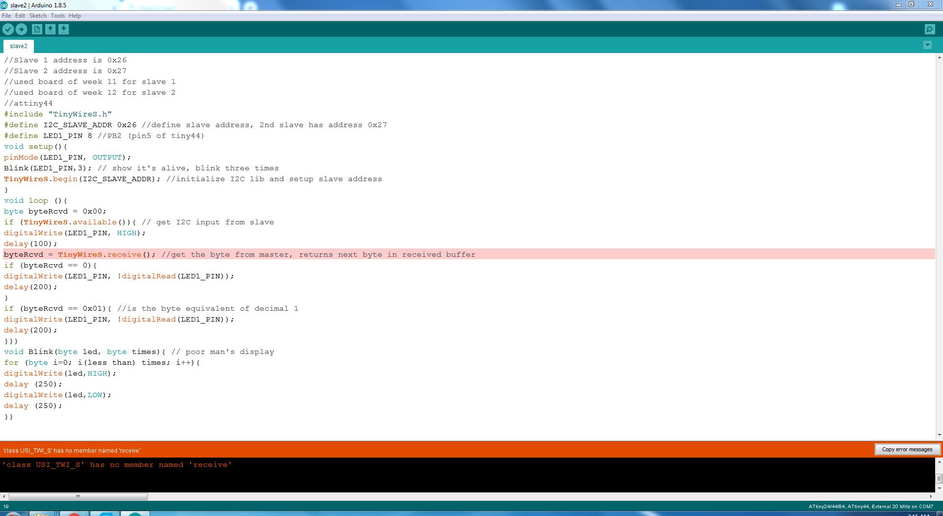
Code for Slave boards:
//Slave 1 address is 0x26
//Slave 2 address is 0x27
//used board of week 11 for slave 1
//used board of week 12 for slave 2
//attiny44
#include "TinyWireS.h"
#define I2C_SLAVE_ADDR 0x26 //define slave address, 2nd slave has address 0x27
#define LED1_PIN 8 //PB2 (pin5 of tiny44)
void setup(){
pinMode(LED1_PIN, OUTPUT);
Blink(LED1_PIN,3); // show it's alive, blink three times
TinyWireS.begin(I2C_SLAVE_ADDR); //initialize I2C lib and setup slave address
}
void loop (){
byte byteRcvd = 0x00;
if (TinyWireS.available()){ // get I2C input from slave
digitalWrite(LED1_PIN, HIGH);
delay(100);
byteRcvd = TinyWireS.receive(); //get the byte from master, returns next byte in received buffer
if (byteRcvd == 0){
digitalWrite(LED1_PIN, !digitalRead(LED1_PIN));
delay(200);
}
if (byteRcvd == 0x01){ //is the byte equivalent of decimal 1
digitalWrite(LED1_PIN, !digitalRead(LED1_PIN));
delay(200);
}}}
void Blink(byte led, byte times){ // poor man's display
for (byte i=0; i(less than) times; i++){
digitalWrite(led,HIGH);
delay (250);
digitalWrite(led,LOW);
delay (250);
}}
I used this code and got some errors, and this was the main error during all these for me.
After searching for solution I tried different thing and then my local Instructor
Sohail Soomro guided me, and I chnage statement Receive into Read and solved the problem.
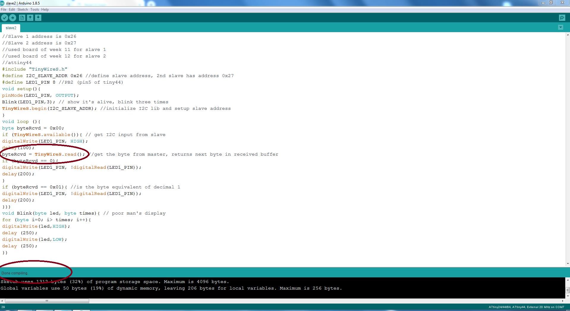
Finally I successfully upload the boath master and slave code.
One Master One Slave.
After one one master and one slave I made some changes and and another board of ATtiny44 Heloo world board, and made One master(Atmega328) and made two
slaves(ATtiny44 generic and Echo hello world board).I used the same code for the 2nd slave just addressed it in the master and slave code. As shown in
the cooding comments.