3. Computer-Aided Design
This week I used a bunch of different tools to digital-design my final project.
Inspirations and Aspirations
2D
Adobe Illustrator (AI)
I used Illustrator once before, and although I didn’t find it difficult, I thought it was a little bit intimidating, because you can do a lot of complex things with it, but I am very interested in learning to use it to make illustrations and diagrams. So my approach with Illustrator is making a sticker out of a photo from the 1.0 version of my console, P_A+L!, so I could fabricate and vinyl cut this sticker next week, when we see Computer Controlled Cutting.
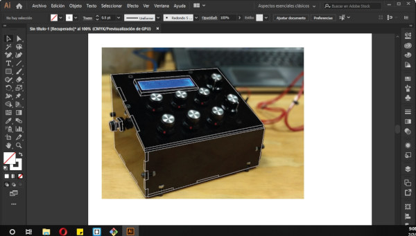
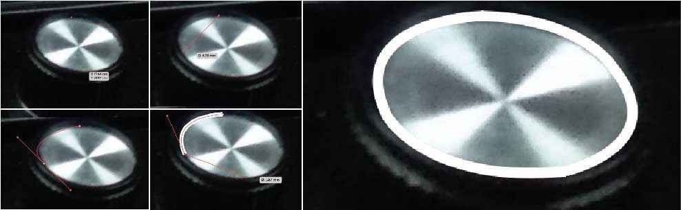
First I created an A4 size file. Then I imported the photograph I wanted to vectorize (Ctrl+Shift+P). It’s important that you unselect the Link option to embed the artowrk in the document, so if you move or delete your original file, the same image in AI won’t dissapear too. Then I created a new layer and locked the image layer. I used the Pen tool (‘P’ key) and begin drawing. This image can be useful when your learning the basic tools. The most difficult thing about doing this drawing in AI was to control the handles for the curves. Here are a few tips on how to handle the handles (pun intended). To make a perspective circle like the one from the knobs of the photo, follow this steps:
Take in consideration that selecting 4 points in a diamond figure is the easiest way to achieve the curved form.
- Select one point from the curve.
- Select another point on the curve and, without releasing the mouse button, drag the mouse until you find the right curve.
- After releasing the mouse button, you’ll see that the next segment is already curved, as AI suggests this form based in the curve you’ve done. Usually I don’t use this curve as it doesn’t always follow the pattern you want. If that’s the case for you, just click the last point you’ve drawn to delete this curve suggestion.
- Repeat the same steps for the rest of the curve.
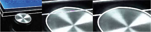
The straight lines are pretty forward to make, so it’s not a big deal. Another thing I found a little bit troubeling when I started drawing, was to delete a segment of a line. Here are a few tips on how to do this the easy way:
- Select the Pen with the option of “Add anchor point” (‘+’ key).
- Add an anchor point close to the intersection where you want to delete the segment. Make sure the seleccted line is the one you want to delete.
- Add another anchor point on the other side, again close to the intersection where you want to delete the segment.
- Add another anchor point, this time in the middle of the segment.
- Press ‘A’ and select the last anchor point and delete it. It should delete only the selected segment.
- If you need to, adjust the remaining lines by double-clicking the edge points of the lines.
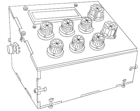
At the end I have this, the drawing of P_A+L! to soon become a sticker! I’m pretty excited about this.
Tip: ALWAYS SAVE YOUR DESIGNS!
I think this is prety obvious for any software, but I found (the worst way) that AI closes all the time. On the other hand, everytime it opened again, it automatically saved a copy of the file, so that’s pretty good, but it’s better to don’t take the risk of losing something important.
Inkscape
I want to use more open-source softwares. I have used Inkscape to vectorize images to then lasercut. But I have never designed anything there. So I’ll follow a similar process than Illustrator, to make a sticker out of an image. In this case, I’ll be drawing the Armadillo, an interactive parametric installation designed by students of DAFD and fabricated in Fab Lab Yucatán. This image is simpler than the one I made in AI.
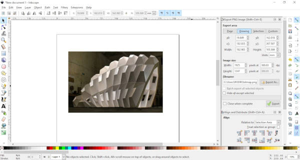
For this I used the Bezier tool (Shift + F6). It’s pretty much exactly the same as the Pen tool of AI. I actually find it easier and faster to use because you can end one line and draw another with less commands or clicks. The making of curves is pretty much the same, although I didn’t use it in this design.
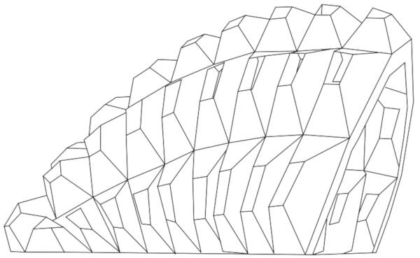
This is my second sticker design! Pretty simple but I really like it.
GIMP
For compressing images I’ve been using Gimp, that is like an open-source version of Photoshop (PS), or that’s what I have seen.
This is a simple guide for compressing images, you can experiment with the values, but this is my standard set up for this documentation:
- Open Image (Ctrl+O).
- Image > Scale Image.
- Width: 600. Height will change according to width if you have them chained together, which I recommend.
- X and Y resolution: 72… although It seems that this doesn’t matter if you’re only using the image on the web and not printing it, so you can stay with 300. I actually exported both of them and proved that they have the same file size, which is really important.
- Export As… (Ctrl+Shift+E)
- Quality: 70. Click the “Show preview in image window” to see how it changes the image quality.
- Export.
Sometimes I like to group a couple of images into a single one. For that I found that using AI is easier and faster. First import the images into AI (Ctrl+Shift+P), rearrange them, select them all, right-click > export selection, select JPG 20 format and export.
Update: Right now I’m testing Bimp, and extension that let’s you apply GIMP manipulations to groups of images.
3D
Autodesk Fusion 360
Fusion 360 is a cloud-based modelling software. The nice thing about this software is that it has an students version to download for free. It has great integration with Eagle, a software for designing electronic Boards. With this integration you can export your electronic design into Fusion 360 and work into a case or a 3D model of your design.
I have used Fusion 360 since 2017 when I was studying Mechatronics Engineering. I switched to it from SolidWorks, and fell in love with it. Is easier to use and very powerful. I have used the designs to 3D print, lasercut and manufacturing with CNC router.
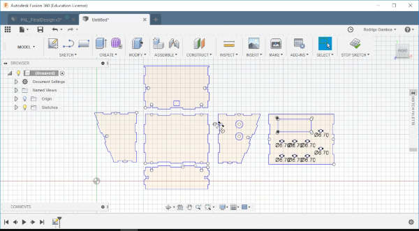
What I want to do with Fusion 360 this time is to make the 3D model of P_A+L! I already have the 2D design that I used to lasercut the pieces a year ago to fabricate the console. So I’ll export this into Fusion 360 and extrude it.
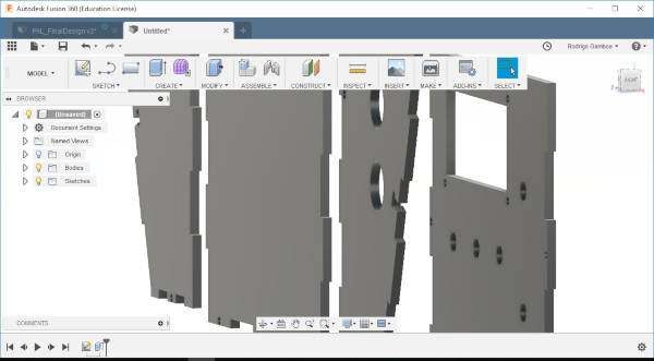
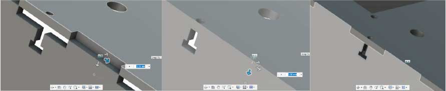
So now the extruded lines are Bodies. You can see them in the left menu. To Join componentes you need to first convert Bodies into Components, so you go to ASSEMBLE>New Component, or you simply click the New Component Icon (the three cubes with a sum symbol). You select the option From Bodies and then select the pieces, you can select many by pressing Ctrl, or by dragging the mouse and selecting the area. You hit OK. On the left menu you should now see the new created Components. Now you can use the function Joint by pressing the ‘J’ key or clicking the Joint j. Joining components could be a little bit tricky at first, so let’s take this example. I need to join these two pieces perpendicularly. So I’ll click an specific part of one of the pieces (the one that you want to move) and then click where it will join in the other piece. As I want this piece to move in a 90 degree angle, I’m gonna click the edge of the top side. Note that a little circle will appear to show the different options. Now you can select the edge of the other piece. The pieces will now join and it will appear an option to move to pieces in any direction if thee assembly didn’t match as you wanted to. I did the same process for every piece.

On the last piece, I encountered with the example I mentioned before, where the pieces don’t assembly exactly. For this I used the guide arrows to move the piece until it assembles correctly. I moved it 3mm. It’s usually an integer number.
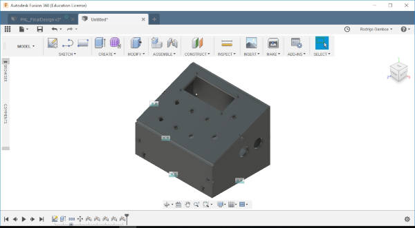
There I have it, the first version of my console P_A+L! on 3D!
Tip: If you don’t like to see the dimensions of your sketch all the tim, as me, you can right-click the sketch and unselect Show Dimension.
Sketchfab
Now I want to import this model into my Fab Academy webpage documentation. To do this I need to upload my model to Sketchfab. After signing in, I see the required formats for the models and compare them with the export types from Fusion 360. It seems that I can only use .igs, .iges. That format worked great for me, but if you want to export to STL from Fusion 360, you can follow this useful guide. I had to do some tweaking to my original design in Fusion 360, like moving it some units so it appears centered in Sketchfab, but not a big deal, Sketchfab let’s you configurate a lot of things from their website, like materials, lighting, background image, move and rotate the axises, and what I found most useful, replace the model, so if you make a change in your original model, you don’t have to delete and upload again in Sketchfab, just hit the replace button and that’s it.