4. Computer controlled cutting
This week I worked on exporting parametric designs and cutting them out of various materials.
Producing the design
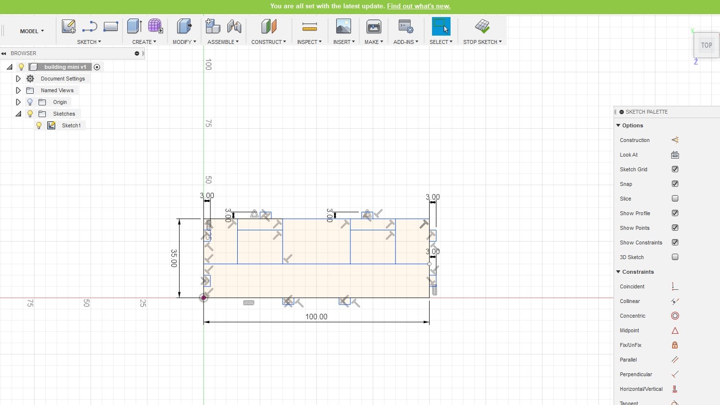
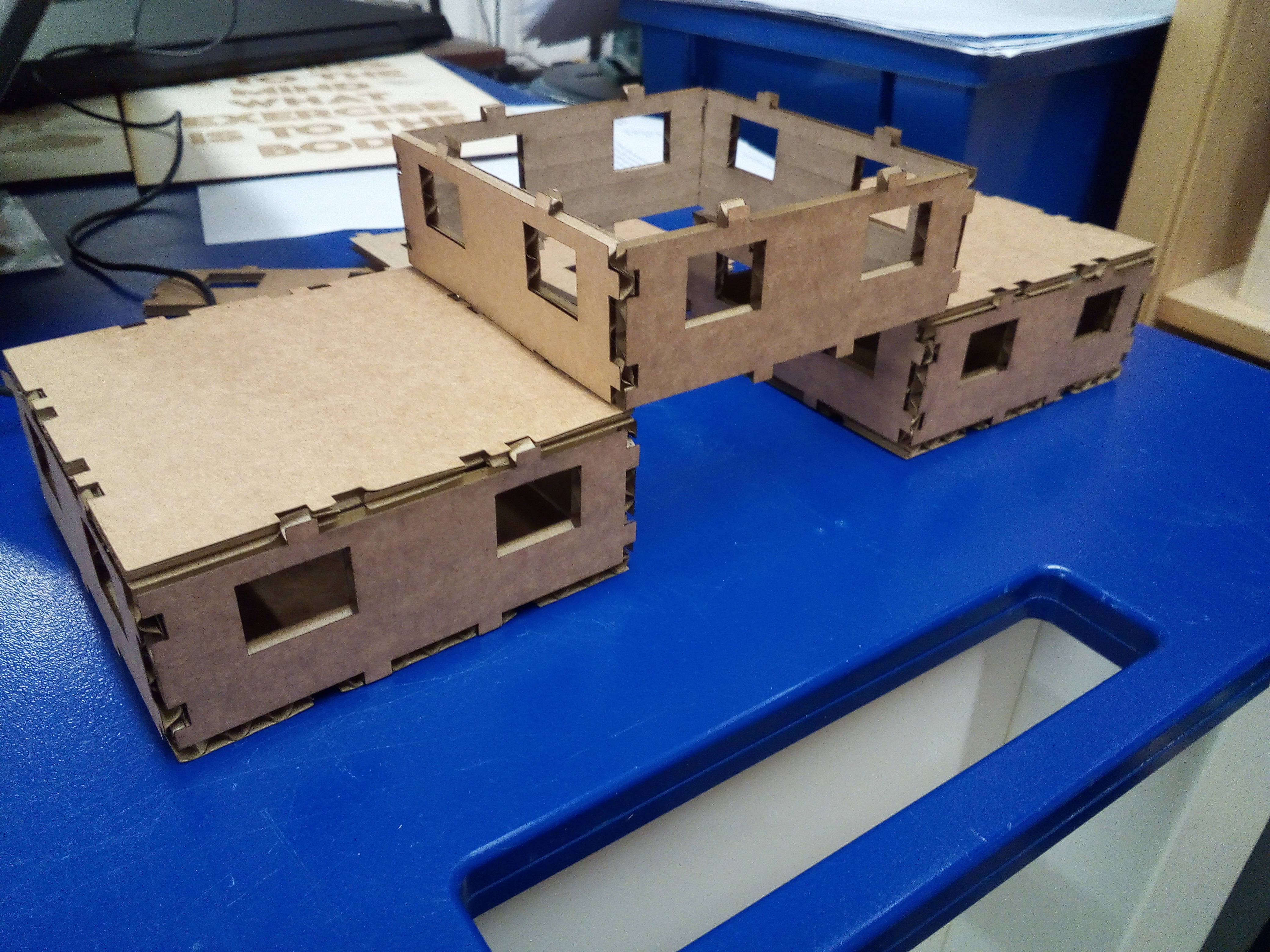
I started by deciding that I wanted to make a small piece of scenery. I enjoy modelling in my spare time, be it building dioramas or general war gamming, so I thought this would be a good chance to produce something I am interested in as a hobby. So, I set out to produce a small modular house: My aim was to produce a small set of simple pieces that could be used to construct basic buildings in a modular fashion which could then be used as scenery for a variety of purposes. I started with two simple designs: a base/roof and a wall with windows. I produced both of them on fusion as sketches as it is software that I am comfortable on and one that allows me to input the specific parameters needed.
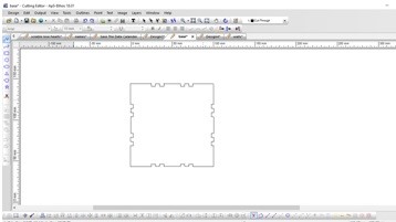
First I did the part that would serve as the walls for the structure. I designed it to be cut in 3mm material, meaning that the part is able to snap fit both in line and at 90 degree angle from the same part, allowing for ease of customization when designing the building.
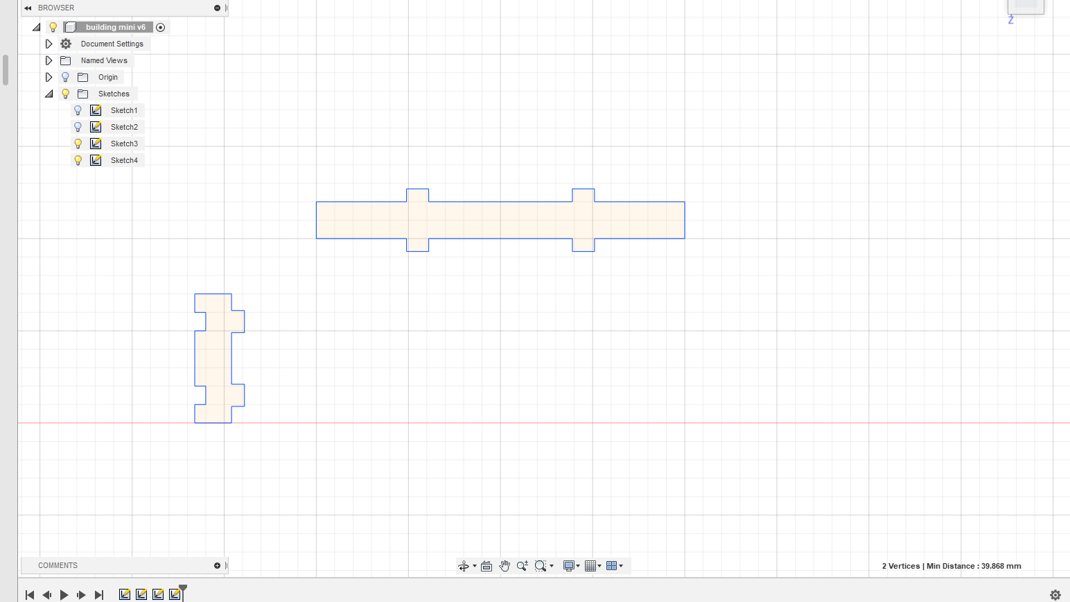
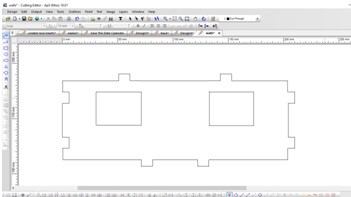
Then I did the part that would serve as both the roof and base of the model, once again following the same parameters. I designed it with two different sets of snap fitting holes, one for the wall above, and one for the wall below, this way the same floor can fit both parts above it as well as underneath simultaneously.
Once I had both parts done I did another further two connectors, these would serve to anchor the buildings sidewise so that there is no limit to the variety of configurations.
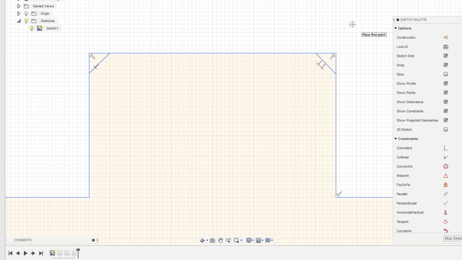
After the designs where done, I went back to the designs in order to add the small indentations needed for a snap fit kit. These indentations serve to better slide one part into the next: the key issue when designing a press fit kit is achieving the correct tolerance. Too little and the part will not fit comfortably, too much and the part will just slide off. A solution to this issue is adding an indentation to the side of the teeth. This serves to guide the teeth into their grooves, meaning that one can be far more lenient with adding very little tolerance and still have the piece slide effortlessly.
I added these indentations to all of the teeth across all of the designs.
Because of the indentations I did not thing it was necessary to put any form of tolerance, as the kerf on cardboard is often quite aggressive. Laser Kerf refers to the amount of material removed by the laser when doing one pass: Whilst the laser can be incredibly thin, it is incredibly hot, as such has a tendency to burn at the edges of the material. How much is removed depends on the material, on materials such as acrylic it can be quite negligible, but on cardboard it has a tendency to be quite aggressive.
Because of this, I figure that it would not be necessary to add any extra tolerance.
Cutting the design
Once the schematics where done, it was time to produce the parts.
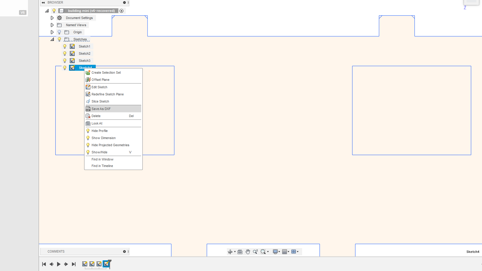
I exported the design from Fusion to DXF. DXF is usually considered to be gold standard when it comes to making files in used to make parts. The software can also interpret other file types such as PDF, but DXF is always a safe bet for any form of cutting.
Once I had my file I placed it into a USB and then loaded into the ApS-Ethos software the laser cutter uses. ApS-Ethos is software exclusive to the laser cutter. Whilst it is possible to make certain changes to the design, this is very limited. So it’s best to make sure our design looks exactly the way we want it before putting into the software.
Since this was a case of simple straight cuts on cardboard, I simply set the cutter to its default cutting parameters at three passes. The exact parameters used to cut materials will vary wildly depending based on the type of machine used, the type of gantry it operates, the power output, etc. In our case, the software already comes loaded with the base settings for cardboard of different thicknesses, so I did not have to make any edits to the settings.
With the right settings selected, I then had to tell the software which lines to cut in what way. The machine colour codes the lines depending on if you wish to cut, raster, engrave etc. However in this case I am only cutting and as such every line was set to Cut-Through Black.
Once everything is in order, it’s just a question of double checking dimensions and parameters to ensure everything looks good. Having done that, we can proceed to send the various designs through the laser. From this point on, it was just a question of pressing play on the various parts, waiting for the cutter to finish its job, and the sending the next batch through, until I had various pieces stocked and ready for assembly
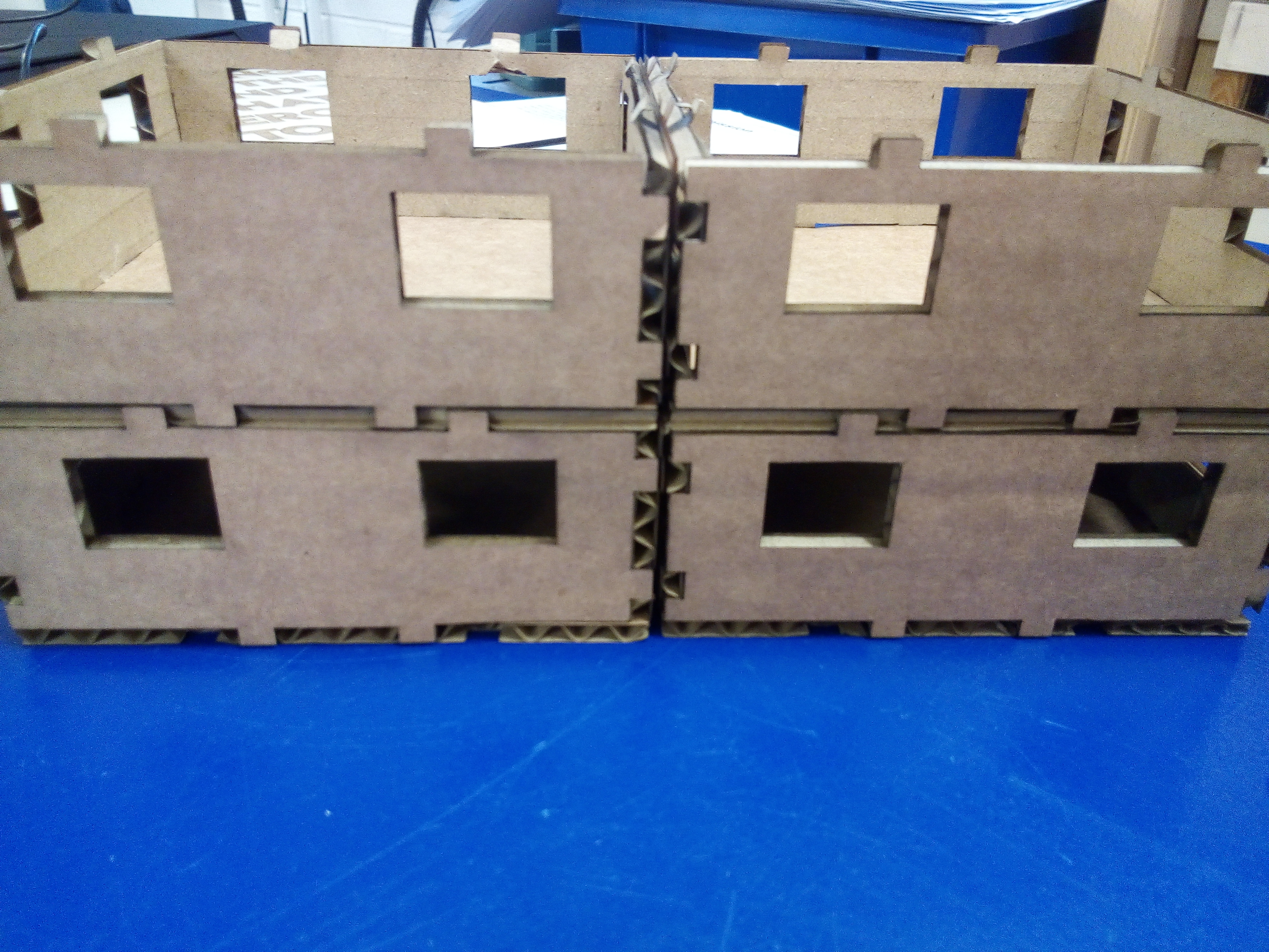
Results
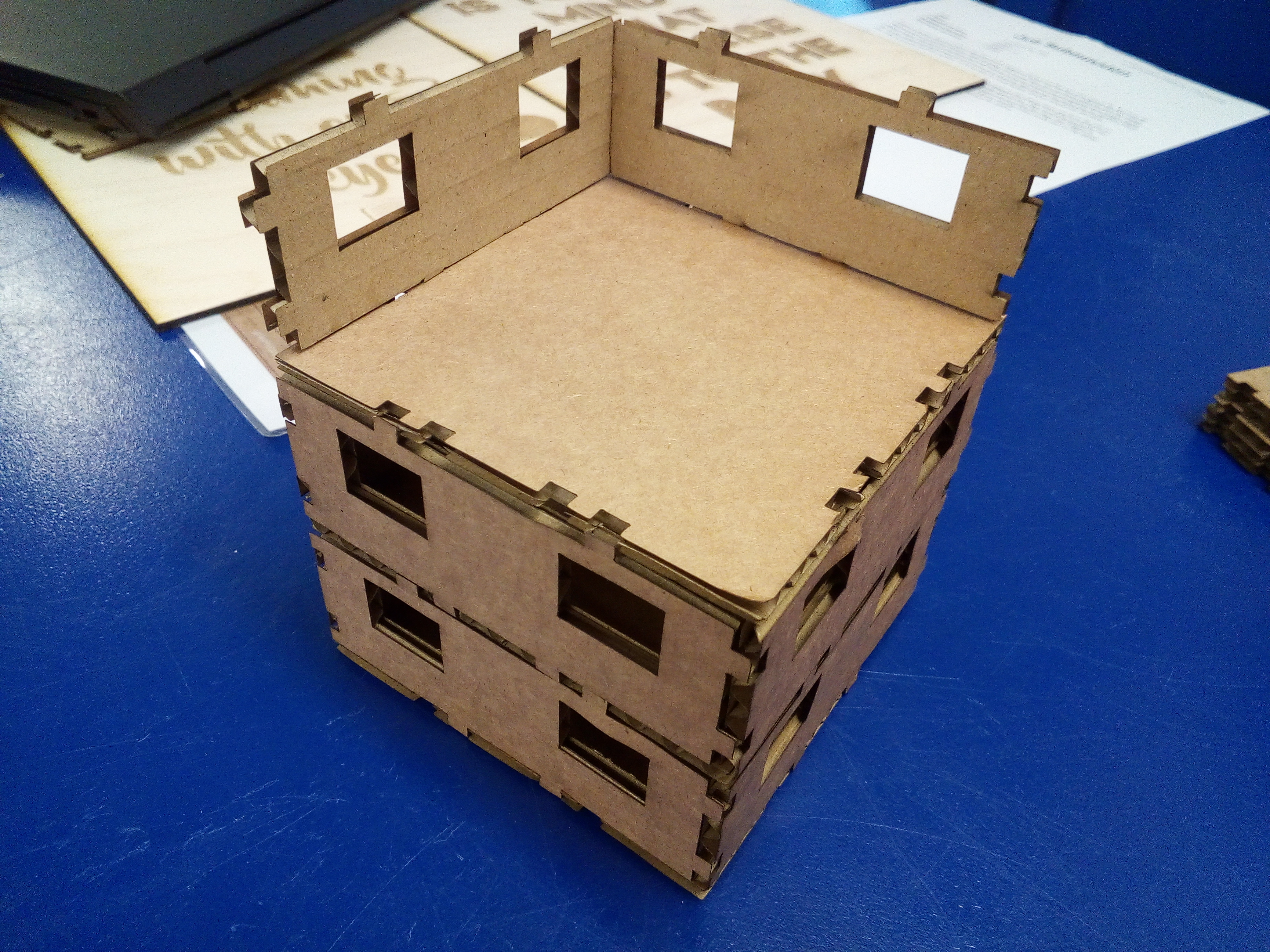
The pieces came out rather well; I ended up not actually needing the connectors as much as I thought I was going to. Not adding any extra tolerance proved to be a wise decision as the parts fit snugly just with the kerf. If anything, perhaps the cardboard was a bit too loose: Not enough for it to fall off, but a little bit more than I would have liked. If I re do this process in the future then I will ensure to add avery minor amount extra thickness to the part.
Vying cutting
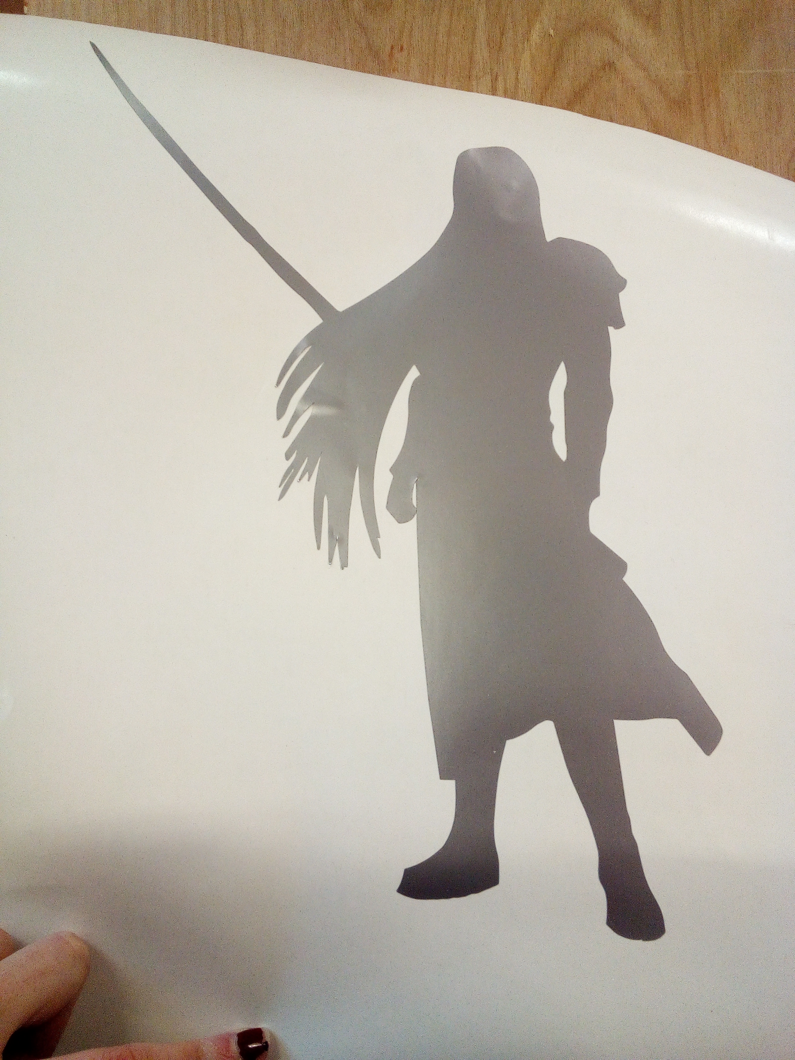
The next step for this week’s assignment was to cut out a shape using the vinyl cutter. I decided that I was going to cut out a silhouette of Sephiroth.
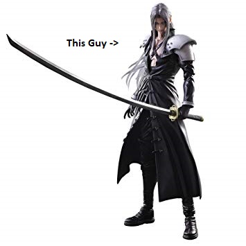
Sephiroth is an incredibly popular character a Japanese Fantasy videogame franchise called Final Fantasy. The character has become a huge element of popular culture, and can be seen in a large variety of mediums. I thought it would be very cool to cut out a large Sephiroth-shaped sticker to put on a computer, and so I set out to create the sticker.
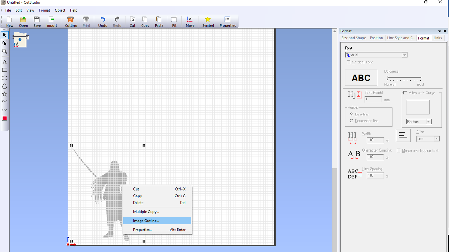
I started by creating a quick sketch of the Sephiroth silhouette using Illustrator, and then exporting it. I opened the file in Cut Studio, the default software of the Roland Vinyl cutter.
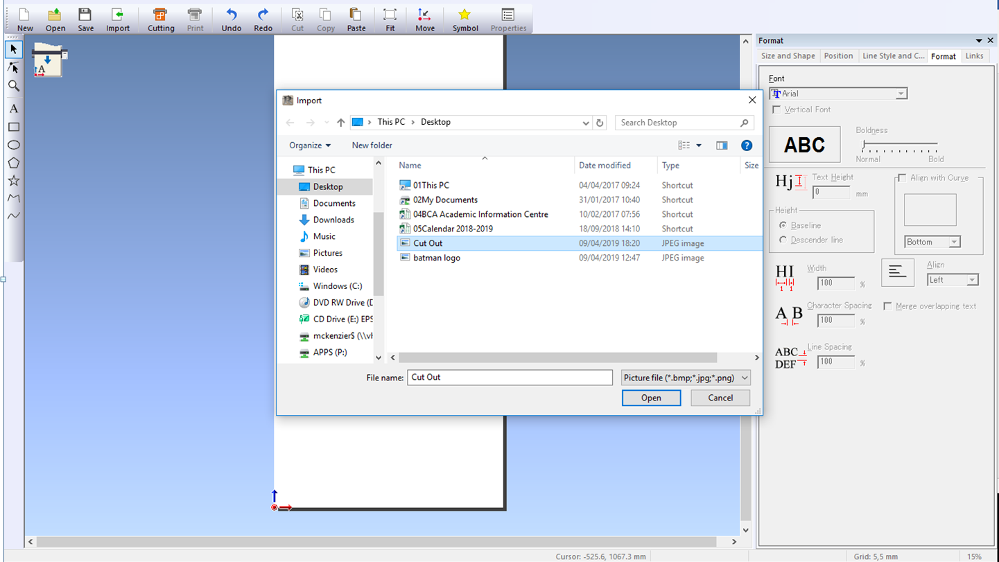
Once the picture was in the software it was necessary to trace out the outline, so that the software knew where to cut. Thankfully cut studio is quite good and discerning the outer perimeter of solid shapes, and thus was able to calculate it on its own.
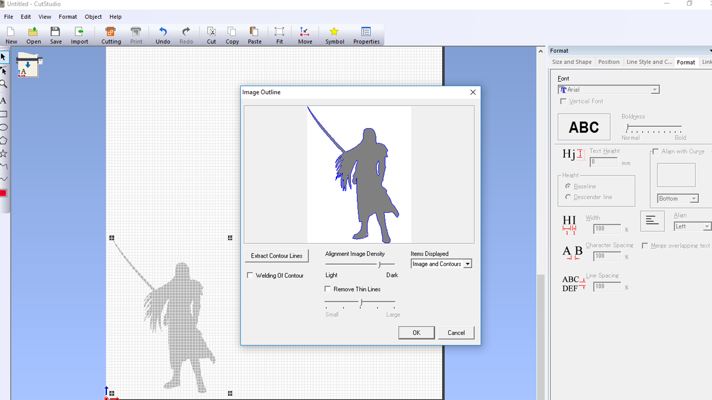
Having the outline done, I deleted the original image and placed the outline on one side. Then I checked that the outline was placed in the correct side of the roll and more importantly, that it was the correct size.
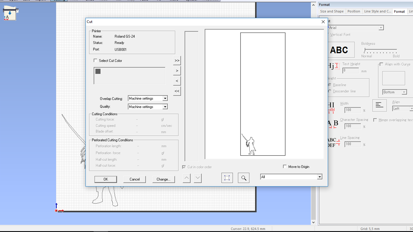
Once I had double checked that everything was correct on the software I loaded the material into the Roland. In this case, silver sticker. Once everything was ready I sent the file through. I was a bit worried about the design not coming out looking well, especially the sword as it is the thinnest part of the cut. However the Roland behaved itself admirably and managed to cut the first time round without any issues.
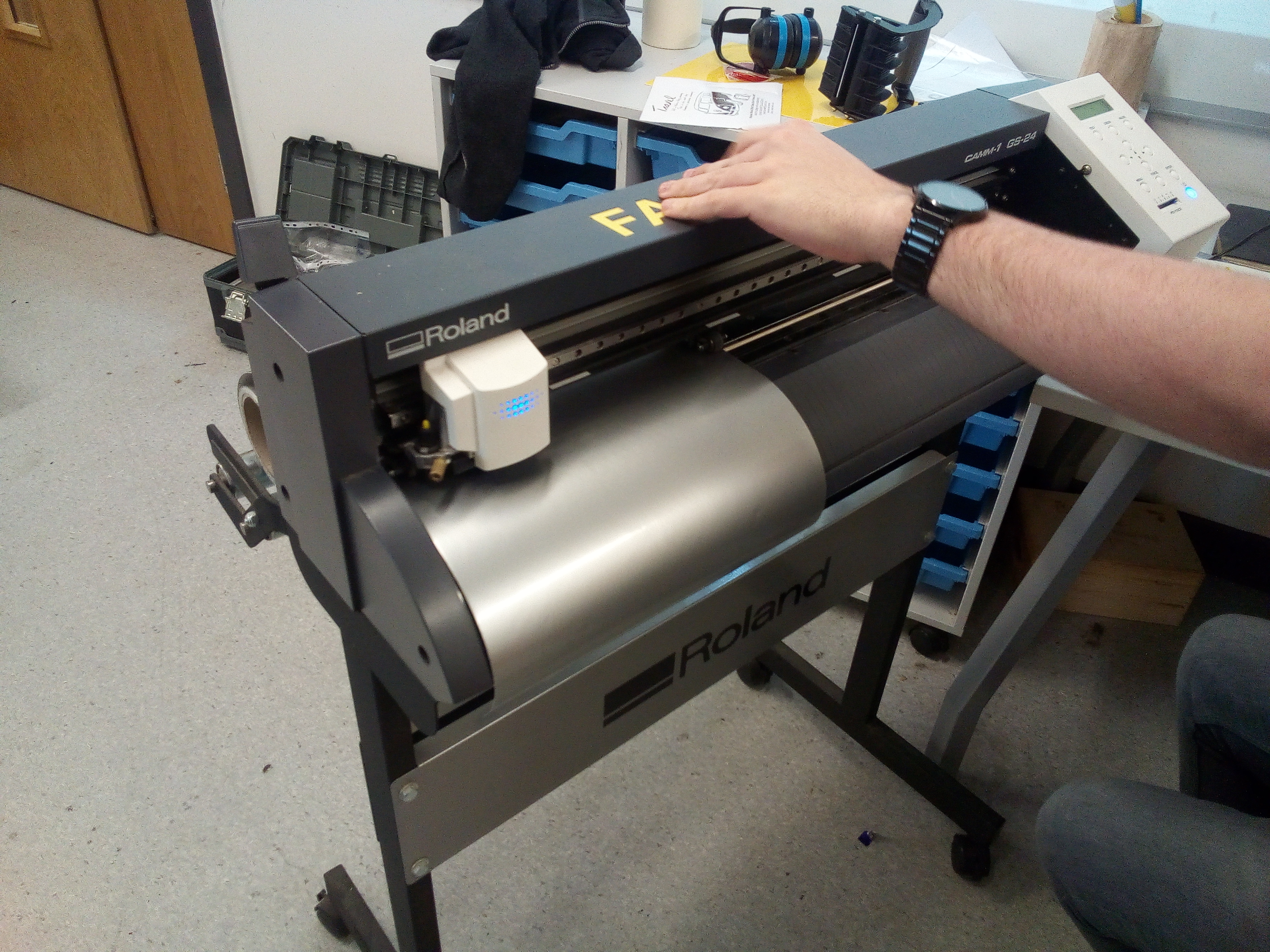
And thus, I had my very own Sephiroth sticker.