Computer Controlled Cutting (week 04)
Group Assignment: (characterize your laser cutter’s focus, power, speed, rate, kerf, and joint clearance)
Refer to Annie Ferlatte group assignment section for details
Individual Assignment (cut something on the vinyl cutter design, laser cut, and document a parametric press-fit construction kit, accounting for the laser cutter kerf, which can be assembled in multiple ways)
Part of my work as a teacher in the context of my fab lab, stands to initiate curiosity, interest and imagination among my students. I also manage a small school enterprise, called Fabinnove, offering conception and realization to the school board community and city one's. In doing so, we often create materials for our FAbLab portfolio use to promote our capabilities and attract customers.
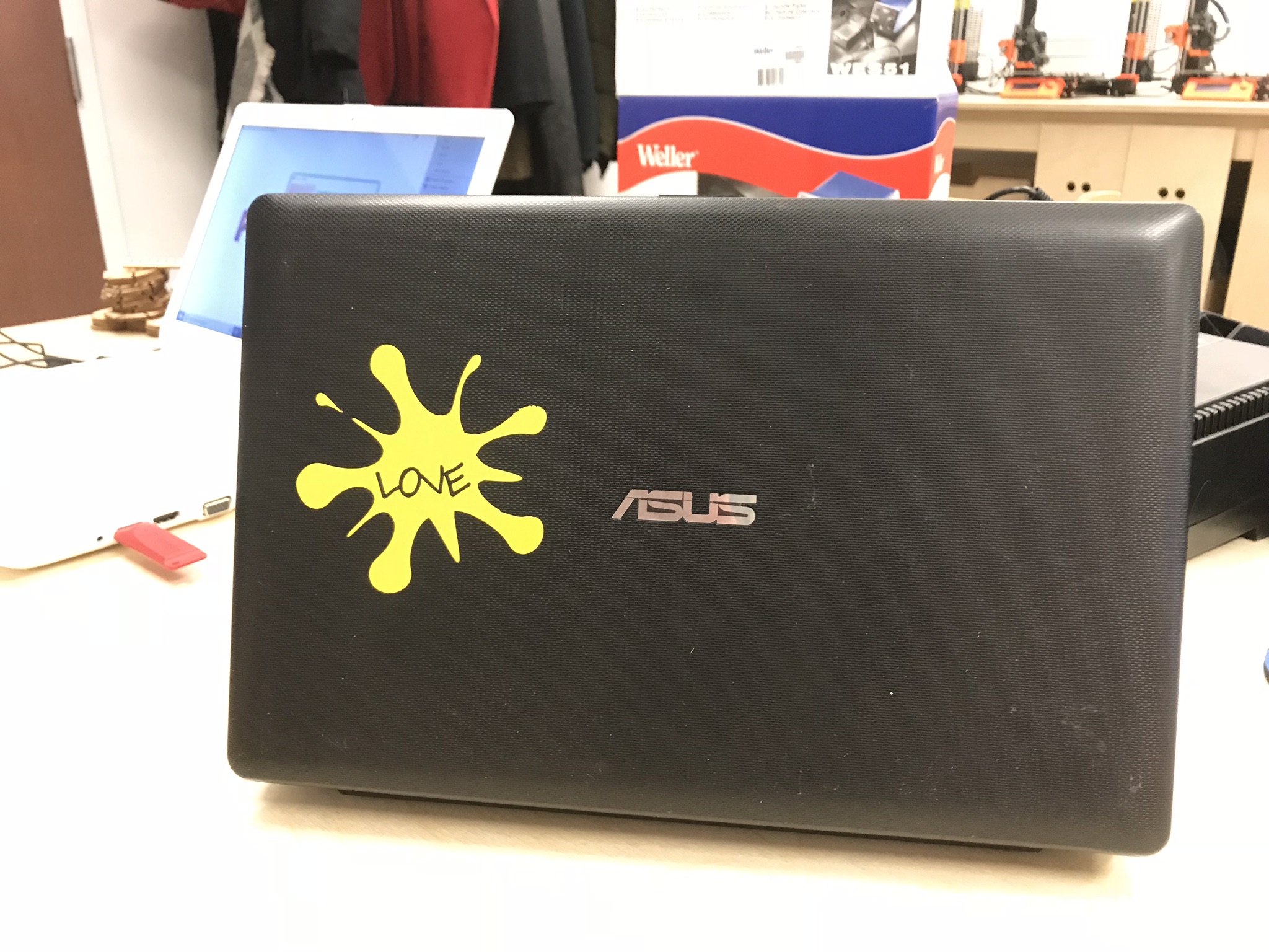
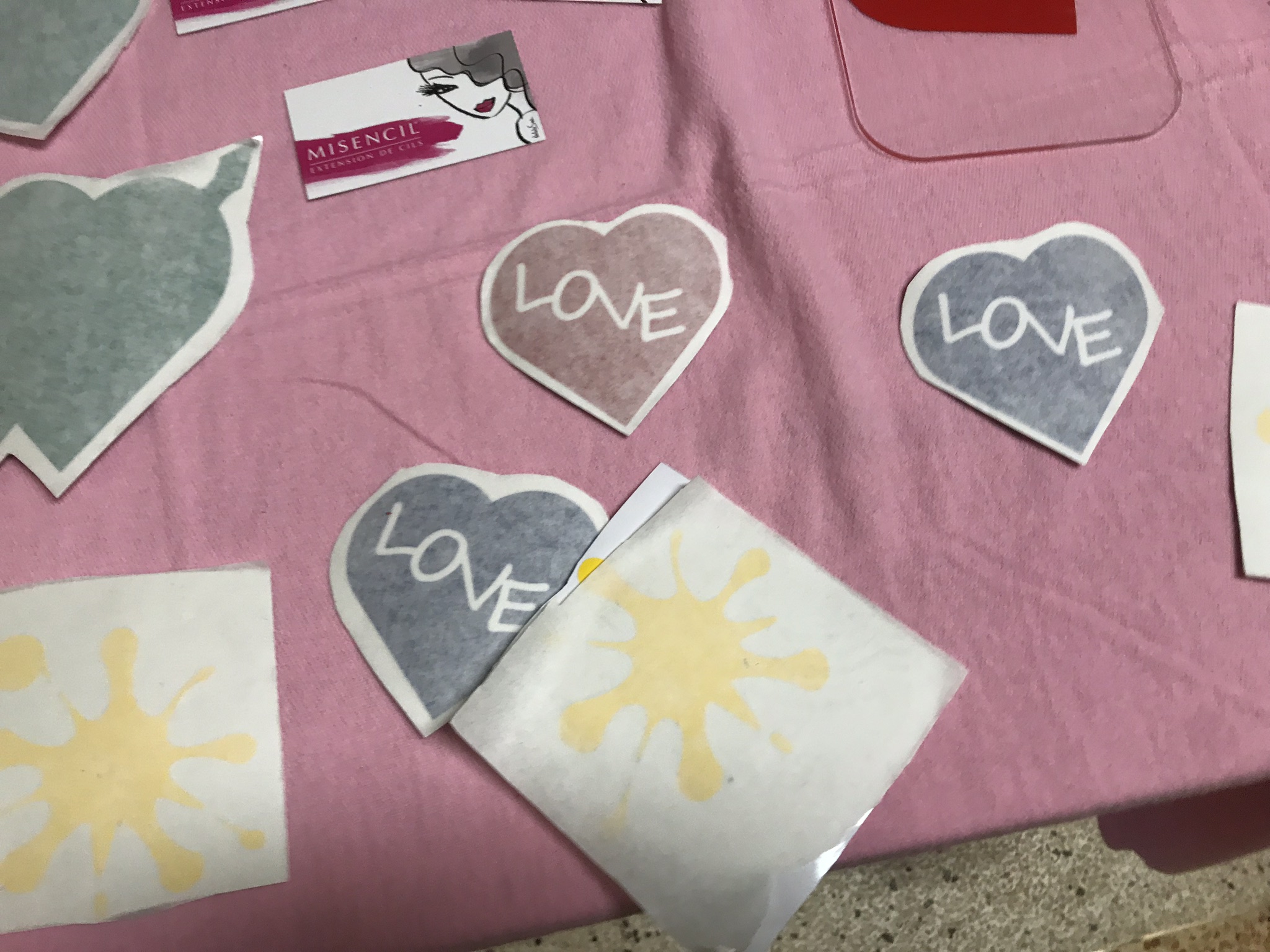
Recently, we held a booth show during lunch time at the Center, holding demonstration of our 3D printing, vinyl and laser cutting capacities. To do so, given this week assignment, I created a series of 2D images using Inkscape. I am not going to cover in detail all the necessary step involved here, suffice to say, the splash patterns were done using a circle and then modify the perimeter using tools like Bezier curves, stretching and curving. Here's examples of some of the shapes created (and yes it was St-Valentine weeks!!):


The
construction kit
For this task, I used fusion 360.
Before I design the “puzzle” I needed to generate a cuts template
to ascertain the proper settings to account with the material to be used here
the Kerf. Again, in Fusion 360 a parametric template was generated, laser cut
and used as a guidance.
Find here after Inkscape screenshots
of the process:

A series of increasing width
kerf were drawn and place next to a rectangle, the increasing width
“slots” (here in pink) are to be subtracted from the rectangle
creating a comb ounce the slots are subtracted from the holding material. Then
adding labels for each varying slot, creates the tool to be used for the
“construction kits”


Find hereafter the final product to
be used into the designing of the “construction kit”:
For the
construction kits itself, I worked into Fusion 360 creating different shapes
and placing symmetrically slots. The intent behind this was to generate shapes
to be united “randomly” as one would be inspired to
“play” and let their imagination free.
Find here some screenshots of the
Fusion process leading to the creation of the shapes:
First the basic 2D shape and slots
are created and lay in “symmetrical” position and into a
“parametric” design:


Then while in sketch mode the slots
are subtracted from the main shape:

Further process implies extruding the
resulting piece to create the 3D model:

When shape design is satisfactory, a
drawing of the resulting piece is generated and further processed to laser
cutting using Inkscape by exporting the part into PDF format:

Several shapes were generated through
this process and ultimately cut into a single 1/8-inch plywood sheet:

The final sheet after the cuts is
shown here and one iteration assembly as well:

Altogether,
I’m satisfy with these results. There’s still room for improvement:
1-
Kerf
values used here, could have been wider, parts are not always sliding well. I
retained a value of ______ and could have used bigger creating a easier sliding.
2-
The
opening ends of all the sluts designed here are straight. Clearly these should
have been smoothed with an angle, this would have help
quite a lot assembling them.
Overall, the
prototype is functional, find here one of many assemblies made possible,
variants are possible, only limited by number of pieces and retained angles of
the sluts on each part against the center of the piece.

