Assignment Four: Cutting with the vinyl and laser cutters
This week, the challenge is to do three things:Use the vinyl cutter
Test the laser cutter
Build a laser cut assembly kit
Use the vinyl cutter
To try out cuts on the vinyl cutter, I am going to make a sticker that has Montreal and its metro line on it. This is my first time living in this city and I think the metro is pretty wonderful compared to my last city (Ottawa) which had none.I found two good pictures of Montreal and the metro line running through it, but because I had never used a vinyl cutter in echofab before I decided to try to print both individually first before joining both.
These are the pictures I found: a picture of Montreal from a sticker and an image of the subway lines.
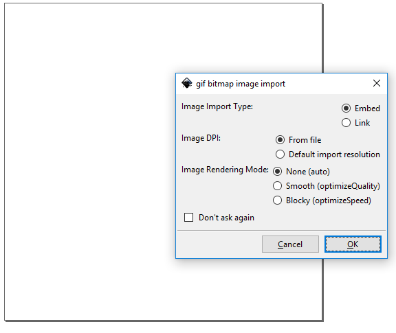
I opened a new file in Inkscape and used Ctrl + Shift + D to resize the sheet to a square. Then I brought in the map image.
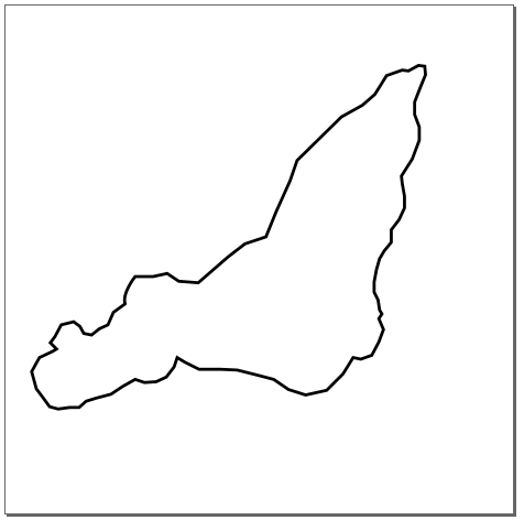
Next, I created a layer on top of the image and traced out the city's boundary using the bezier tool.
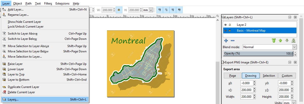
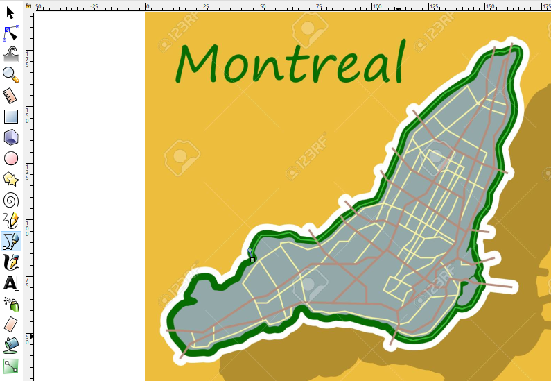
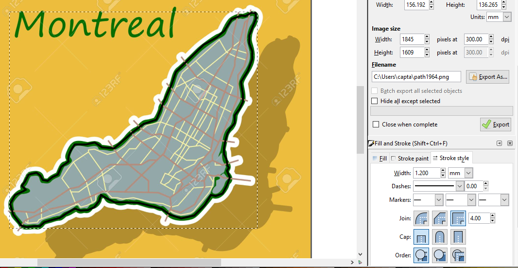
On completion, I increased the width of the boundary line to make it a better cut, 1.2mm the width dimension using the fill and stroke tool.
After this, I hid the first layer with the image and I had the boundary done!
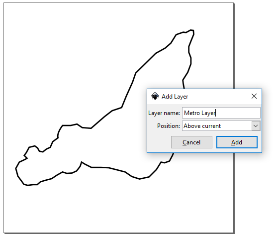
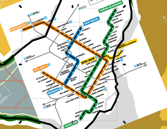
On top of the first layer, but under the trace layer, I added a new layer. In this layer, I imported the map of Montreal's metro system and resized it to fit the curve of the trace and the earlier map as shown below. Once this was done, I traced out the metro lines.
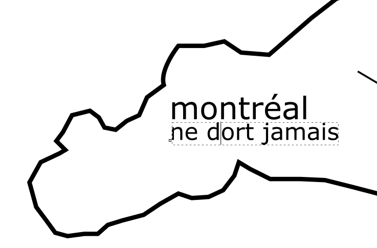
Taking off both image layers, I had the finished trace. Then, I added a caption 'Montreal Never Sleeps' or 'Montreal Ne Dort Jamais' in French.
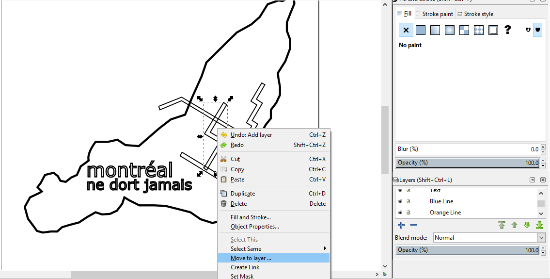
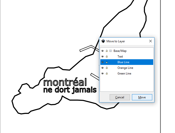
Next, I moved the design to a new sheet and set into layers so that I could print one after the other with the different colours.
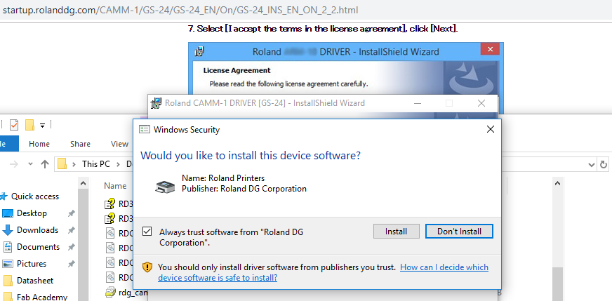
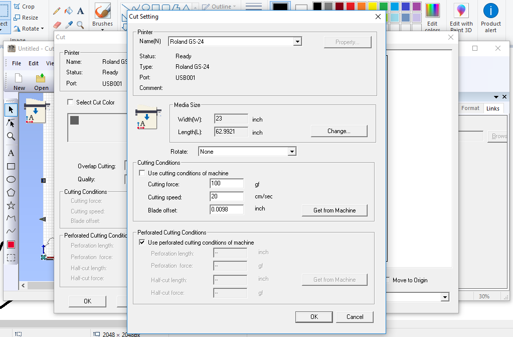
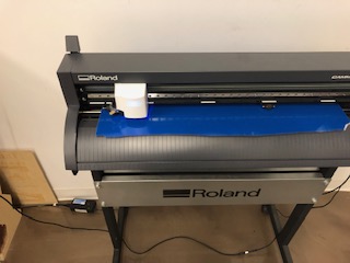
In order to use the Vinyl cutter, I had to install it first using the steps described in the User Manual. The machine in the lab is a Roland CAMM-1 GS-24 model. The steps listed require four installations, culminating in Cut Studio which requires a plug-in for Inkscape.
After installing and setup, one can open Cut Studio by running the Inkscape extension.
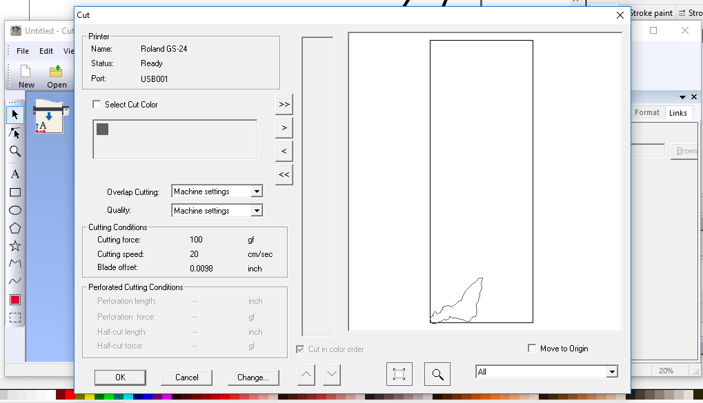
Thankfully, Cut Studio shows a render of your design before it cuts it. Shown below is the render of the map image layer the design.
Once this was ready, I set the vinyl cutter at the origin guided by the marks on the printer. I set the speed of 110 gf and 20 cm/s in Cut Studio.
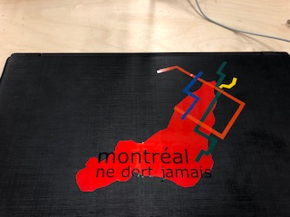
On clicking OK, the file is sent to the vinyl cutter and printed. The final result is below and the file is saved here.
Test the laser cutter
The next task is to use the laser cutter, first trying out test cuts to learn the cutter and then making a design to be fit together.
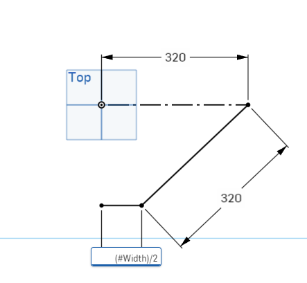
As the test cut needs to be parametric and have different sizes, I decided to use Onshape to try this out. Onshape has a great variables feature which can be used to declare different length, angles or dimensions.
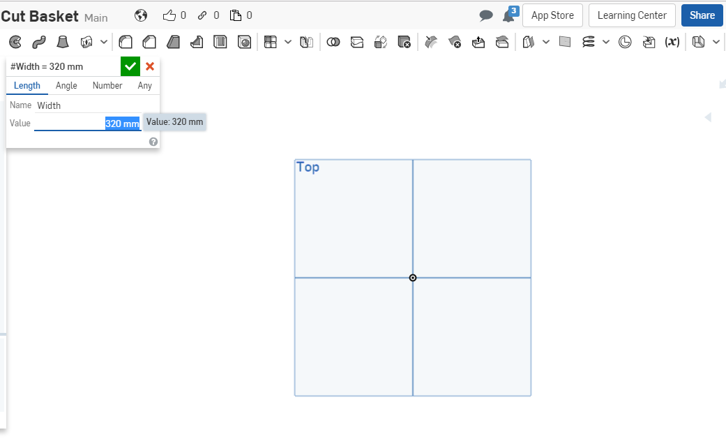
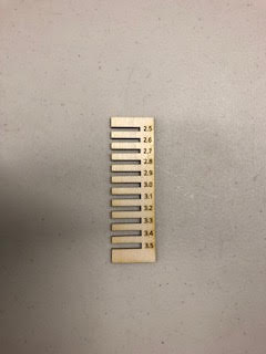
The first variable I created was for the basic size of 2.5cm, my intention is to use create each other size as an function of this first one.
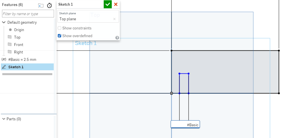
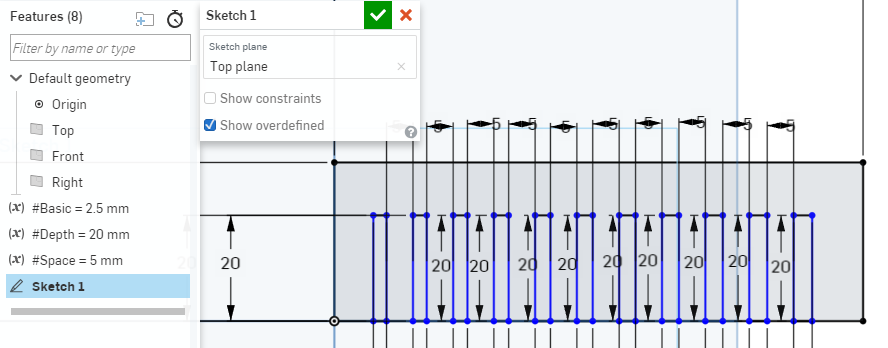
Then, I created all the remaining cut sizes using the variables Space and Depth to control the spacing between the cuts.
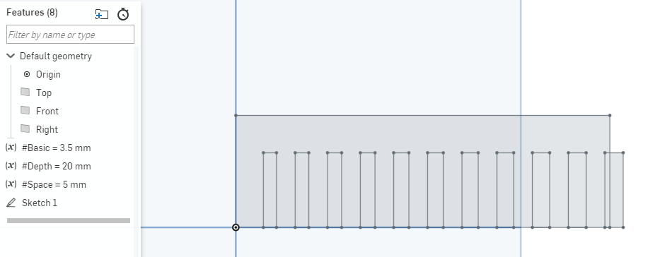
In order to check that the design was truly parametric, I changed the value of the Basic variable to see how it would affect the sketch. Below, you can see that it did as the sizes are now outside the total length.
Once sketch was done and I had added some text specifying the sizes, I then created a drawing and exported the drawing as a PDF so that I could open it with Inkscape.
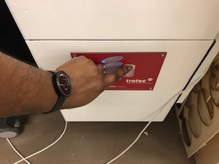
Within Inkscape, I changed the lines to red for future use of the laser cutter. To use the laser cutter, I had to install Job Control, the software used by the Trotec Speedy 300 Laser Cutter, it is a 60 Watt Carbon (IV) Oxide laser that has a job size of 29" x 17". The manual of the laser cutter I consulted is here.
When fully installed, I clicked Print within Inkscape, and chose the laser cutter as the printer. This command opens Job Control.
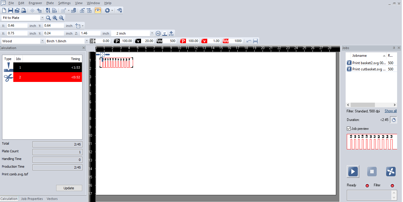
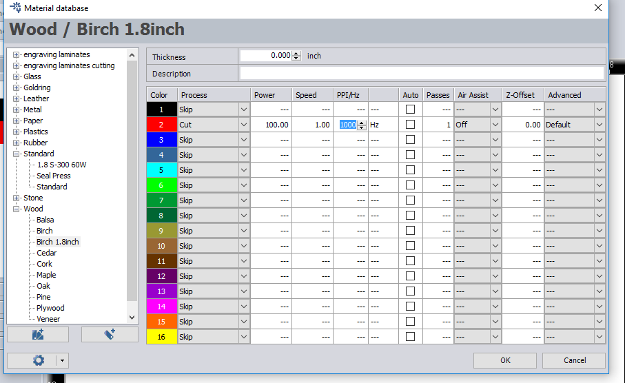
As it's the first job, I had to create new settings for the type of wood - which is Birch 1.8mm. The settings are were you set the colour for engraving and cuts, as well as the speed and frequency of the laser for both.
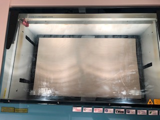
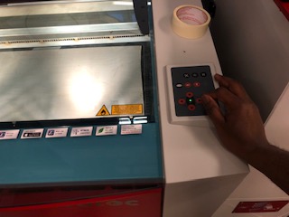
Next, I fed the laser cutter with wood and turned it on. And then I placed the laser at a good starting point after using the marker to check the best height level.
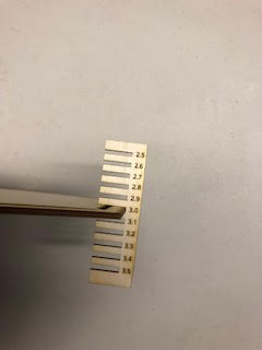
Then, I printed the design! The file can be found here. In this exercise, I learnt that the best speed for cutting the wood completely is 0.8m/min as compared to the 1.0m/m recommended.
Build a laser cut assembly kit
The final task for the week was to create an assembled kit using cuts from the laser cutter.
My idea was to have two parts that can fit to make a box, with one part holding the other on three sides. The three sides are important so that the box is guided on two degrees of freedom. The third degree of freedom is up to how close the fit is, which can be achieved by designing the holes to be the right size.
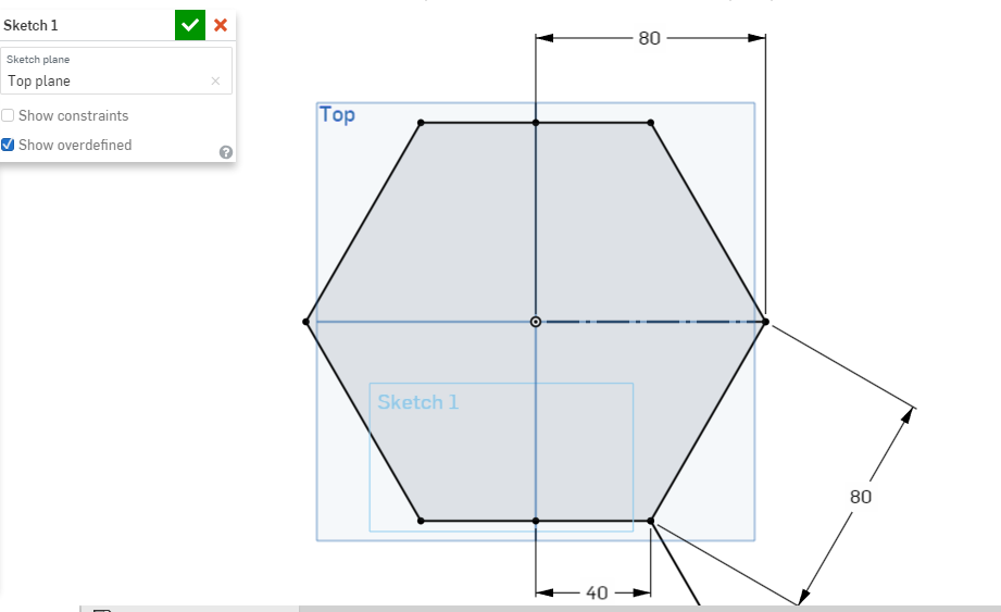
In order for the design to be parametric, using Inkscape I created a variable called Width. This will allow the size of the hexagon to be changed very easily.
Then, I created the full hexagon which forms the pattern for the first part.
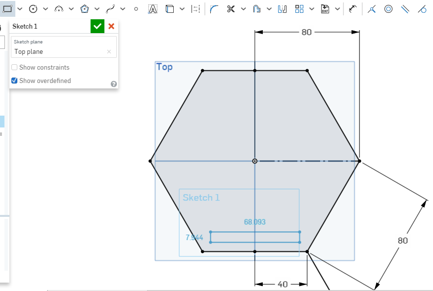
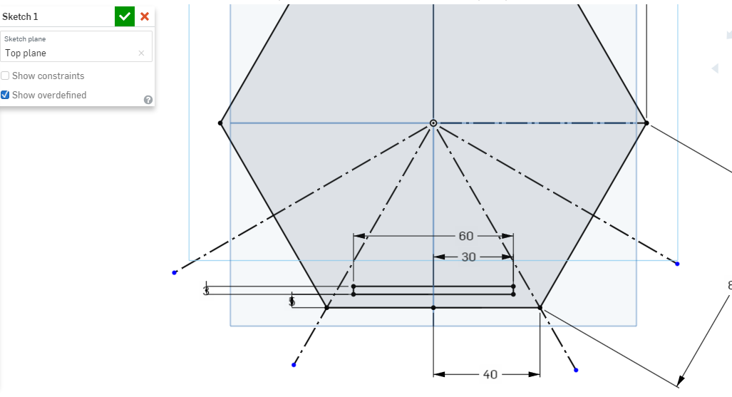
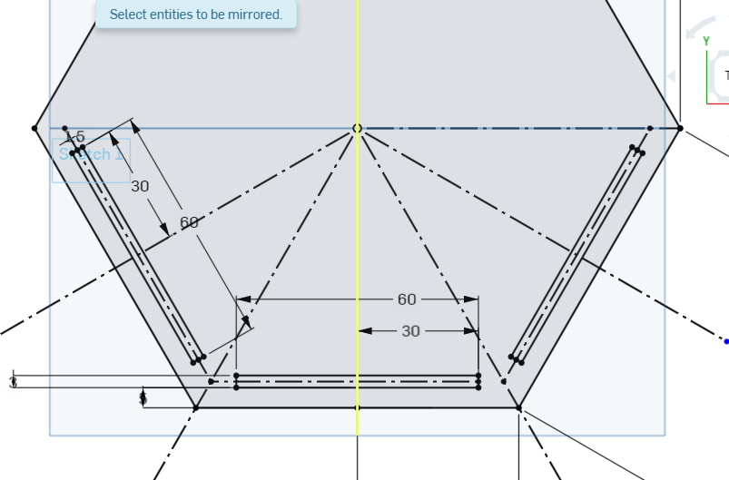
This done, I proceed to make the holes using the sketch and then mirror tools.
With this done, I extruded the sketch and created the other long part. Next, was to add both into a drawing like I did before for the test last cut and export as a PDF so it can be opened in Inkscape.
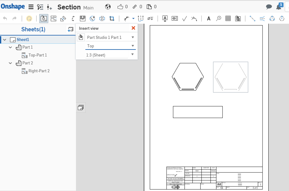
With this done, I opened the file in Inkscape, changed the colour to red and sent the design to Job Control for laser cutting.
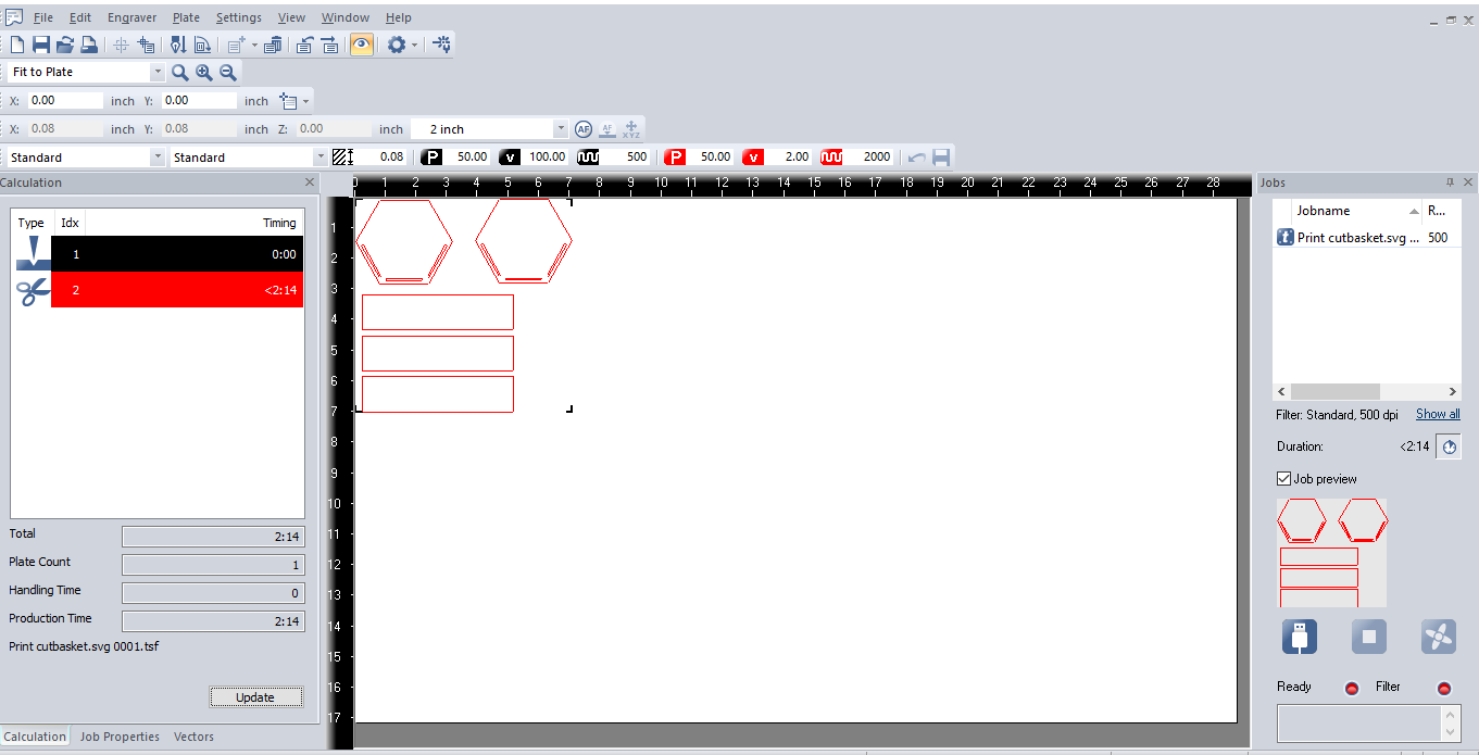
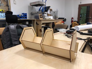
The final result came out as shown below and the files are here and here! More parts can be made to extend the box to be bigger or even to grow in more directions, the great thing about having a parametric design is by changing the variables in the CAD file it can be very easily done.