
Assignment Eleven: Input devices
This week's task is to send an input to a board we designed and read the input signal through the FTDI. My input of choice is sound, as that will be a part of my final project. The assignment in steps:Design a board with a microphone input
Assemble the board
Test the input
Design a board with a microphone input
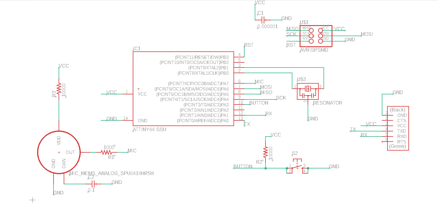
This week really kicked my ass, first I designed a board and had an issue soldering it. Francois, my instructor has shown me how to use the Polygon feature in EAGLE to make the base of the board ground. However, my board ended up having islands of grounding which did not connect to each other.After some time being in the dark, I found Darshan's project from last year. He had also worked with sound as his input and had given very good documentation. This actually inspired me to use good documentation just in case someone is stuck like me in the future and tries to use my work.
From both Neil and Darshan's board design, I saw that many designs talk about using a capacitor or amp on the OUT line of the microphone, however the microphone's datasheet showed that the part had an internal amplifier. I decided to design my board without an amp or IC (like Neil did) or a voltage regulator (like Darshan did) to see if it would still work. If it didnt, I would learn that this was to way to do it going forward.
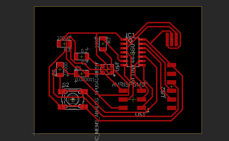
This week I learnt that by making the area of the board bigger, the autorouter can make the traces more easily. So, as long as there is enough ferrous copper boards, it makes sense to design a bigger board to get the best connections.
Assemble the board
After cutting the traces on the CNC, I got the parts together and started to assemble the components. Understanding the direction to solder the microphone was initially difficult but I checked the datasheet to know the right direction and that solved the problem. I was tense after soldering all the parts because the first board I made had issues. But my contact check showed no issues.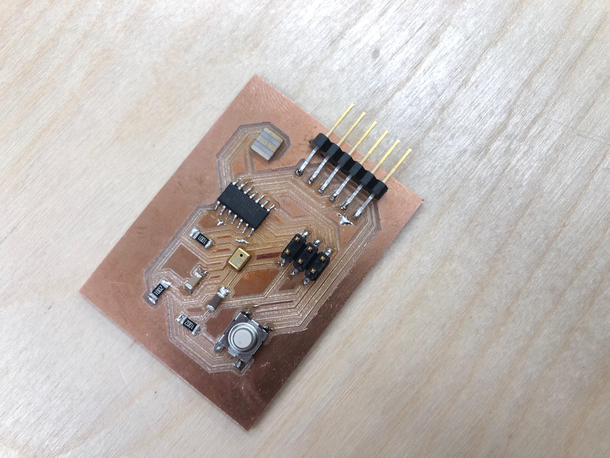
Test the input
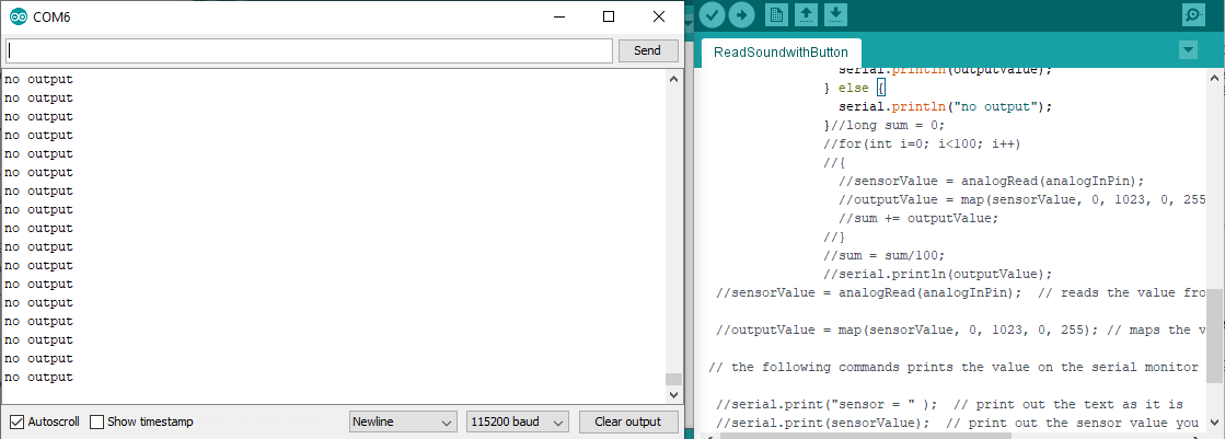
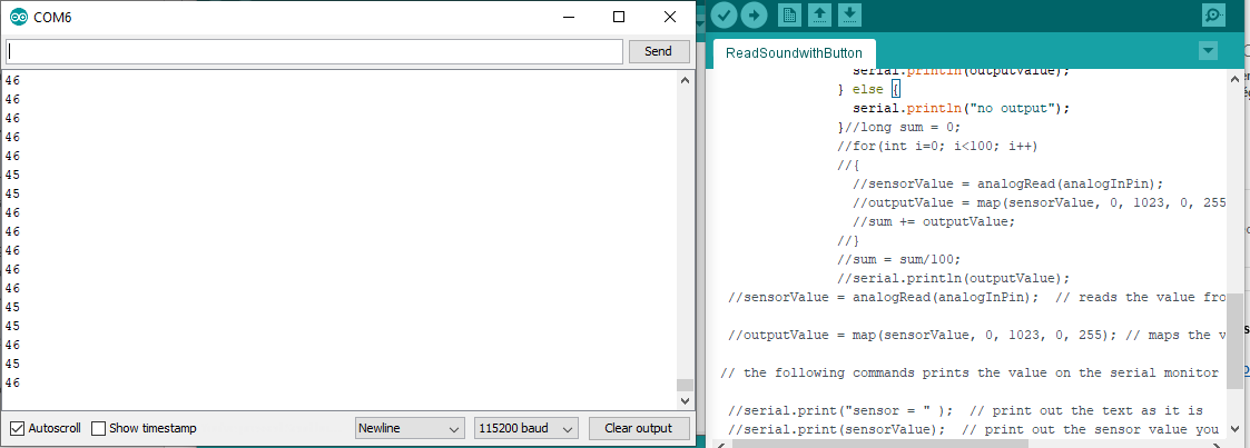
To start with, I built off the code made by Darshan. Darshan was able to detect the audio input and read it on the serial monitor. I wanted to use the button to control when the sensor could record, so that the button had to be on at any time in order to read the recording.By tweaking Darshan's code to read the button state, I was able to achieve good results to show 'no output' when there was no input and show the output when there was an input reading.
For the video below, I used the serial plotter to show how different the readings can be. The code is here
My next task will be to see if the recording can be saved to a .wav file and played on a computer.
Reflection: The output from speakers which read on a range from 0 to 1025 need to be converted to a range between 0 and 255 for change from analog to digital. This was good to learn, what I wonder now is if sound can be sent from mic to speaker without being converted to digital.