12. Output devices
This week I worked on my final project, as I plan to use sections of it for the Input, the output and the wireless week. I am using the ATTiny85 in both Transmitters and the Receiver, and took advantage of the extensive documentation around the 433 MHz Radio Transceiver Transmitter Module to build this project. Each transmitter send a specific code so the receiver is able to identify the signals received at its end.
Useful links
Gallery
Here you`ll see a picture of my Receiver design:
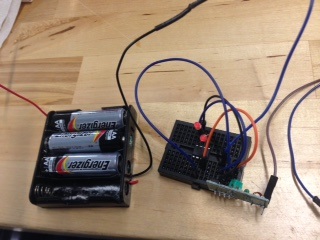
And here you`ll see a picture of my Transmitter:
![]()
Code Example
This is the code for the First Sonar Transmiter:
/*
  Board ATTiny 85
  Processor ATTiny85
  Clock at Internal 1 MHz
*/


#include <RCSwitch.h>

RCSwitch mySwitch = RCSwitch();
//Define inputs and outputs
 int trigPin = 0;    //Trig - green Jumper (0 en ATTiny)(8 en Pro Mini)
 int echoPin = 1;    //Echo - yellow Jumper (1 en ATTiny)(7 en Pro Mini)
 int duration = 0; //*
 int cm = 0; //*
 int inches = 0; //*
 int ledred = 4;

void setup() {


   pinMode(trigPin, OUTPUT);
   pinMode(echoPin, INPUT);
   pinMode(ledred, OUTPUT);

  // Transmitter is connected to Arduino Pro Mini Pin #10 (2 en ATTiny85)
   mySwitch.enableTransmit(2);

  // Optional set protocol (default is 1, will work for most outlets)
  // mySwitch.setProtocol(2);

  // Optional set pulse length.
  // mySwitch.setPulseLength(320);

  // Optional set number of transmission repetitions.
  // mySwitch.setRepeatTransmit(15);

}

void loop() {

  // The sensor is triggered by a HIGH pulse of 10 or more microseconds.
  // Give a short LOW pulse beforehand to ensure a clean HIGH pulse:
  digitalWrite(trigPin, LOW);
  delayMicroseconds(5);
  digitalWrite(trigPin, HIGH);
  delayMicroseconds(10);
  digitalWrite(trigPin, LOW);

  // Read the signal from the sensor: a HIGH pulse whose
  // duration is the time (in microseconds) from the sending
  // of the ping to the reception of its echo off of an object.

  duration = pulseIn(echoPin, HIGH);

  // convert the time into a distance
  cm = (duration/2) / 29.1;
  inches = (duration/2) / 74;
    if (cm <= 100) {
      digitalWrite(ledred, HIGH);

  /* Same switch as above, but using binary code */
  mySwitch.send("000000000001010100010001");
  delay(300);
  /*mySwitch.send("000000000001010100010100");
  delay(2000); */


    }
   digitalWrite(ledred, LOW);
}
This is the code for the Second Sonar Transmitter:
/*
  Board ATTiny 85
  Processor ATTiny85
  Clock at Internal 1 MHz
*/


#include <RCSwitch.h>

RCSwitch mySwitch = RCSwitch();
//Define inputs and outputs
 int trigPin = 0;    //Trig - green Jumper (0 en ATTiny)(8 en Pro Mini)
 int echoPin = 1;    //Echo - yellow Jumper (1 en ATTiny)(7 en Pro Mini)
 int duration = 0; //*
 int cm = 0; //*
 int inches = 0; //*
 int ledred = 4;

void setup() {


   pinMode(trigPin, OUTPUT);
   pinMode(echoPin, INPUT);
   pinMode(ledred, OUTPUT);

  // Transmitter is connected to Arduino Pro Mini Pin #10 (2 en ATTiny85)
   mySwitch.enableTransmit(2);

  // Optional set protocol (default is 1, will work for most outlets)
  // mySwitch.setProtocol(2);

  // Optional set pulse length.
  // mySwitch.setPulseLength(320);

  // Optional set number of transmission repetitions.
  // mySwitch.setRepeatTransmit(15);

}

void loop() {

  // The sensor is triggered by a HIGH pulse of 10 or more microseconds.
  // Give a short LOW pulse beforehand to ensure a clean HIGH pulse:
  digitalWrite(trigPin, LOW);
  delayMicroseconds(5);
  digitalWrite(trigPin, HIGH);
  delayMicroseconds(10);
  digitalWrite(trigPin, LOW);

  // Read the signal from the sensor: a HIGH pulse whose
  // duration is the time (in microseconds) from the sending
  // of the ping to the reception of its echo off of an object.

  duration = pulseIn(echoPin, HIGH);

  // convert the time into a distance
  cm = (duration/2) / 29.1;
  inches = (duration/2) / 74;
    if (cm <= 100) {
      digitalWrite(ledred, HIGH);

  /* Same switch as above, but using binary code */
  mySwitch.send("000000000001010100010100");
  delay(300);
  /*mySwitch.send("000000000001010100010100");
  delay(2000); */


    }
   digitalWrite(ledred, LOW);
}
And last, but not least, here is the code for the Receiver:
/*
  Example for receiving

*/

#include <RCSwitch.h>

RCSwitch mySwitch = RCSwitch();
int ledred = 4;  //   (Pin 3)
int buzzer = 3;  //  (Pin 2)


void setup() {
  mySwitch.enableReceive(0);  // Receiver on Interrupt 0 (Pin 7)
  pinMode(ledred, OUTPUT);
  pinMode(buzzer, OUTPUT);
  digitalWrite(ledred, LOW);
  digitalWrite(buzzer, LOW);

}

void loop() {
  if (mySwitch.available()) {

 if (mySwitch.getReceivedValue() == 5393 || mySwitch.getReceivedValue() == 5396 ) {


  digitalWrite(ledred, HIGH);
  digitalWrite(buzzer, HIGH);
  delay(100);
  digitalWrite(ledred, LOW);
  digitalWrite(buzzer, LOW);
  delay(100);


    }
   mySwitch.resetAvailable();
     }
}