Networking and Communications

Assignment:
Design, build, and connect wired or wireless node(s) with network or bus addresses
Work
In this assignment I decided to use the board I built for my final project , based on attiny44 microcontroller
I connected an arduino board to it by having the two microcontrollers communicate with each other. I will use the tx and rx pins of the microcontrollers, using a two-wire serial bus I found a very interesting tutorial on Hackter.io about the use of the rx and tx pins of the attiny processors
Arduino Uno code
#includechar val; void setup() { Serial.begin(9600); } void loop() { while (Serial.available()) { val = Serial.read(); Serial.println(val); } }
ATTINY45 PINOUT
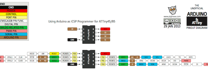
Attiny45 Code
#includeconst int rx = 2; const int tx = 3; SoftwareSerial mySerial(rx, tx); void setup() { mySerial.begin(9600); pinMode(rx,INPUT); pinMode(tx,OUTPUT); } void loop() { mySerial.print("Test Di Comunicazione Tiny45"); delay(1000); mySerial.println(); mySerial.print("Hello"); delay(1000); mySerial.println(); }
ATTINY44 PINOUT
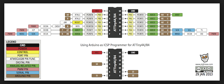
Attiny44 Code
#includeconst int rx = 1; const int tx = 0; SoftwareSerial mySerial(rx, tx); void setup() { mySerial.begin(9600); pinMode(rx,INPUT); pinMode(tx,OUTPUT); } void loop() { mySerial.print("Test Di Comunicazione Tiny44"); delay(1000); mySerial.println(); mySerial.print("Hello"); delay(1000); mySerial.println(); }
Bluethoot Communication
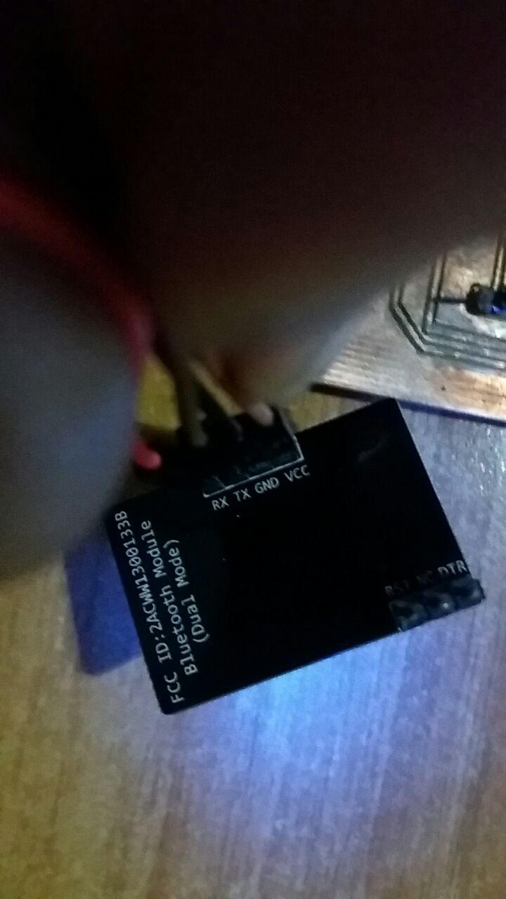
For this experiment I used the fabricated board for my Final project final project and used a commercial bluethoot module; specifically the bluethoot makeblock module, being already in possession of this module, I decided to test this, instead of buying a new one.
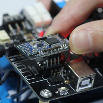
The difference with the hc05
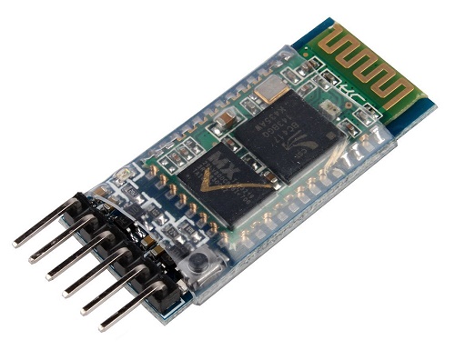
Is in the layout of the pinout, because it is designed to be mounted on makeblock boards, but in practice, this module works exactly like a normal hc05 module
I recommend this tutorial is very interesting on Instructables , which however uses the ATtiny85 microcontroller.
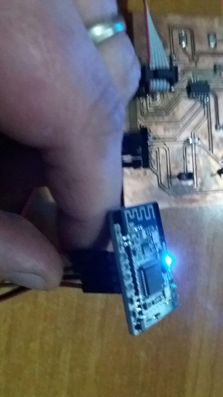
Circuit
I made the pin connections like the diagram I made below
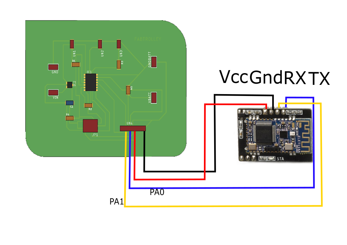
CODE
The code I wrote is to turn on the build-in led of my board through serial communication and the bluetooth module For more information on the Serial Software, refer to this tutorial
#include//Software Serial Port #define RxD 1 #define TxD 0 #define DEBUG_ENABLED 1 SoftwareSerial blueToothSerial(RxD,TxD); int led = 8; void setup() { pinMode(RxD, INPUT); pinMode(TxD, OUTPUT); setupBlueToothConnection(); pinMode(led,OUTPUT); digitalWrite(led,HIGH); } void loop() { int count=0; char recvChar; while(1){ //check if there's any data sent from the remote bluetooth shield if(blueToothSerial.available()){ recvChar = blueToothSerial.read(); count++ ; if(count%2==0) digitalWrite(led,HIGH); else digitalWrite(led,LOW); } } } void setupBlueToothConnection() { blueToothSerial.begin(9600); blueToothSerial.print("\r\n+STWMOD=0\r\n"); //set the bluetooth work in slave mode blueToothSerial.print("\r\n+STNA=Makerblock\r\n"); //set the bluetooth name as "Makerblock" blueToothSerial.print("\r\n+STOAUT=1\r\n"); // Permit Paired device to connect me blueToothSerial.print("\r\n+STAUTO=0\r\n"); // Auto-connection should be forbidden here delay(2000); // This delay is required. //blueToothSerial.print("\r\n+INQ=1\r\n"); //make the slave bluetooth inquirable blueToothSerial.print("bluetooth connected!\n"); delay(2000); // This delay is required. blueToothSerial.flush(); }
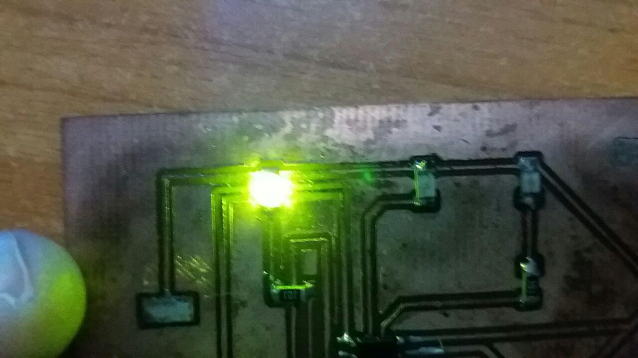
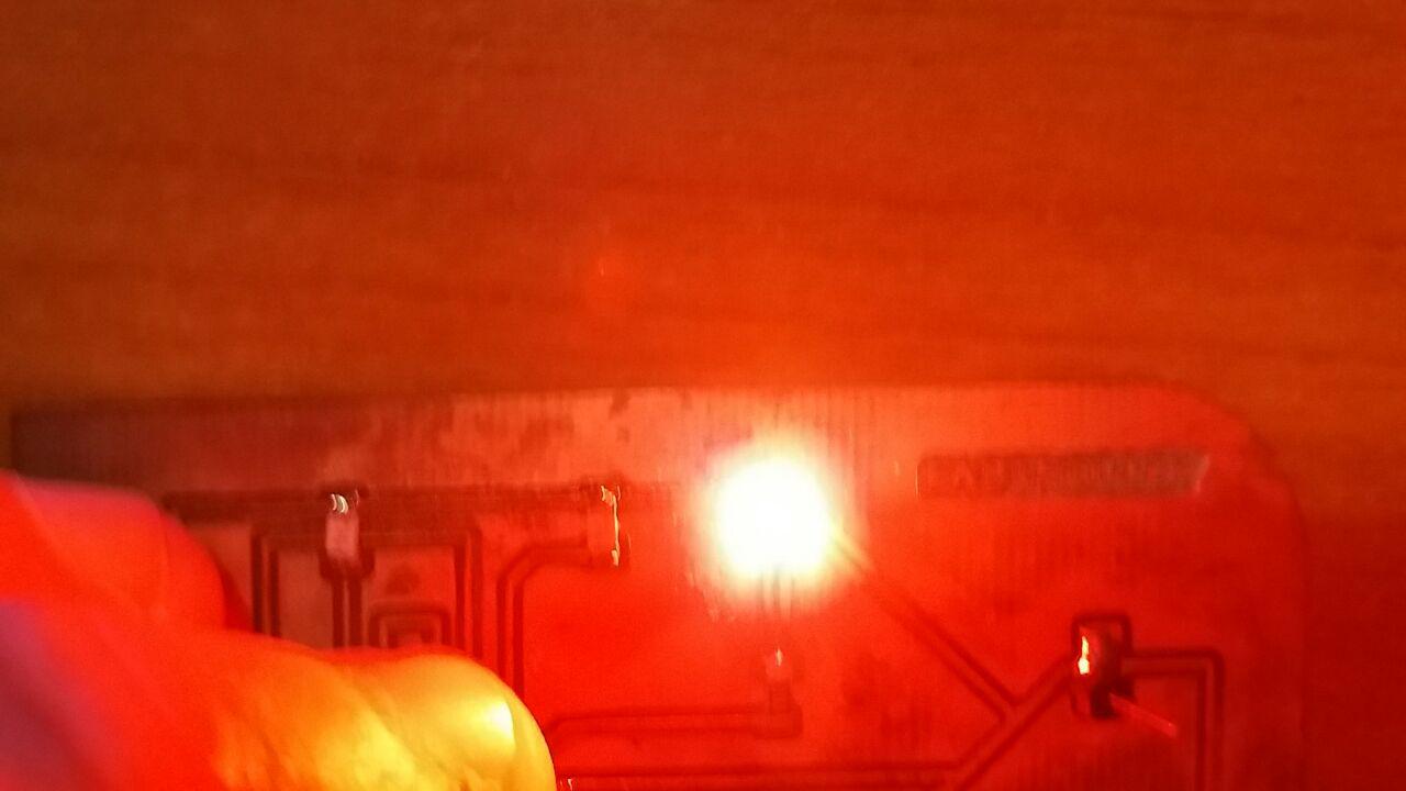
In this way it is possible to switch on the LED build of my card through the bluethoot connection, using the RX and TX pins of the ATtiny44 microcontroller
From the code it is possible to understand that the communication takes place through serial communication, for this it is possible to send the command to turn on (1) or turn off (0) the led, through the arduino terminal, which transmits on the serial port through the bluethoot and sends the command to Attiny44
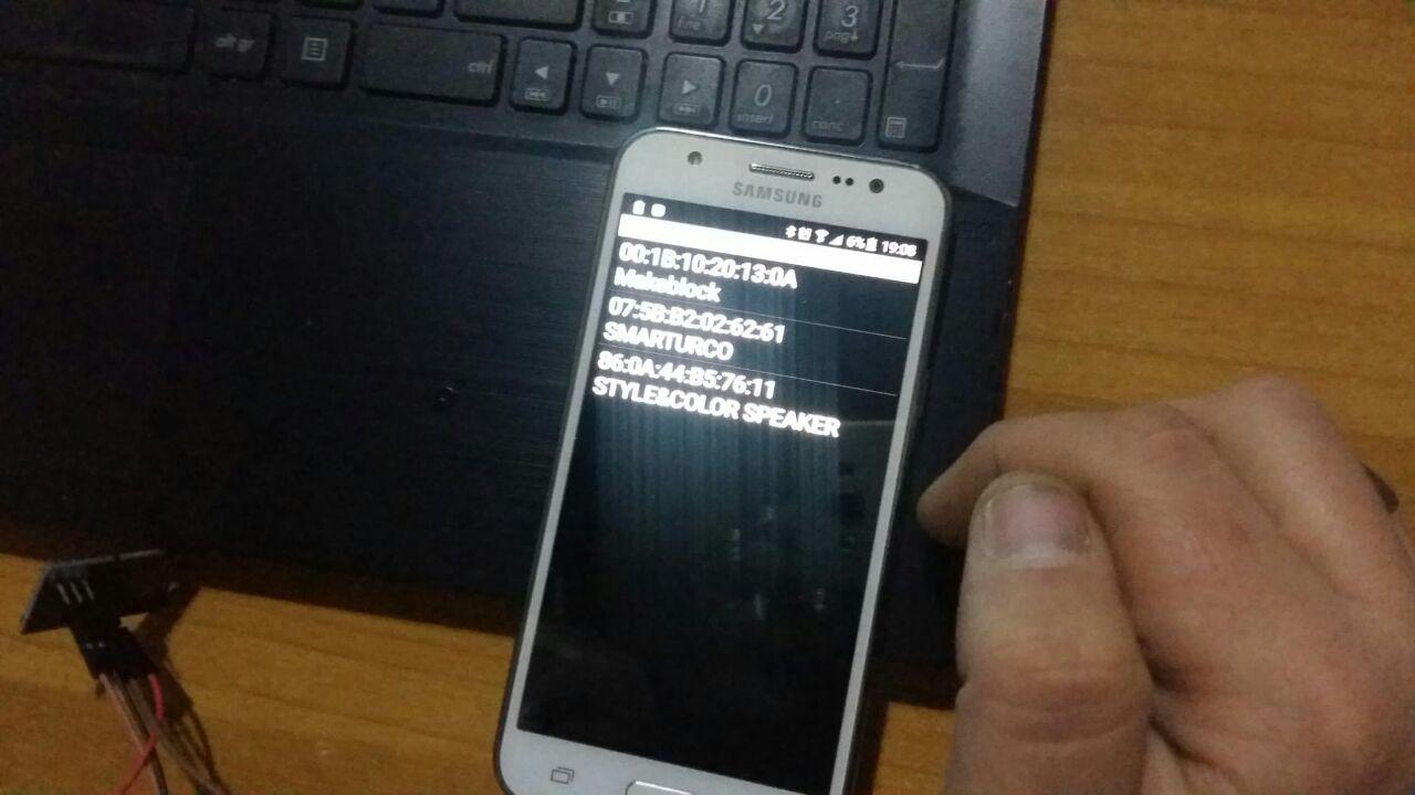
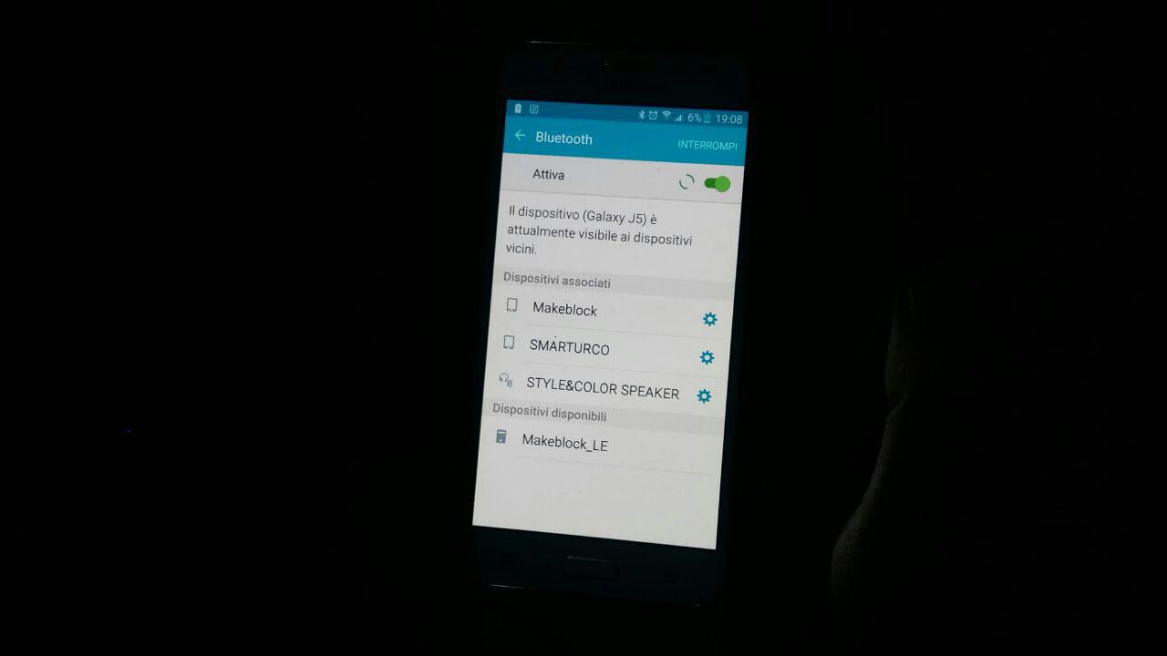
Important:Before sending signals via the Arduino terminal it is necessary to connect, and then associate the PC (activate the bluethoot if deactivated) to the bluetooth module, otherwise the commands will never reach our microcontroller.
For this experiment I also wanted to test the features of APP Inventor , creating an application that installs on Android smartphones
I better describe this procedure in the Interface and Application Programming assignment
After associating my device, I am able to turn on the build-in LED, once the red LED, once the green LED (obviously changing the PIN number in my code)
My Frankenstein boards
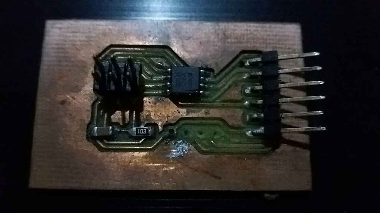
I repeat the experiment with my Frankenstein Board (fabbed during input assignment). By now my boards are dying, they are oxidizing, and on some I have already done several unsolders, but they are still alive!!
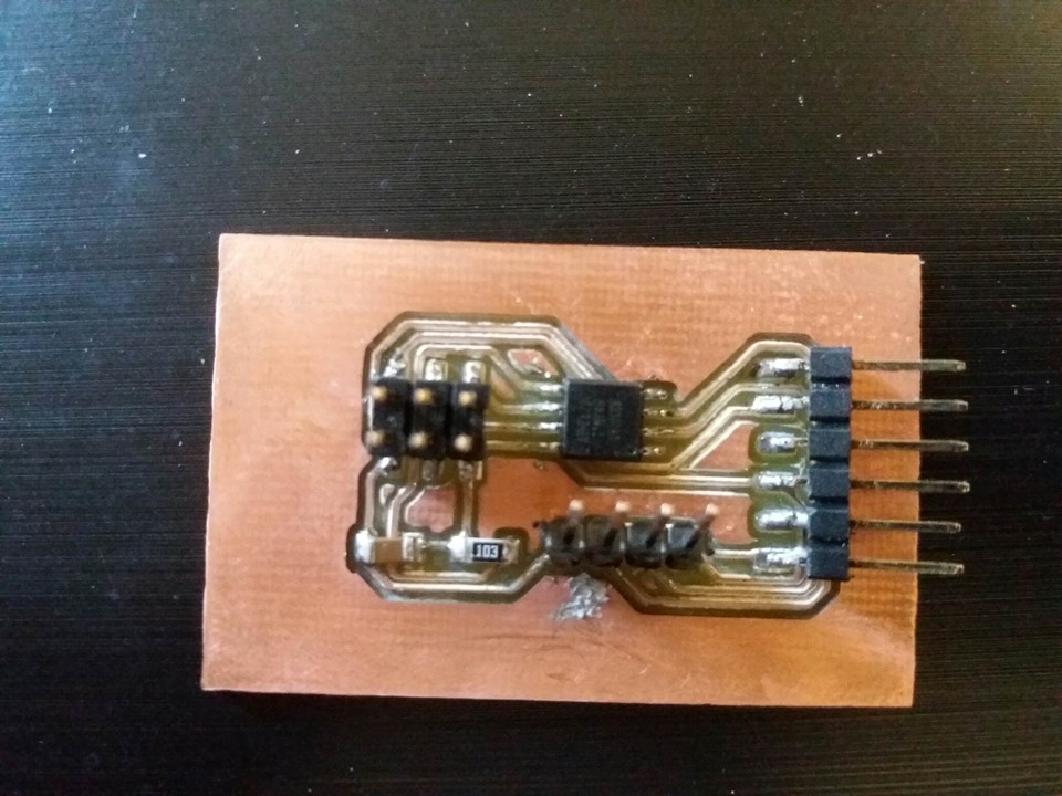
This in my board after many experiments:
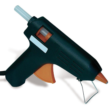
In this regard, I recommend sealing the boards with hot glue so as to delay the oxidation process of the tracks (immediately after manufacture).
This board is equipped with an ATtiny 45 microcontroller and even in this case I am going to connect the TX and RX pins of the bluethoot module with those of my board (PB3 - PB2)
The code used is almost identical, you need to compile the sketch, in order to program the microcontroller with the right settings.
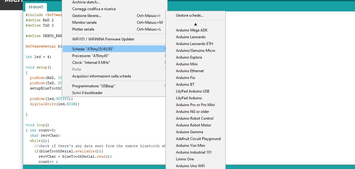
Here the code
#include//Software Serial Port #define RxD 2 #define TxD 3 #define DEBUG_ENABLED 1 SoftwareSerial blueToothSerial(RxD,TxD); int led = 4; void setup() { pinMode(RxD, INPUT); pinMode(TxD, OUTPUT); setupBlueToothConnection(); pinMode(led,OUTPUT); digitalWrite(led,HIGH); } void loop() { int count=0; char recvChar; while(1){ //check if there's any data sent from the remote bluetooth shield if(blueToothSerial.available()){ recvChar = blueToothSerial.read(); count++ ; if(count%2==0) digitalWrite(led,HIGH); else digitalWrite(led,LOW); } } } void setupBlueToothConnection() { blueToothSerial.begin(9600); blueToothSerial.print("\r\n+STWMOD=0\r\n"); //set the bluetooth work in slave mode blueToothSerial.print("\r\n+STNA=Makerblock\r\n"); //set the bluetooth name as "Makerblock" blueToothSerial.print("\r\n+STOAUT=1\r\n"); // Permit Paired device to connect me blueToothSerial.print("\r\n+STAUTO=0\r\n"); // Auto-connection should be forbidden here delay(2000); // This delay is required. //blueToothSerial.print("\r\n+INQ=1\r\n"); //make the slave bluetooth inquirable blueToothSerial.print("bluetooth connected!\n"); delay(2000); // This delay is required. blueToothSerial.flush(); }
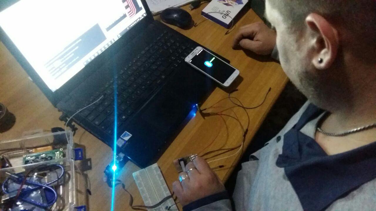
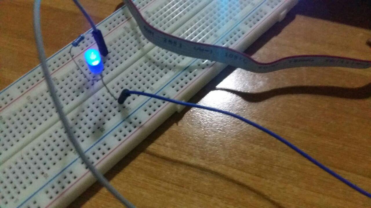
Here you can see the device connected to my smartphone, and through the application created with APP Inventor
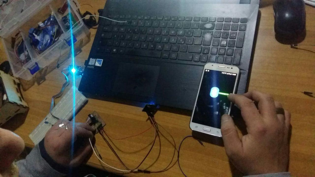
I turn on a led connected to the breaboard (with a 10k resistor in series) that I switch on by shaking the smartphone
Download ZONE
- ArduinoCode
- Tiny 44 Code - FabTrolley Board - Wired Serial Bus
- Tiny 45 Code - Wired Serial Bus
- Bluetooth - Tiny45
- Bluetooth - Tiny45 - Hex File
- Bluetooth - Tiny44
- Bluetooth - Tiny44 -HexFile