Project Development

List of Content
Introduction
Electronic Design & Production
Wiring and Embedded Programming
3D Design & 3D Printing
2D Design & Laser Cutting
Putting all together
Presentation
Introduction
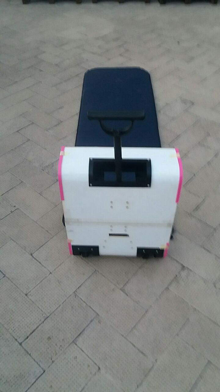
The FabTrolley is a suitcase addressed to a regular traveler, lover of nature and outdoor travel. It is also suitable for the professional who travels frequently, and who does not want to give up a soft bed to rest a few hours at the airport, waiting for the next flight. My suitcase has the characteristic of containing an air bed inside it, which can be inflated using special air pumps installed inside it, and connected with the trolley handle mechanism.
Electronic Design & Production
I Install Eagle from this Link
and i follow this Tutorial and i search information about the component I need
expecially the resistor for the led. It's possible to calculate the resistor we need on this website:
EAGLE (Easily Applicable Graphical Layout Editor) is a flexible and expandable EDA schematic capture, PCB layout, autorouter and CAM program.
EAGLE is popular among hobbyists because of its freeware license and rich availability of component libraries on the web.
Eagle has two windows that are used simultaneously to design a board:
- Schematic (.sch) - logical components
- Board Layout (.brd) for the actual board that we mill
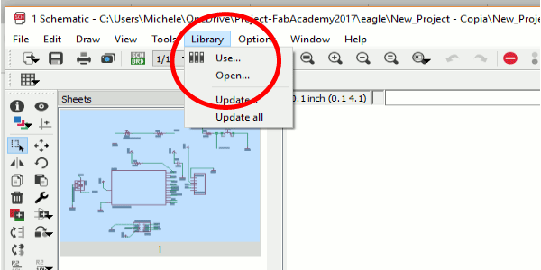
After I installed EAGLE, the first thing which I want to do is Create a New Schematic so I download the fab library (a list of electronic component that any FabAcademy student must have).You can download it
Here. For use the Fab Library, upldoad in this way:
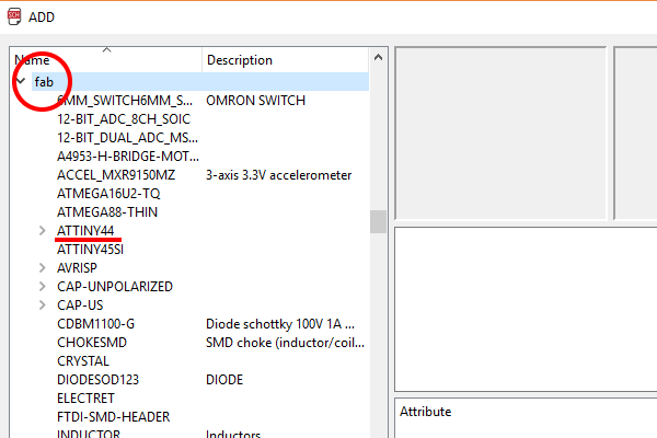
 After do this I have all the component i need in Eagle.
BOM
| Part | Value | Device | Package | Description | |
| C1 | 1uF | CAP-UNPOLARIZEDFAB | C1206FAB | ||
| GND | WIREPADSMD5-2,5 | WIREPADSMD5-2,5 | 5-2,5 | Wire PAD connect wire on PCB | |
| GNDBATT | WIREPADSMD5-2,5 | WIREPADSMD5-2,5 | 5-2,5 | Wire PAD connect wire on PCB | |
| IC1 | ATTINY44-SSU | ATTINY44-SSU | SOIC14 | ||
| IC2 | REGULATORSOT23 | SOT23 | |||
| JP1 | PINHD-2X3-SMD | 2X03SMD | PIN HEADER | ||
| R1 | 100 | RES-US1206FAB | R1206FAB | Resistor (US Symbol) | |
| R2 | 100 | RES-US1206FAB | R1206FAB | Resistor (US Symbol) | |
| R3 | 100 | RES-US1206FAB | R1206FAB | Resistor (US Symbol) | |
| R4 | 10k | RES-US1206FAB | R1206FAB | Resistor (US Symbol) | |
| R5 | 10k | RES-US1206FAB | R1206FAB | Resistor (US Symbol) | |
| U$1 | LEDFAB1206 | LEDFAB1206 | LED1206FAB | LED | |
| U$2 | LEDFAB1206 | LEDFAB1206 | LED1206FAB | LED | |
| U$3 | LEDFAB1206 | LEDFAB1206 | LED1206FAB | LED | |
| U$4 | FTDI-SMD-HEADER | FTDI-SMD-HEADER | 1X06SMD | ||
| VBATT | WIREPADSMD5-2,5 | WIREPADSMD5-2,5 | 5-2,5 | Wire PAD connect wire on PCB | |
| VIN | WIREPADSMD5-2,5 | WIREPADSMD5-2,5 | 5-2,5 | Wire PAD connect wire on PCB |
Attiny 44
For undertand how use better the Attiny 44 I read the datasheet for undertand the Pins and his internal architecture:
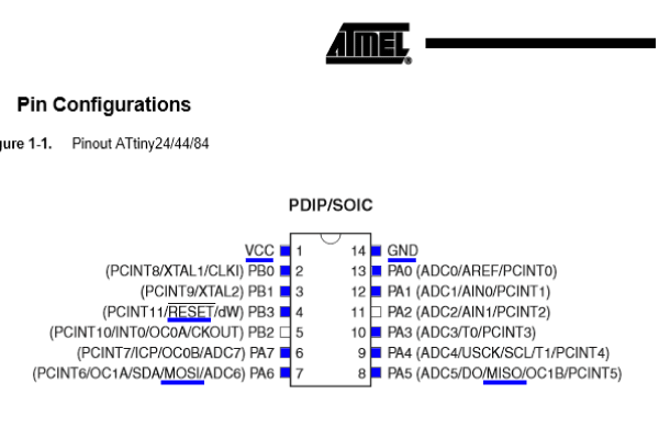 SCK(Serial Clock): Programming clock, generated by the In-System Programmer (Master)
MOSI(Master Out - Slave In ): Communication line from In-System Programmer (Master) to target AVR being programmed (Slave )
MISO( Master In - Slave Out ): Communication line from target AVR (Slave) to In- System Programmer (Master)
RST(Reset): To enable In-System Programming, the target AVR Reset must be active. To simplify this, the In-System Programmer should control AVR Reset
GND(Ground): Common Ground
The Schematic

For add e move the component:
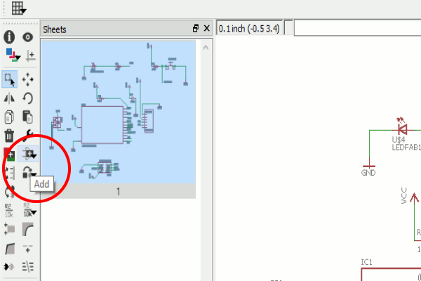
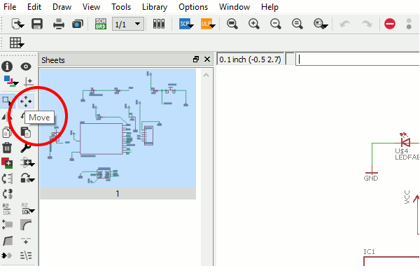
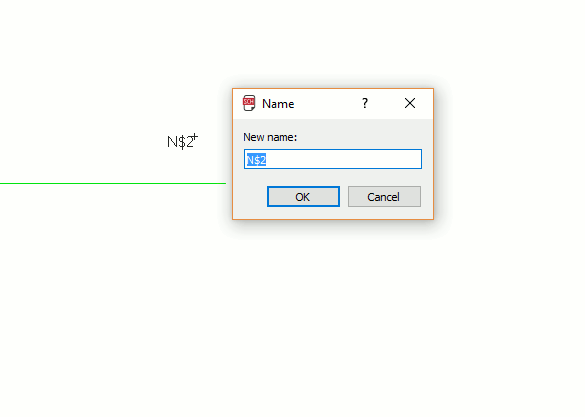
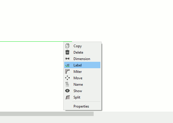
for connect the component I use the label function and I connect to the component i want using the name funcion
After do this i swith from schematic to board and I move the component where i want
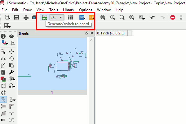
After move the component I set the Design rules for my trace width and distance:
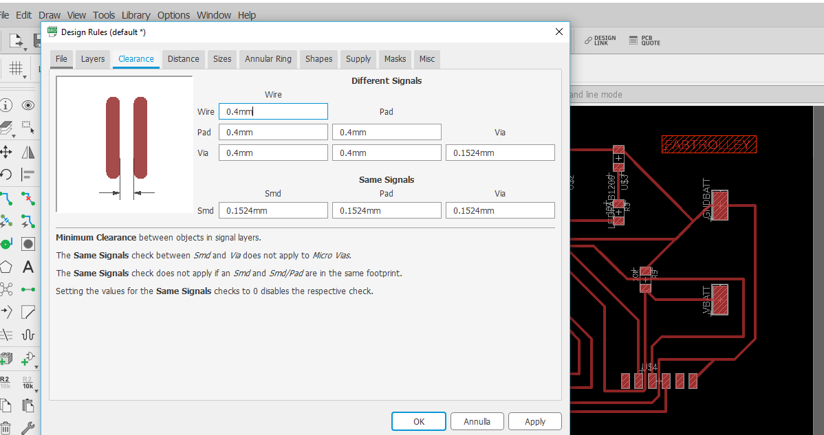
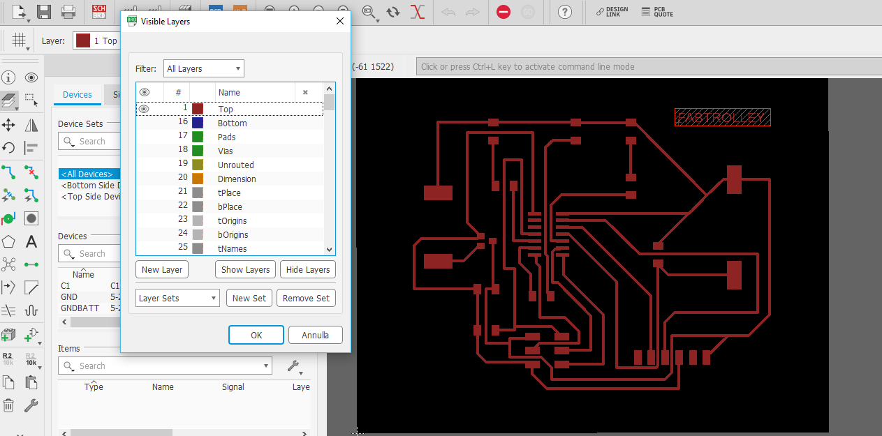
After routed my board, I created the outline for cutting the board

I select only the layers I need (one at a time)
and I export the images to 1000dpi monochrome, before the top layer and then the outline
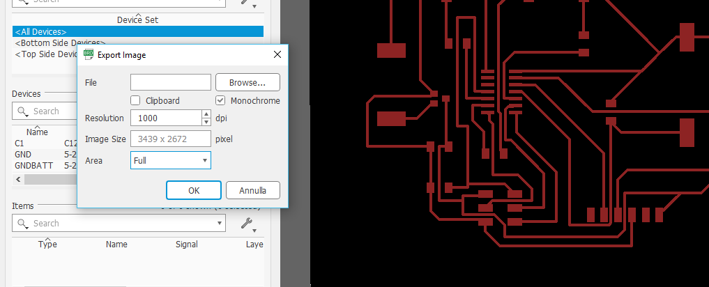
Trace

Cut

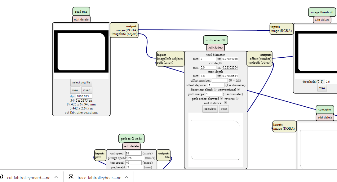
To generate the gcode I used the fabmodules by importing the images that I generated previously
I chose the mill 2d png option
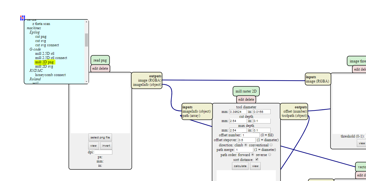
So my final settings look like this:
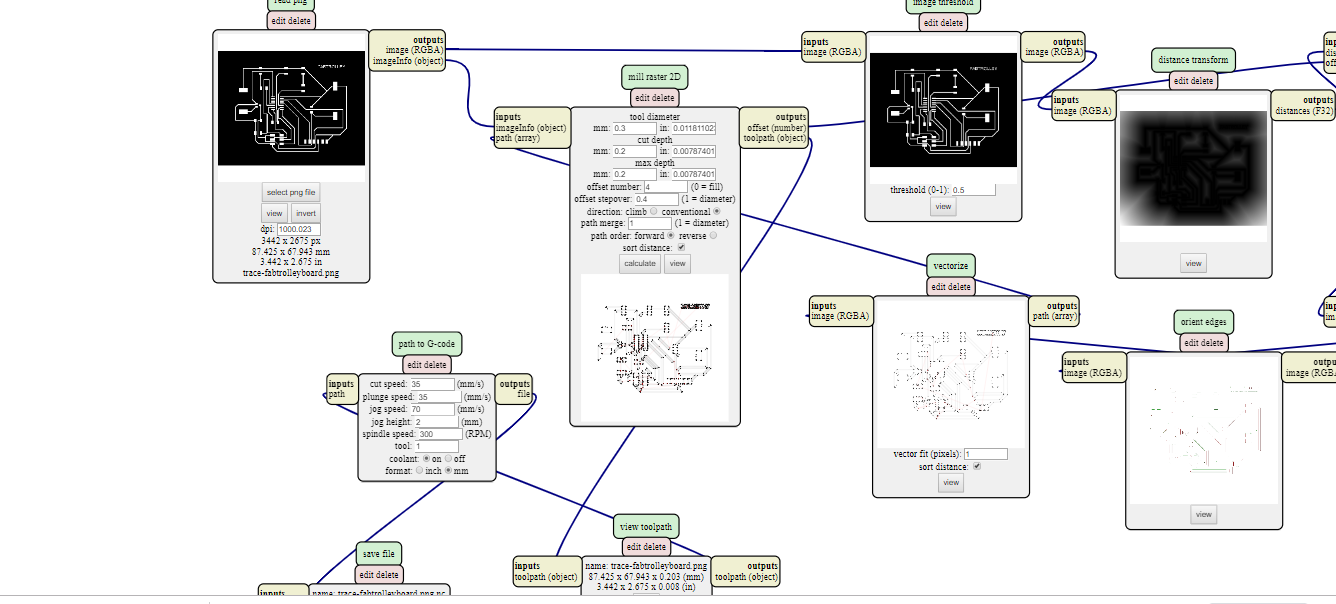
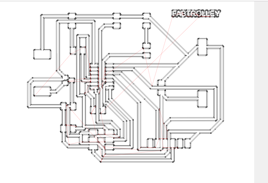
My settings to cut the board
After this I downloaded the software to control my GRBL based machine.
here you can download the GRBL control software
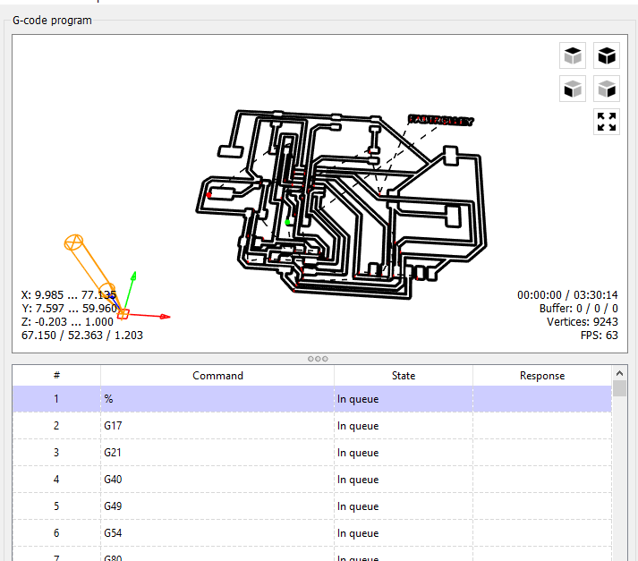
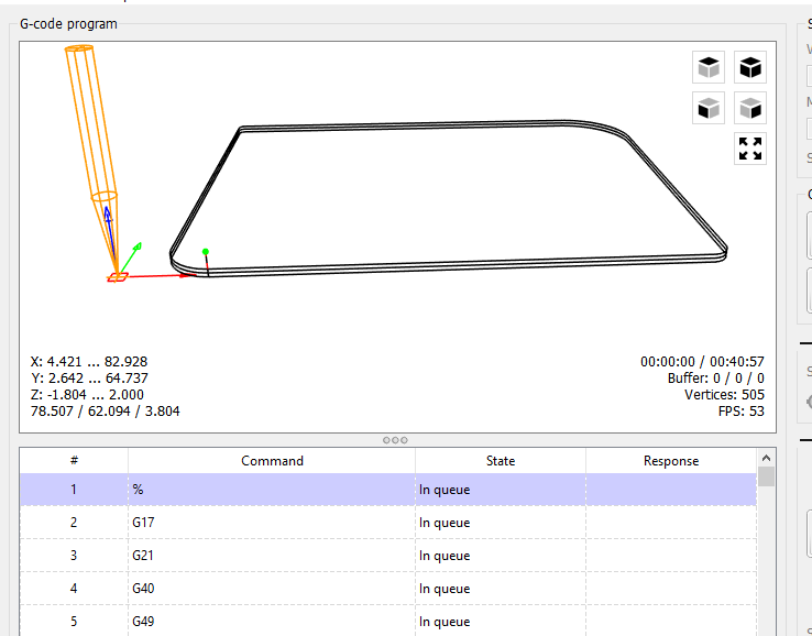
The cnc used by me is a machine sold in kit to be assembled, and has a grbl board with a useful work surface of 300x180mm and a spindle height of 45mm.
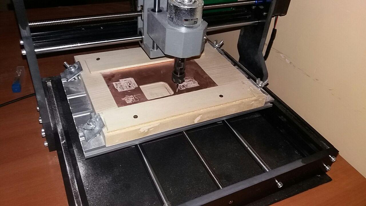
This is the final Relsult of the board:

There are many other software for the preparation of gcode, in the "Input" assignment I show how to use flatcam instead of the fabmods and MACH3 instead of grbl control
And now Let's solder this!
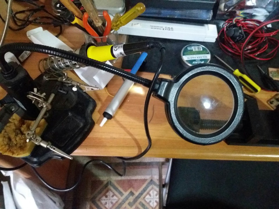
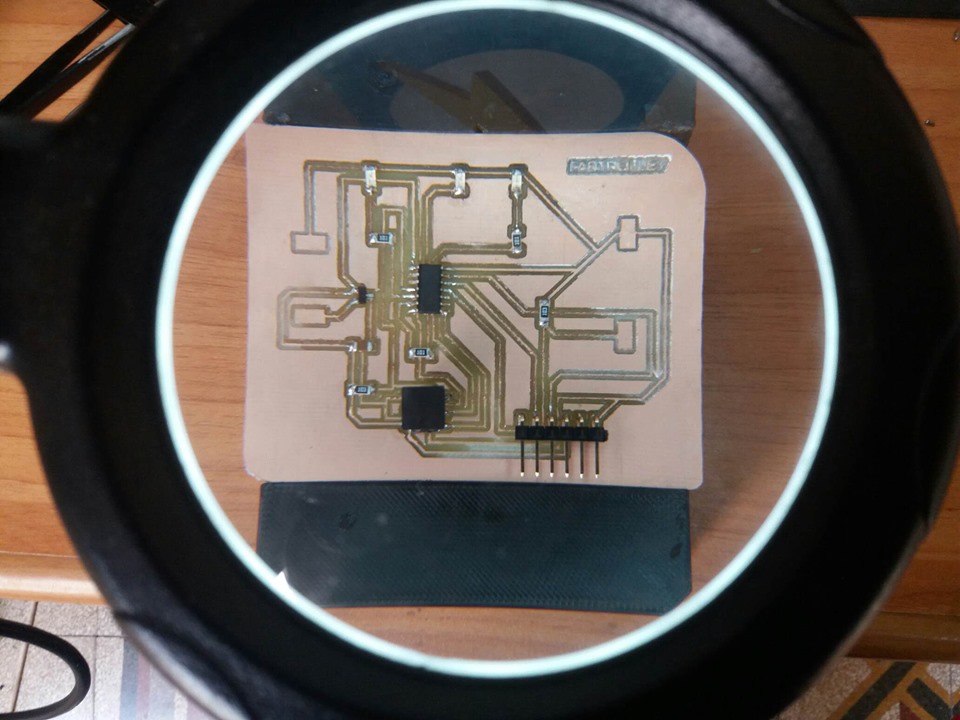
In order to make sure that I soldered everything in a right way, after each component soldered, I used the multimeter to check if there is conductivity between the component and the traces.
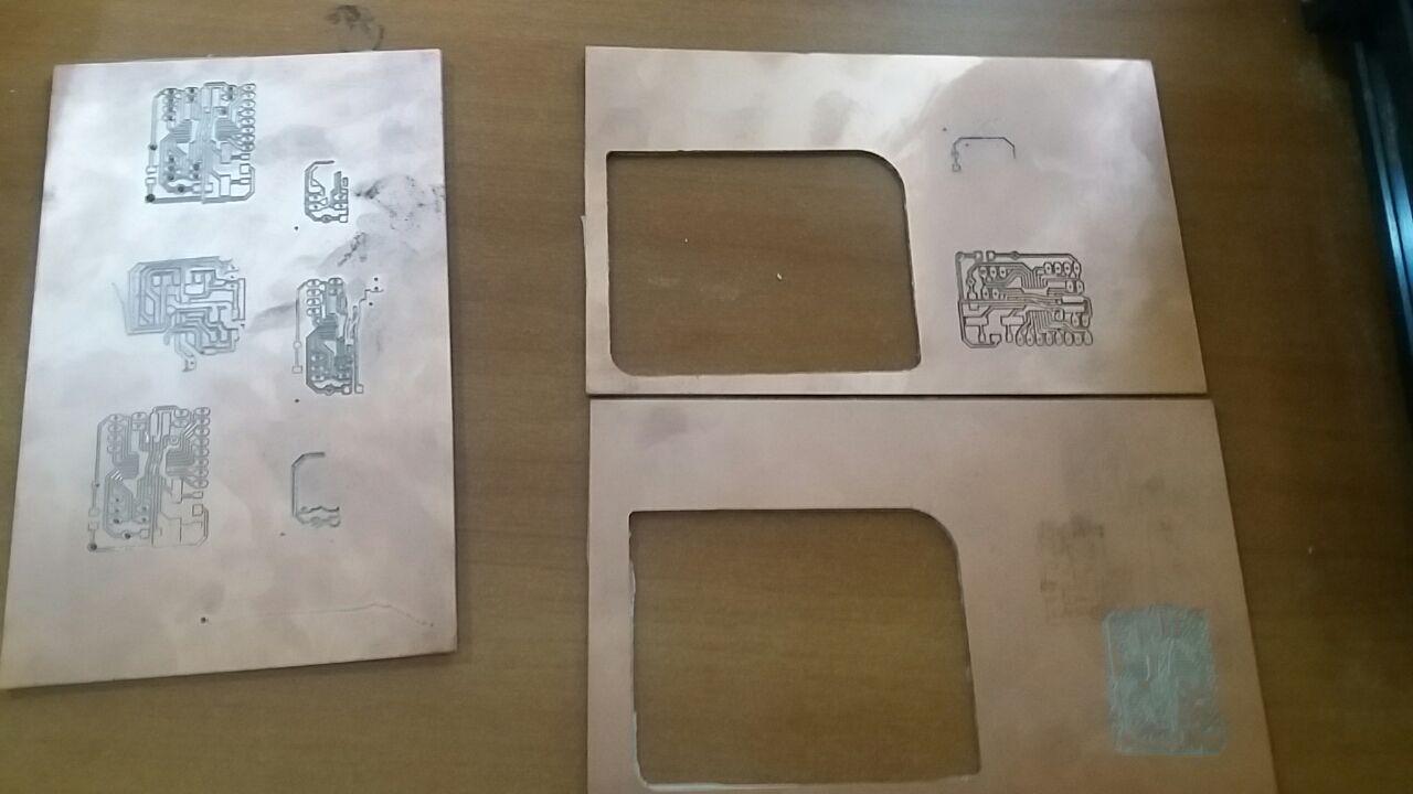
A photo for those who believe it is easy
Download ZONE
Wiring and Embedded Programming
To program my board I used Arduino IDE and Avrdudess
As a programmer I used a USBASP ISP I choose it as a programmer (in the Arduino IDE) after installing the drivers using the Zadig software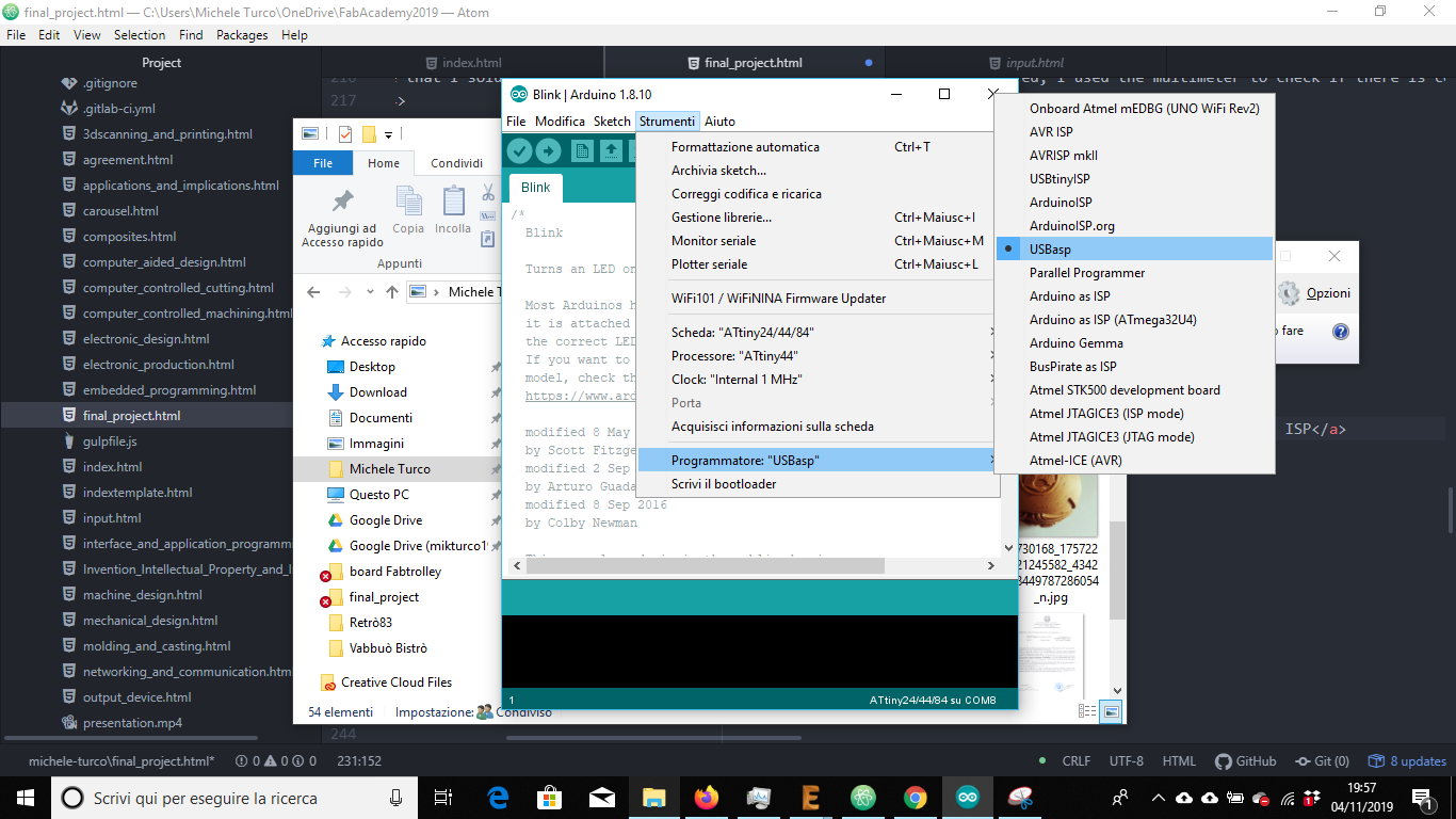
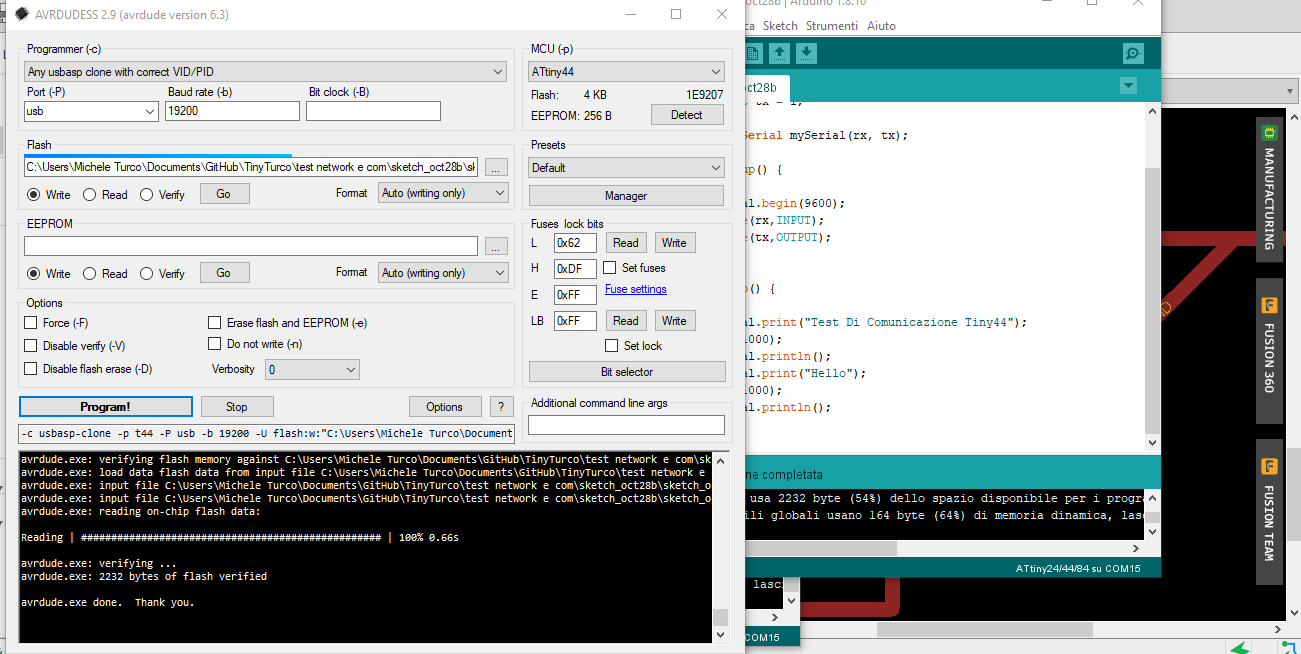
I already had the chance to test my board to complete "Networking and Communications" and it is therefore ready to be programmed for my FabTrolley
TEST
ATTINY44 PINOUT
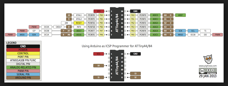
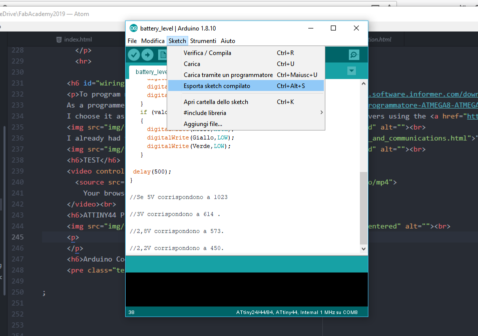
I export the compiled scketch from Arduino IDE so that I can upload it to my board via avrdudess
Arduino Code
int valore;
int Rosso=3;
int Giallo=7;
int Verde=8;

void setup()
 {
  pinMode(3,OUTPUT);
  pinMode(7,OUTPUT);
  pinMode(8,OUTPUT);
 }
void loop()
{
 delay(100);
 valore=analogRead(2);
 if (valore>614)
   {
     digitalWrite(Rosso,LOW);
     digitalWrite(Giallo,LOW);
     digitalWrite(Verde,HIGH);
   }
   if ((valore<614)&&(valore >=450))
   {
     digitalWrite(Rosso,LOW);
     digitalWrite(Giallo,HIGH);
     digitalWrite(Verde,LOW);
   }
   if (valore<450)
   {
     digitalWrite(Rosso,HIGH);
     digitalWrite(Giallo,LOW);
     digitalWrite(Verde,LOW);
   }

 delay(500);
}

//Se 5V corrispondono a 1023

//3V corrispondono a 614 .

//2,8V corrispondono a 573.

//2,2V corrispondono a 450.
Battery level Test
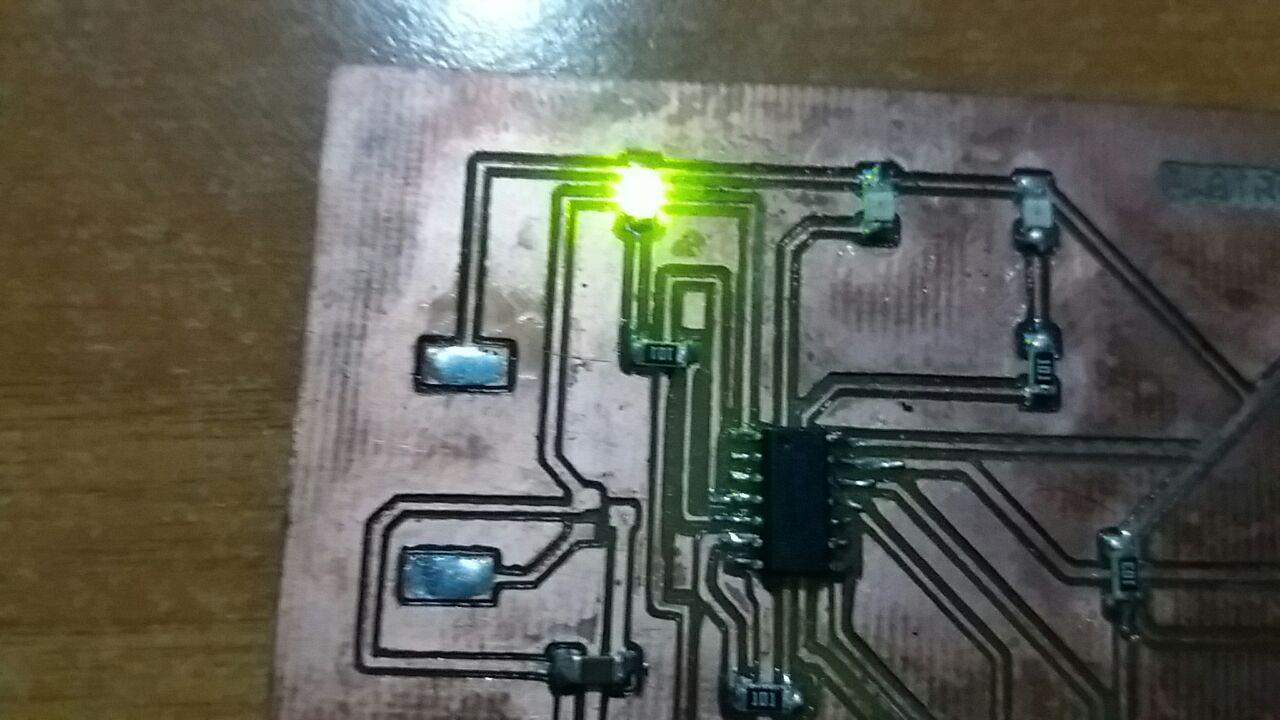
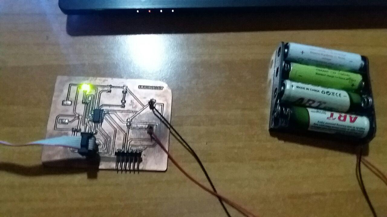
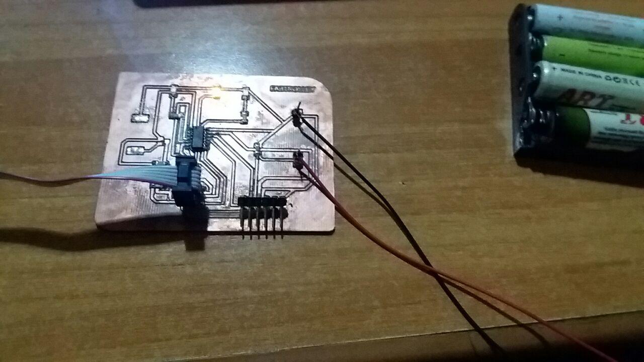
I did a test of my board with the sketch just completed. Depending on the battery charge level, the assigned LED should light up. That is: Green for the Maximum Battery Level, Yellow for an Intermediate Level and Red for a Low Battery Level
Case1 - High level Battery - Green Led
Case2 - Mid level Battery - Yellow Led
Case3 - Low level Battery - Red Led
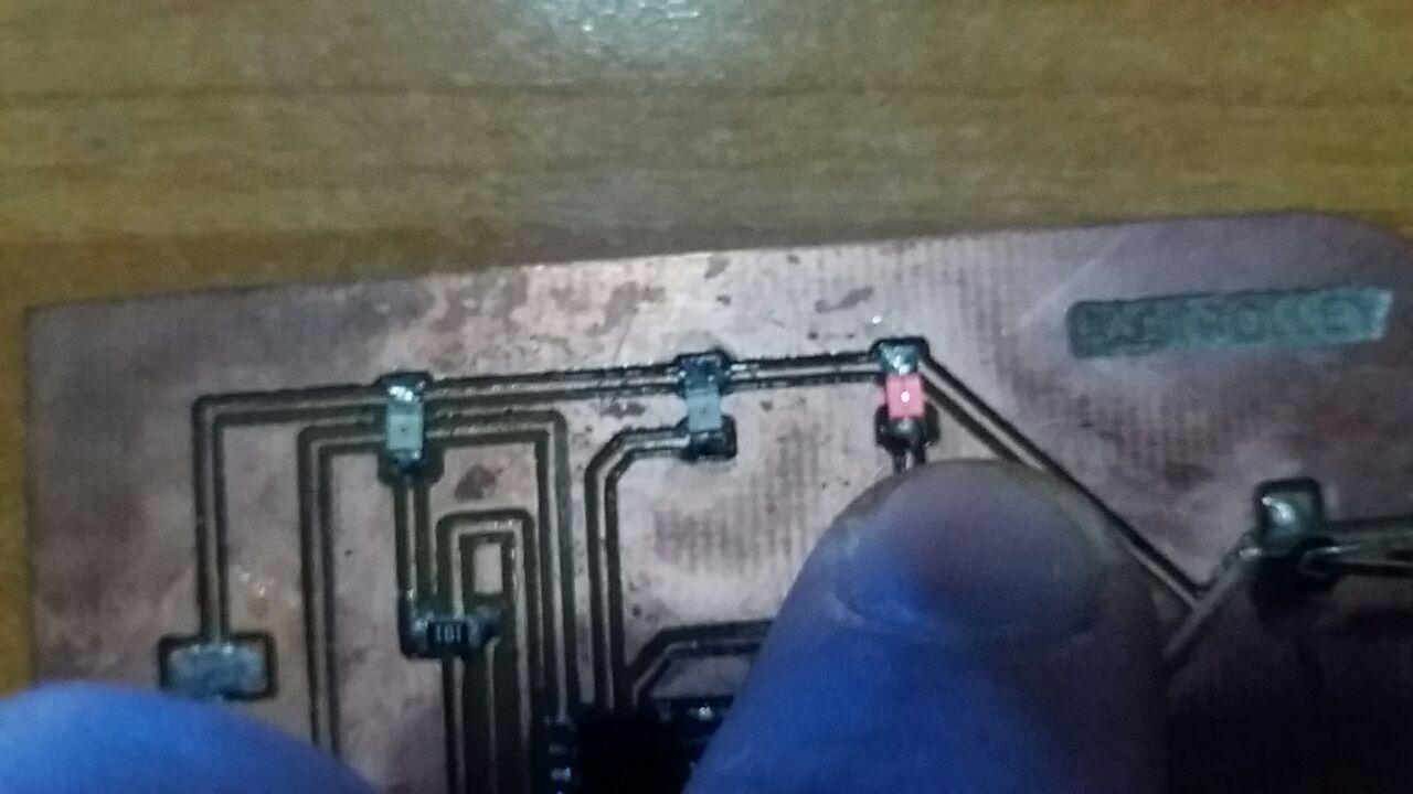
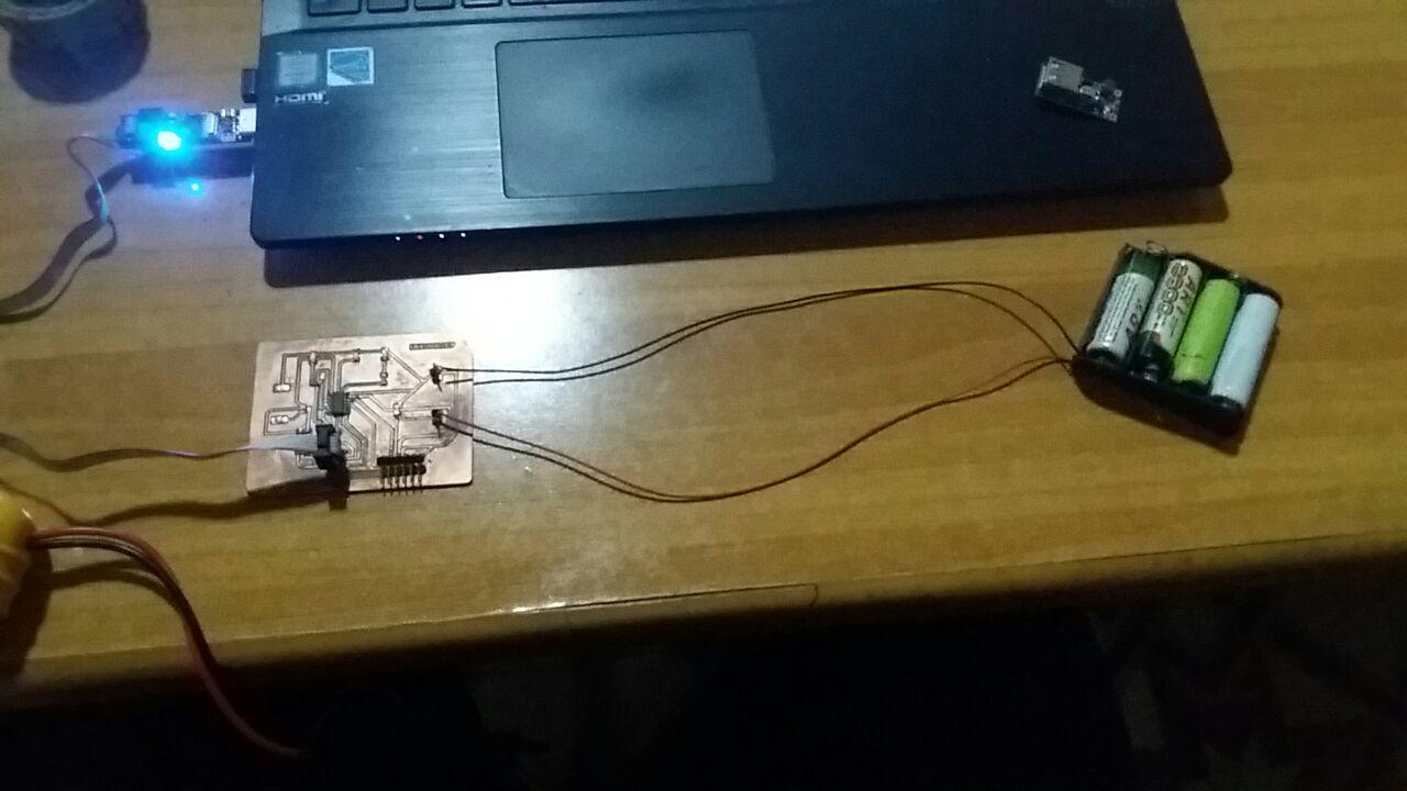
I will make the electrical connections as in the scheme I made:

Difference between putting the batteries in series or in parallel:
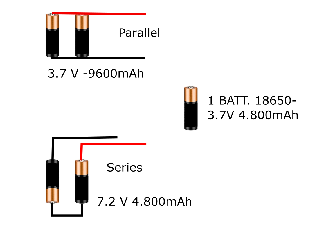
this is because in most portable electronic devices on the market (eg smartphones) they need a voltage of 5V. At the same time it is necessary to have a sufficiently high level of recharge, in order to guarantee the device a complete charge in an acceptable time, for this reason our battery pack will have 4800mAh and 5V of voltage
Download ZONE
3D Design & 3D Printing
For 3D design, I used Autodesk Fusion 360 which as I mentioned before in other assignments, is one of my favourite CAD software!
I will not go too much into details of how to create simple shapes, and extrude objects, all this could be found during my Computer-Aided Designweek,
where I learned how to use diferent softwares.
I am very happy to have studied the movement of the various components of the Fabtrolley with this software and how it helped me to design well the functioning of the mechanical parts and gears to recharge the dynamo during the movement of the suitcase
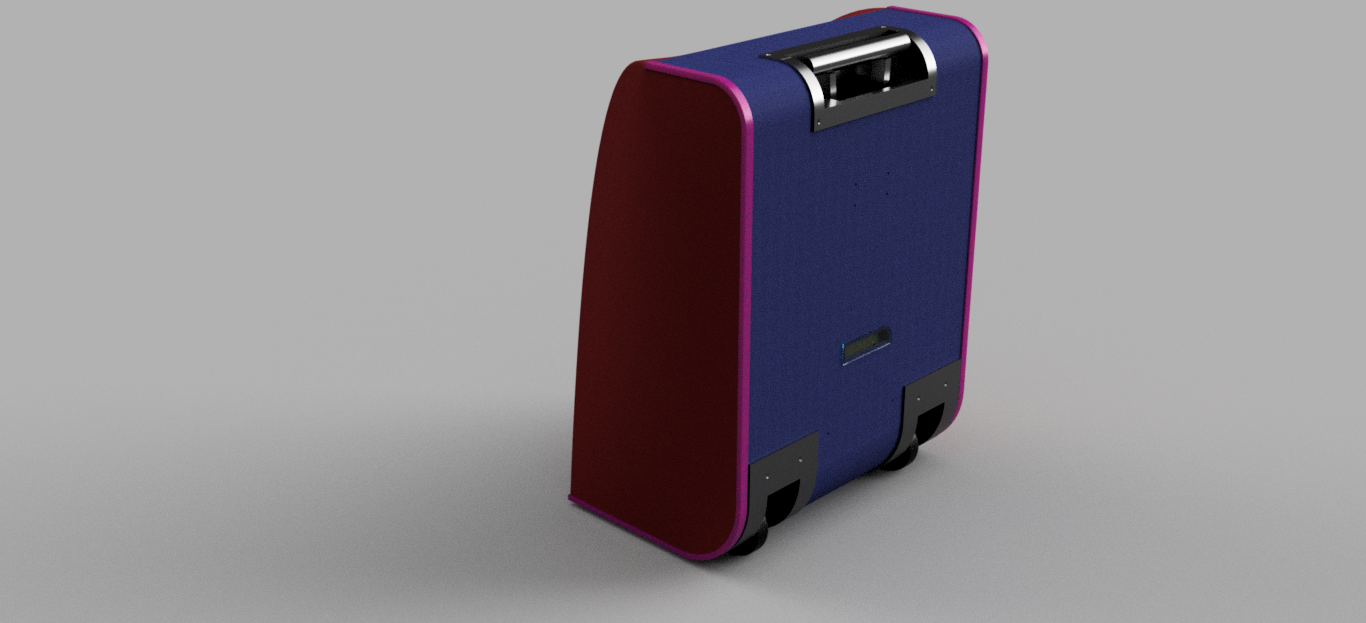
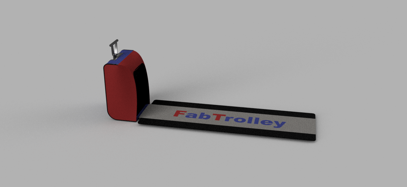
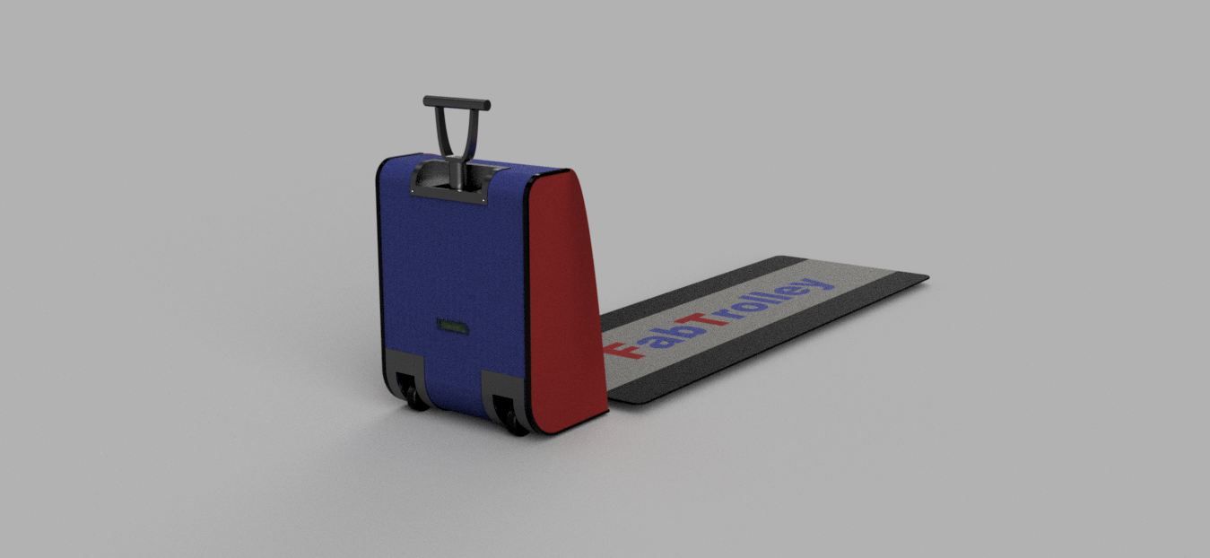
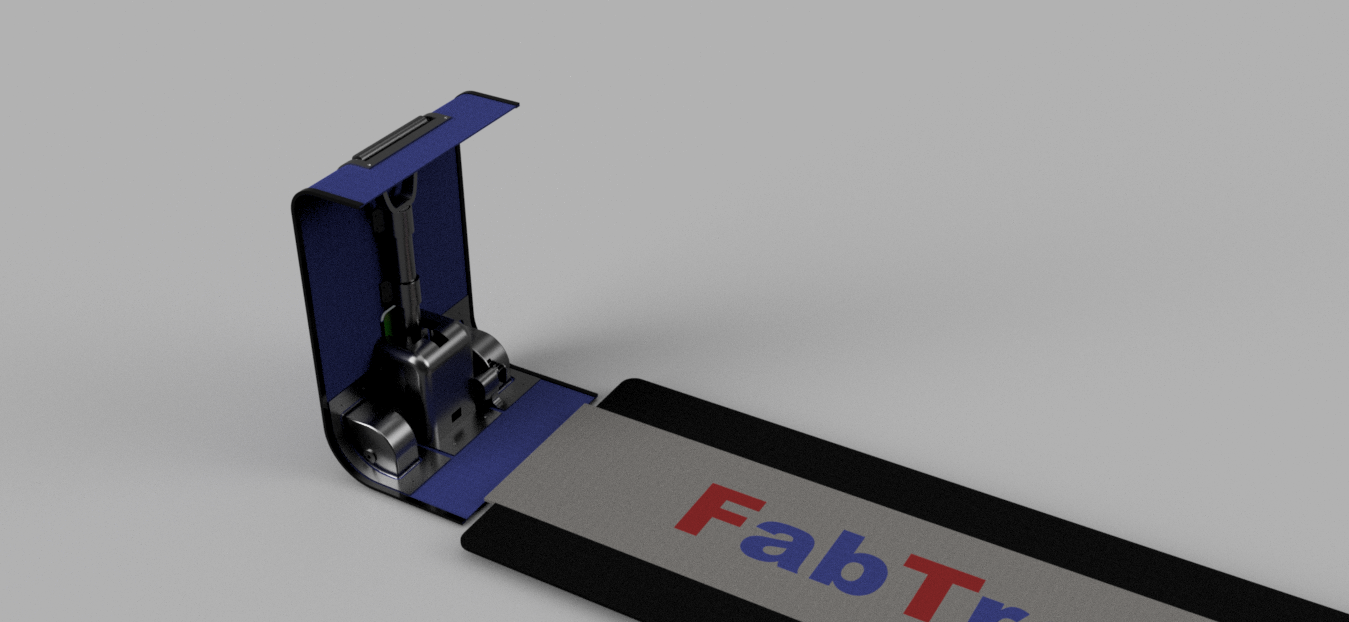
I created a folder on the Cloud Fusion 360 containing all the components and images of my project.
Then a little trick, I charge the board I designed with Eagle inside the Fusion 360 so that I could better fit it into my suitcase
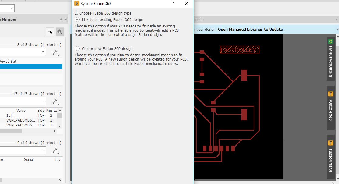
Here the board on my Fusion360 Cloud
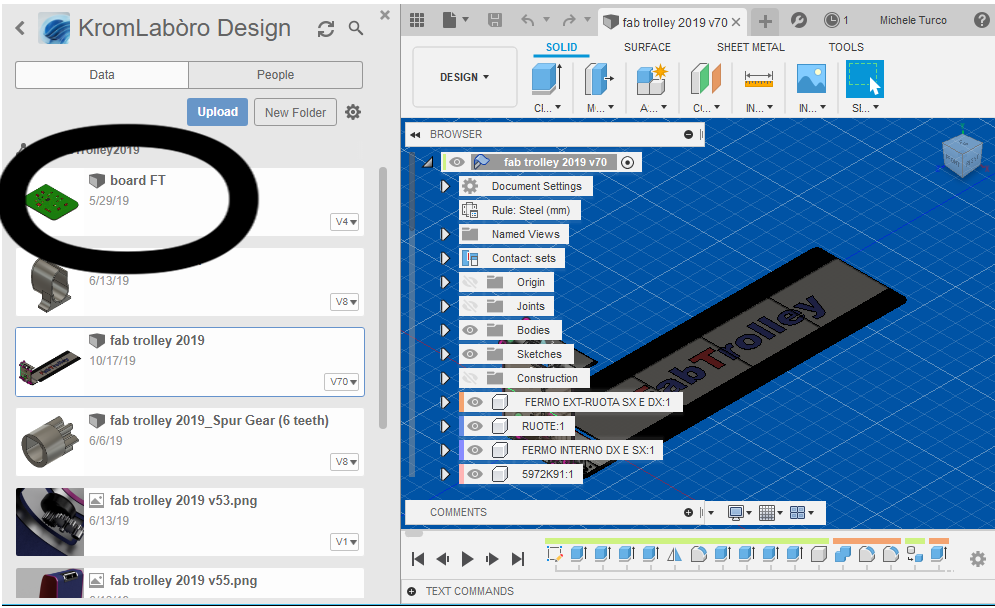
After doing this I prepare to draw the frame of my trolley, considering the fact that I will use 2mm cardboard that I will later fold to the desired shape.
to have a design as faithful to reality as possible, I used the Fusion 360 "sheet metal" mode which allows you to fold and unfold solids created along predetermined bends
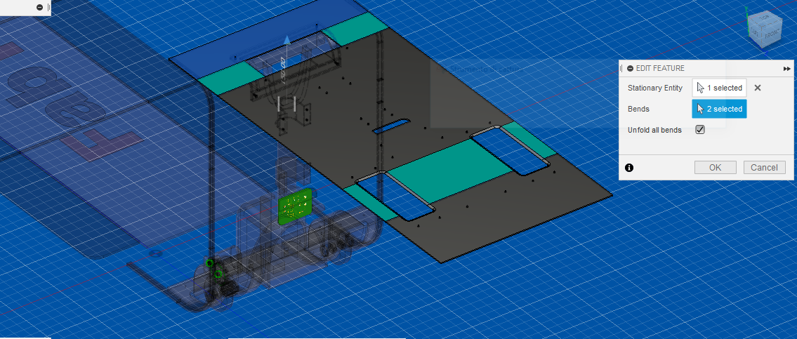
here you can follow an Autodesk Tutorial on how to use the Fusion360 Sheet metal mode.
I will return later (in the 2D-Laser Cutting section) on the question of the frame.
The wheels
The next step is to design the trolley wheel system which will give rigidity to the suitcase and above all the ability to move
The system I intend to use is adopted on many trolleys currently on the market. Here an image:
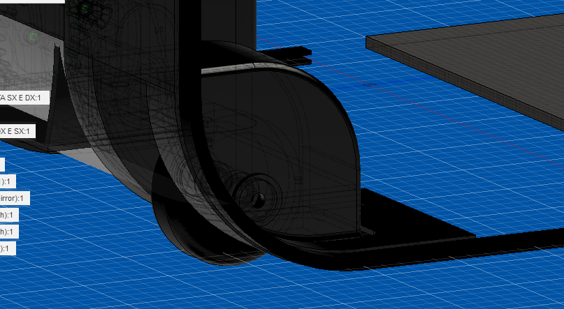
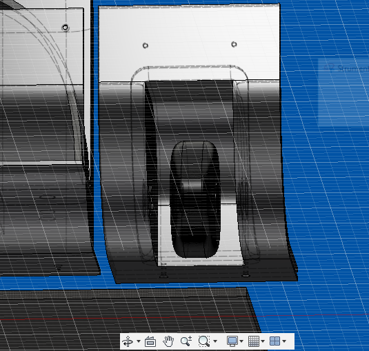
After printing the wheels I inserted the 608z bearings inside them. a small trick in Fusion360 is to use the most common industrial components in the project, such as bearings, screws, nuts, bolts, etc. In fusion360 it is possible to insert such components in this way:
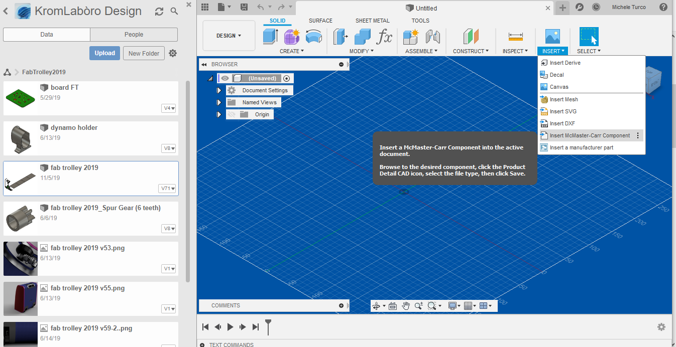
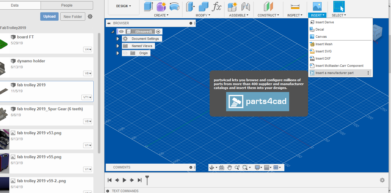
The wheels and gears are the only pieces that I have decided to print in ABS (3DFUel) , in order to have a very high resistance. I printed the wheels with the Zortrax M200 aviable in our KromLabòro Caserta FabLab .
I used the following settings within the Zsuite slicer:
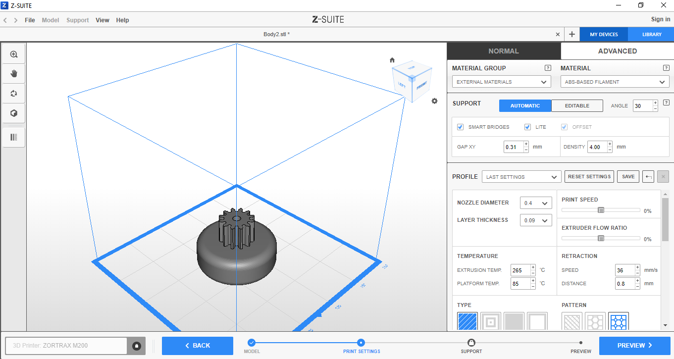
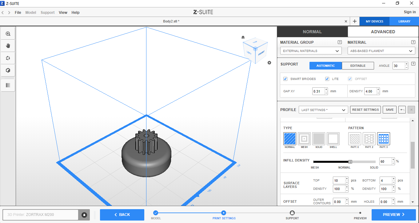
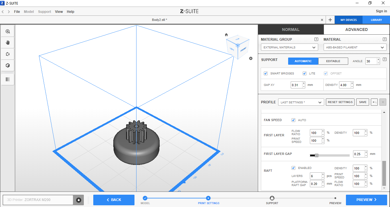
Here the wheels looks like:
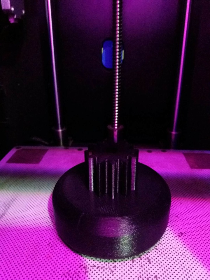
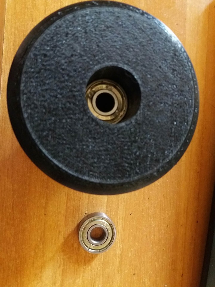
each wheel will contain 2 bearings at a time
The gear system - Mechanical Design
To transmit the movement of the wheels to the dynamo, so that it can generate current to charge the battery pack, I created a system of gears and toothed wheels.
First, I was interested in figuring out how to transmit motion in the right direction, how many cogwheels I need and how big they must be to transmit enough rotation to the dynamo to generate current
Thanks to Gear Generator I was able to find the right solution for my needs. here is how it looks
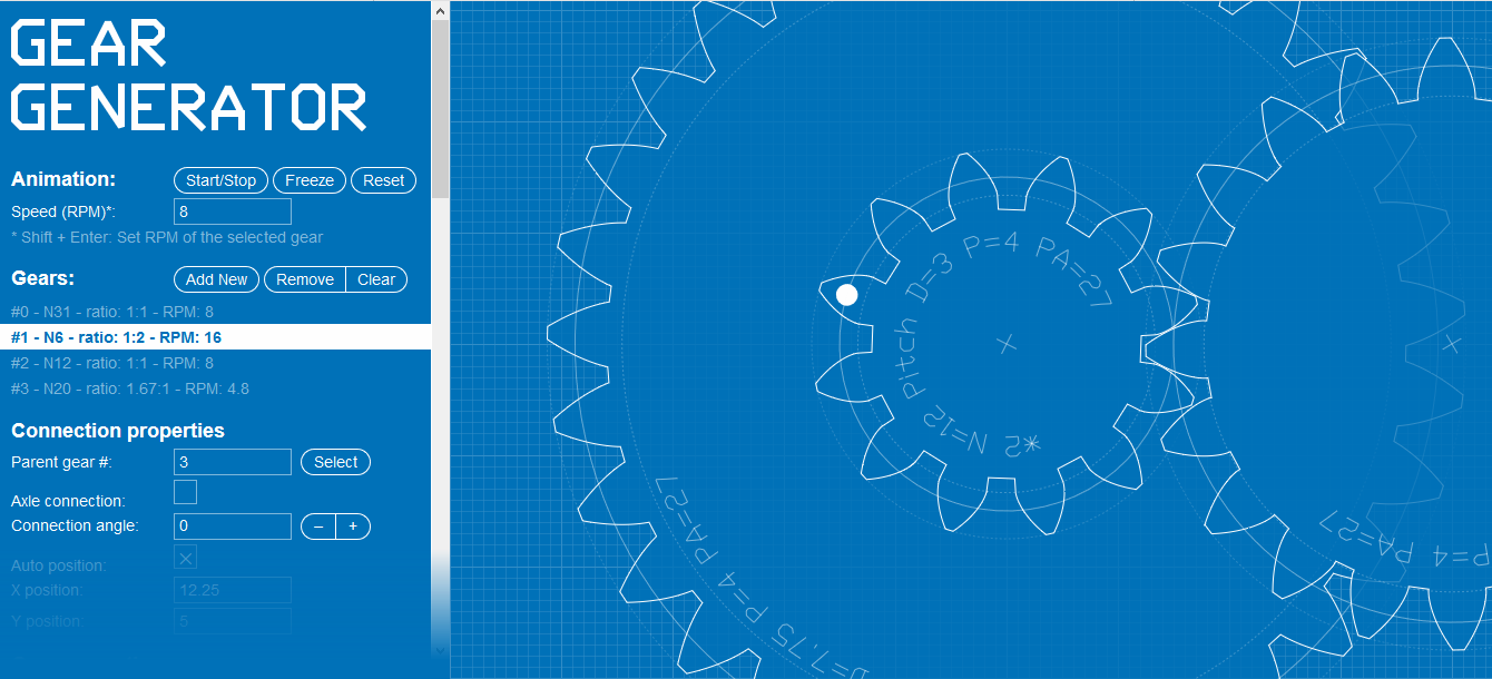
You can also save your work by saving the link like i did, or with a small donation download the file.
In Fusion 360 you can build these gears with the "Spur gear" plug-in that you can download from the official Autodesk website.and it is possible to open it in the program in this way:
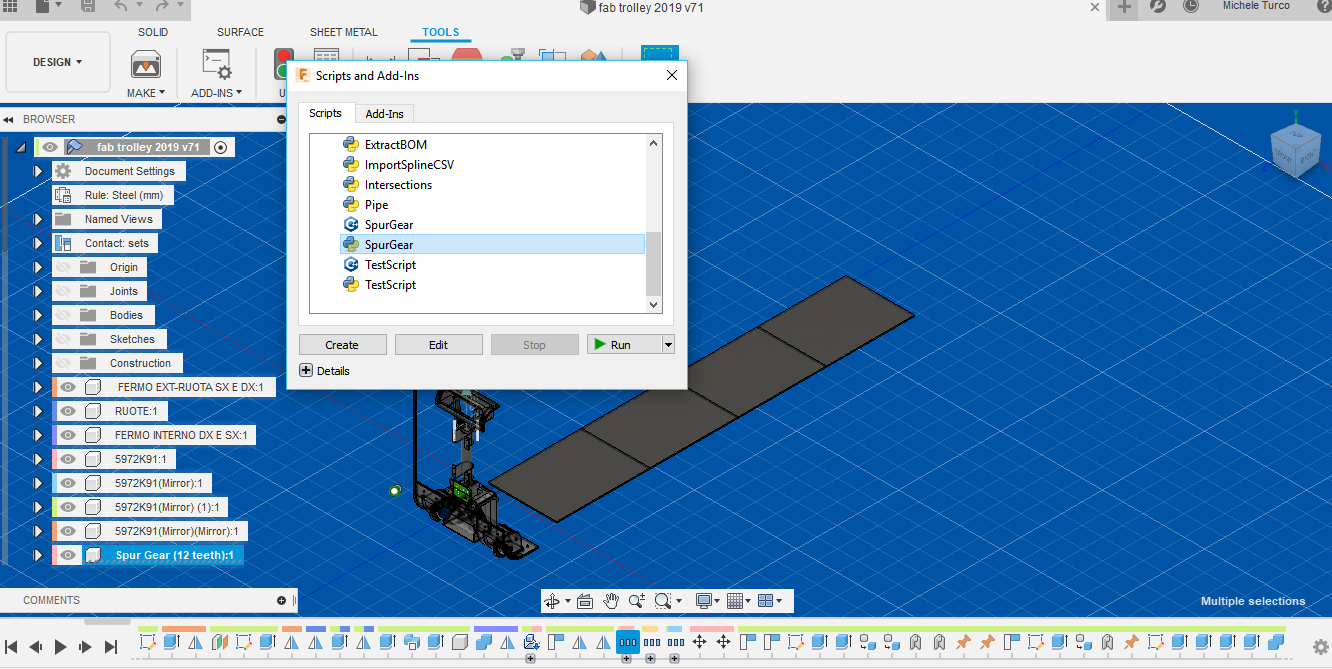
that's how gears look like
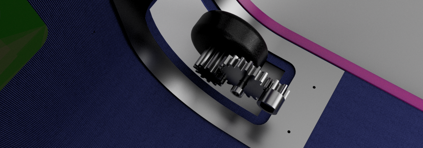
I studied the movement of the gears using the "Joint" and "Contact Point" functions of the Fusion 360 and have the certainty of having a smooth movement with the wheels well fitted together
The pieces on which I had no doubt more problems in printing them are the wheel covers.
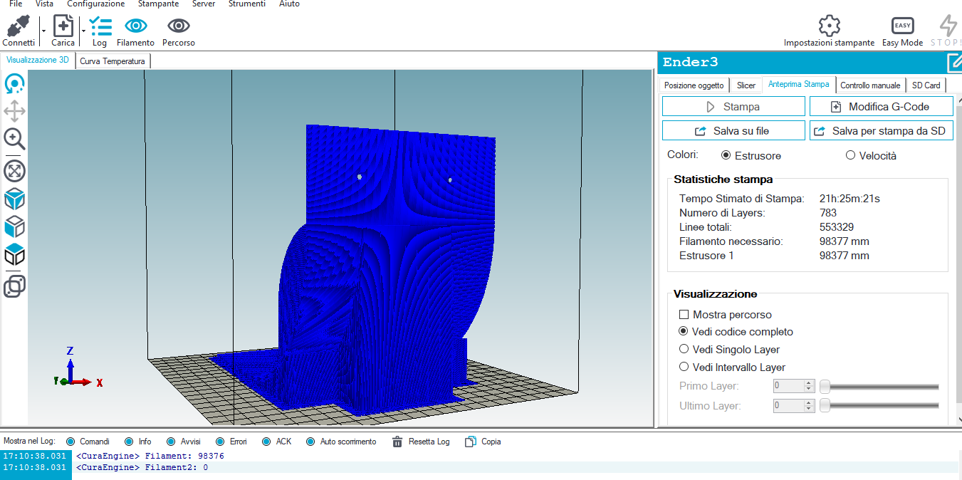
Unfortunately for the very complex shape of the pieces they moved from the printing plane. Using the plaPro 3D fuel and wax glue, I solved the problem. Similar situation for the parts of the handle cover.
I am satisfied with the result, and I painted all the pieces of black color, to make everything uniform.
A photo for those who believe it is easy
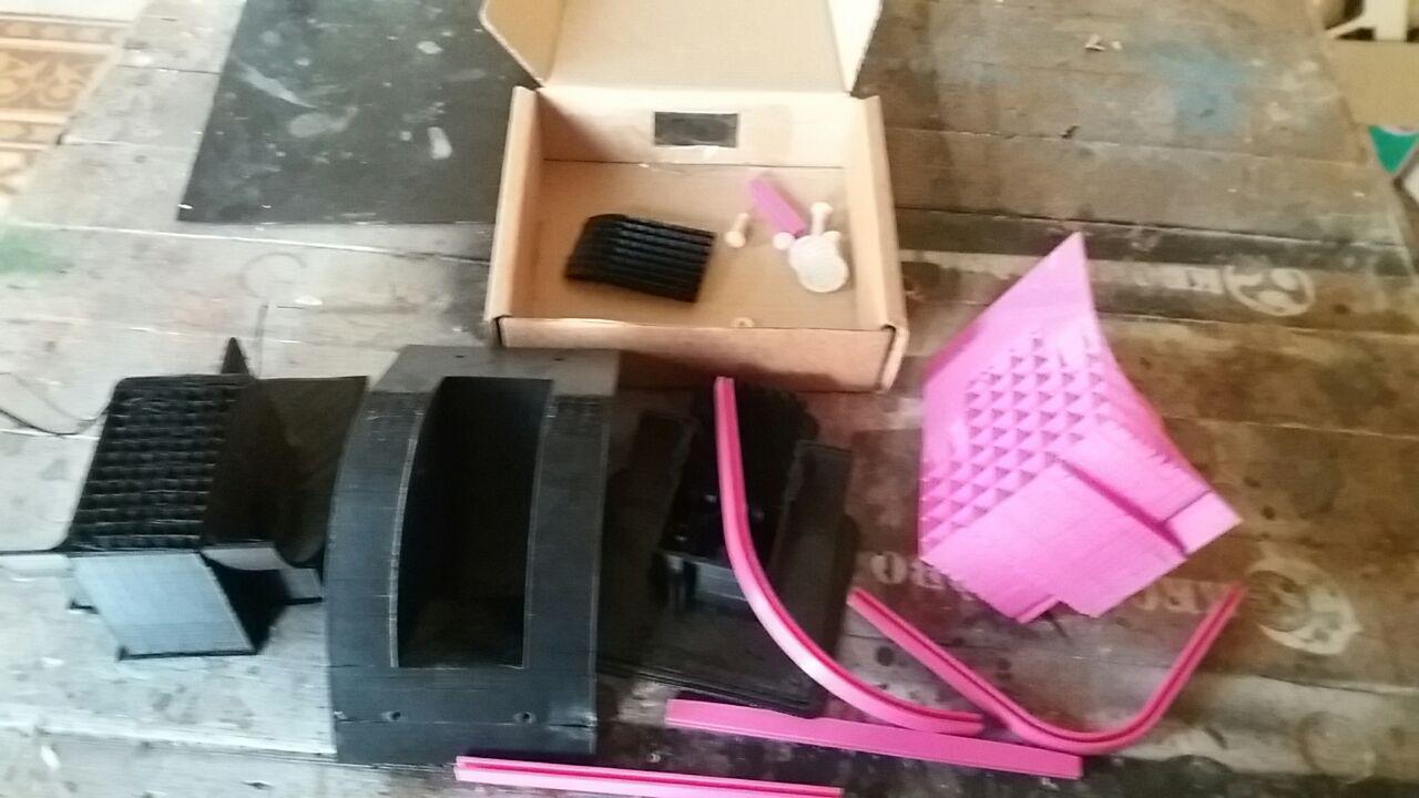
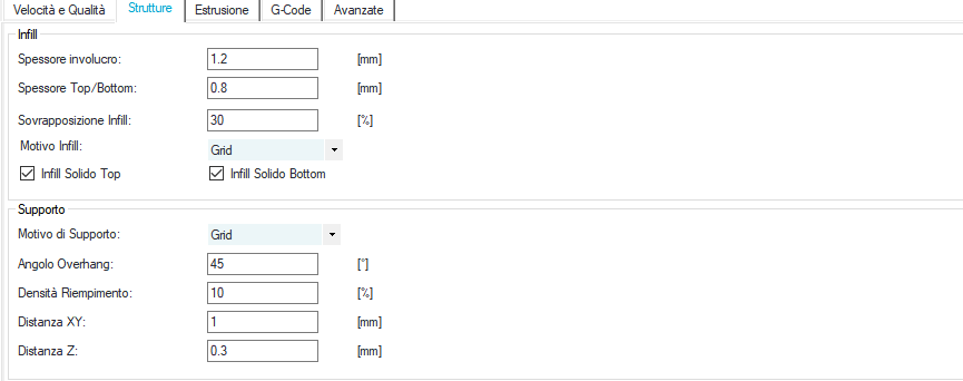
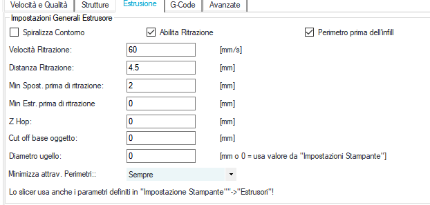
To print these components I used Repetier as slicer with the settings that you can see in the images below:
Speed and quality

Infill
Raft

Extrusion
Dynamo & gears movement
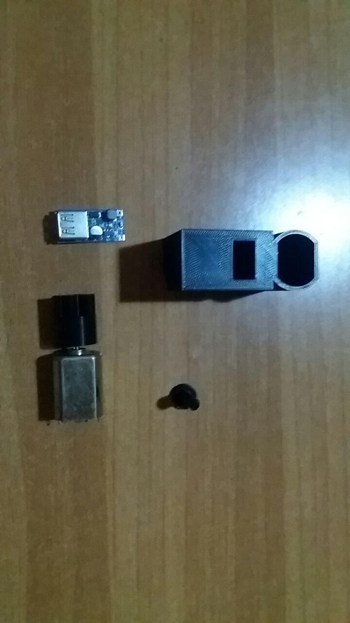
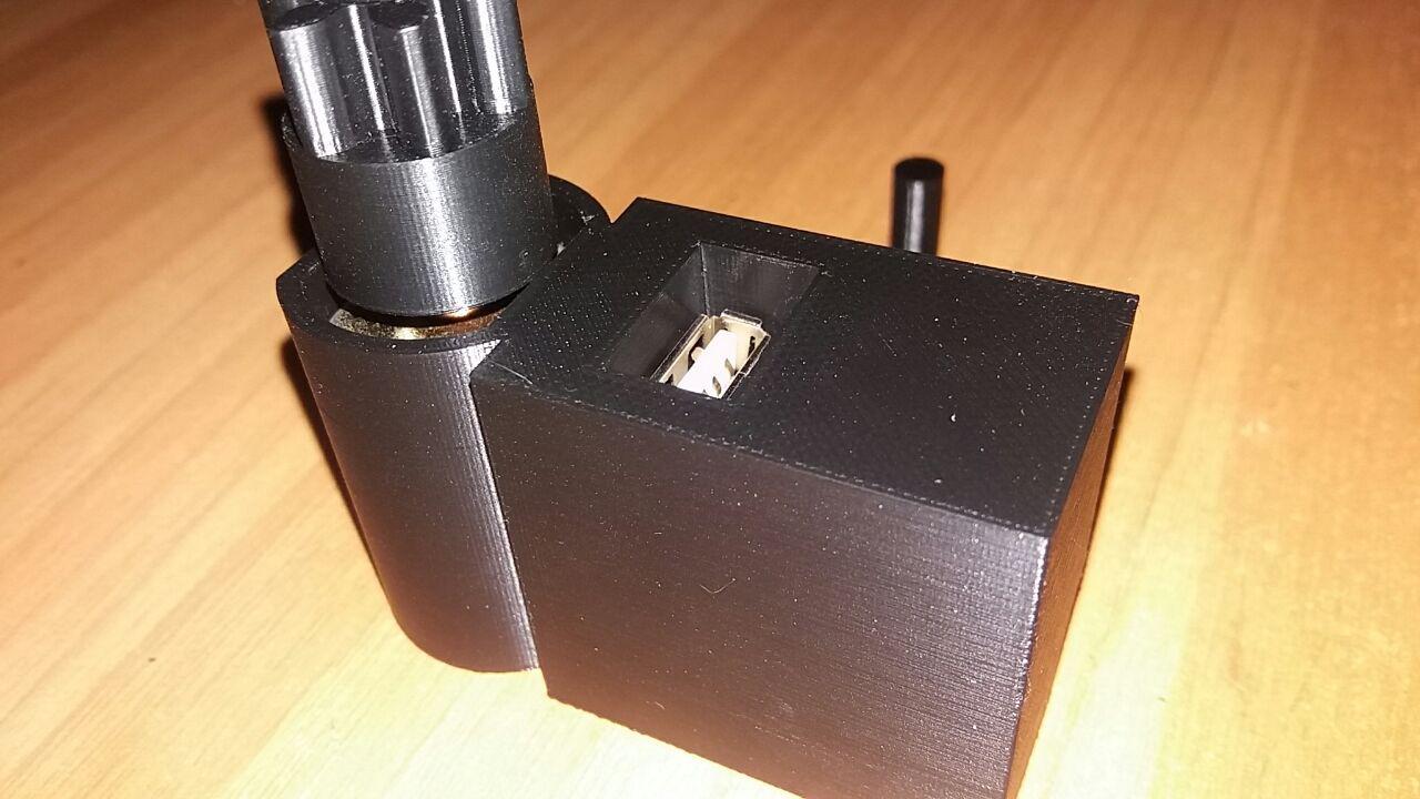
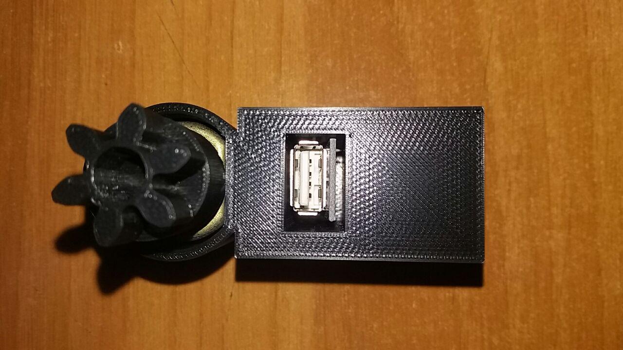
In this way I realized the dynamo that will charge the battery. I inserted the motor and the step-up module into the container I printed. On the 2mm axis of the motor I mounted the 6dent gear wheel which will be connected to the rest of the gears already installed on the trolley frame
Download ZONE
- 6 teeth axis
- 20 teeth axis
- Nut 20 teeth axis
- Handle ext
- Handle int
- Wheel1
- Wheel2
- Dynamo
- Inflator hook1
- Inflator hook2
- Wheel component1
- Wheel component2
- Wheel component3-4
- Gear 6teeth
- Frame connector Dx
- Frame connector Sx
2D Design & Laser Cutting
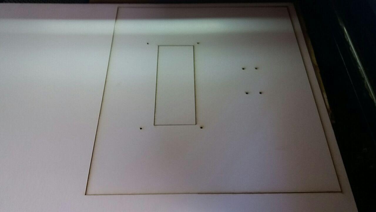
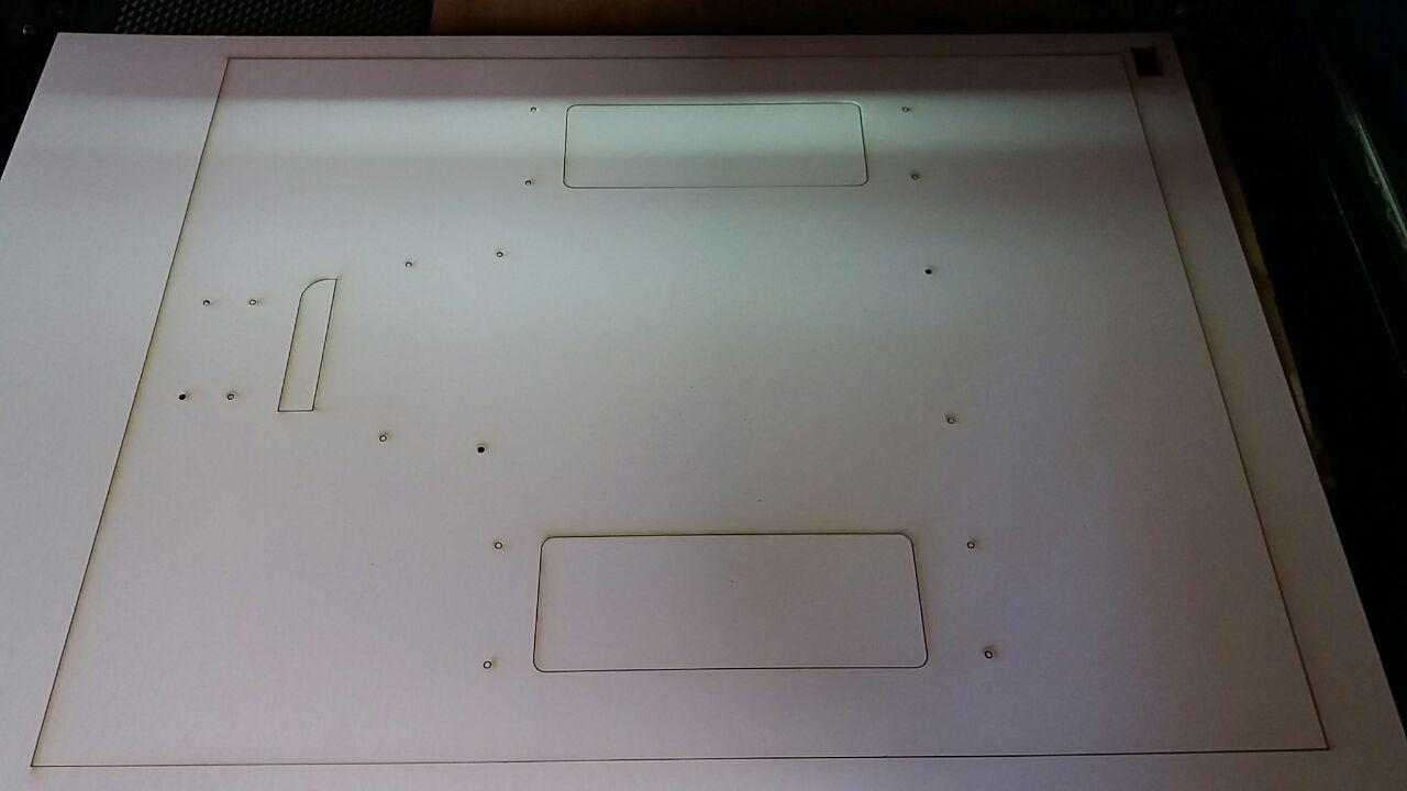
After unfolding my frame with Fusion 360 I created the sketch which I then exported as a dxf file
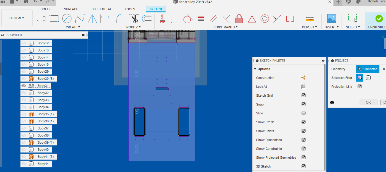
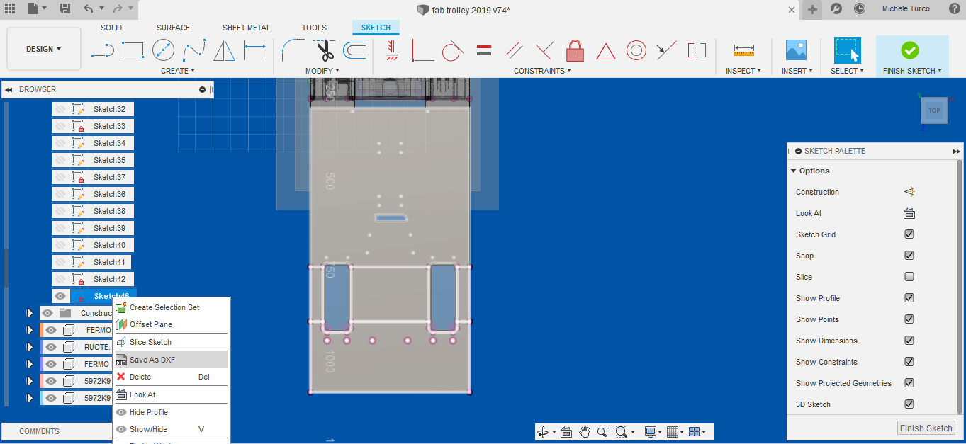
At this point I imported my file into the RDWORKS software (in the computer controlled cutting assignment I explain how to use it at its best)
I divided the frame into two parts because the laser I used (700x500mm) is smaller.
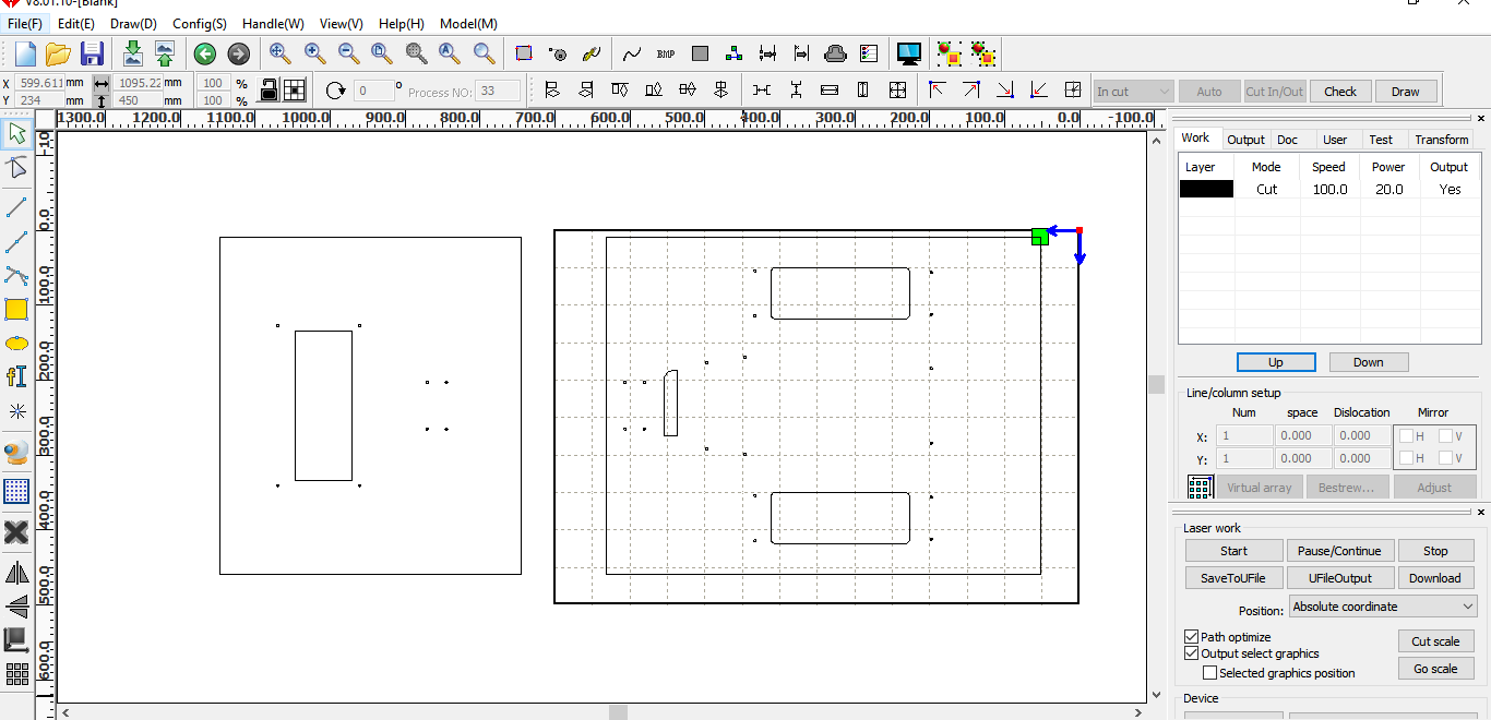
This is not a problem because I will assemble the two parts with an adhesive band
These are the settings I used for cutting the 2mm cardboard
- Speed: 100mm/s
- Power:20%
- Frequency:50Khz
So I got the pieces of my frame
Download ZONE
Putting all together
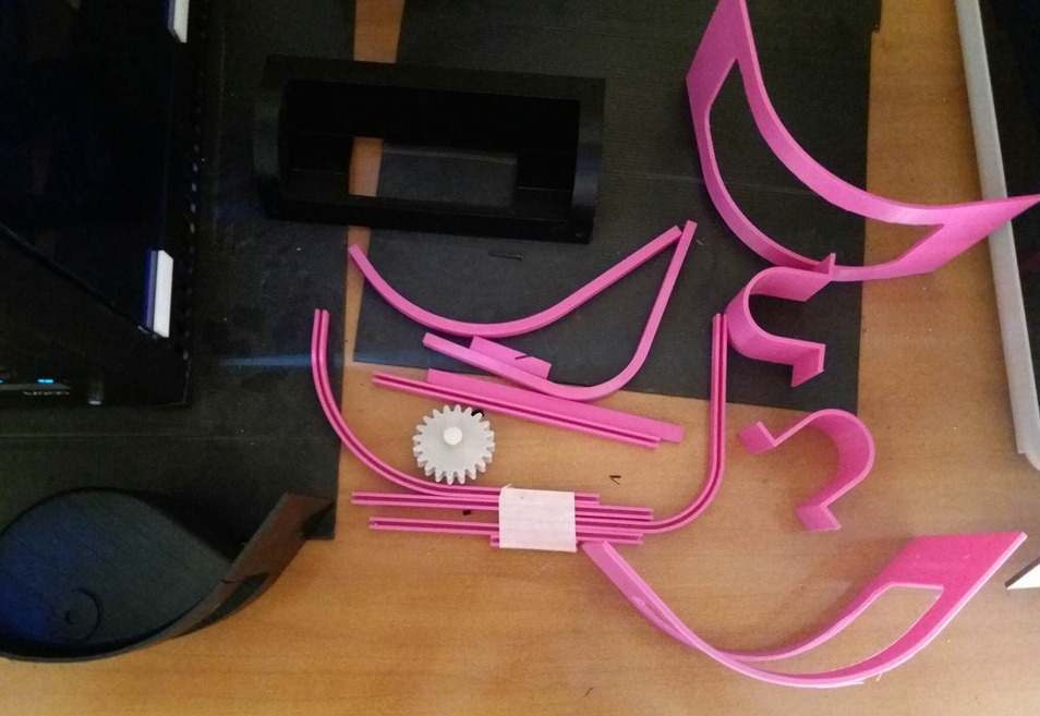
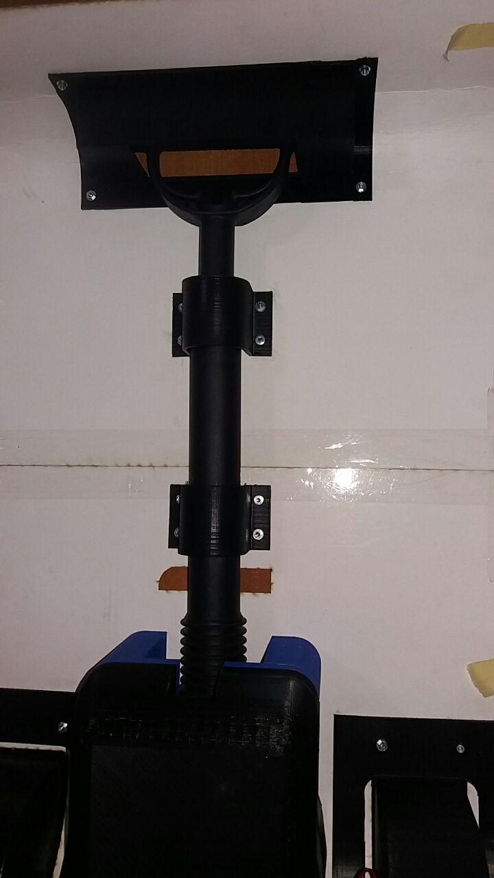
After assembling the frame with the wheels, wheel covers and gears, I position the dynamo with the necessary connections. Test of the movement of the wheel that powers the dynamo
I then did a test of the fluidity of the trolley movement during normal use, that is, walking. I therefore made sure that all the gears moved regularly, the walk was fluid, and the handle was rigid and resistant
In the end I tested the opening and closing system of the handle and the air bed
Download ZONE - CAD FILES
Presentation

This work is licensed under a Creative Commons Attribution-NonCommercial-NoDerivatives 4.0 International License.
- Back To: Home
- Date: June
- Service: Final Project
