Computer-Controlled Cutting
Assignment:
Group Assignment: make lasercutter test part(s), varying cutting settings and slot dimensions
Individual Assignment: cut something on the vinylcutter design, make, and document a parametric press-fit construction kit, accounting for the lasercutter kerf, which can be assembled in multiple ways
Work
This is for me, one of the important machine I want to learn for my future. Before all my work I need to kwon how Epilog Helix Laser Cutter works, and his most important funcion; Pros and Cons of laser cutting. For the First the laser must be prepared before send the file and start to cut whatever we want.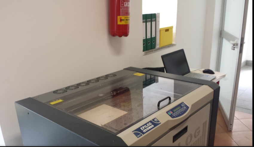
I use the both Default Epilog software used for laser cutting; and Visicut Software. Visicut is an open source software, and it can be downloaded at: this link
Visicut must be configured with the Epilog Helix Laser cut configurations; and what kind of material we want to cut(for the first Test we use cardbouard of 6mm) Visicut has this kind of user interface; and the mosts important parameters we must sets are: Frequency,the Power, and the Speed of the Laser. When we open Visicut we have this interface:
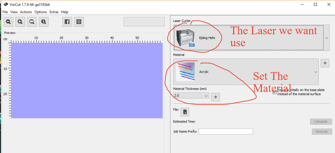
For the Firsts test I use cardboard, we set tollerance to zero; that means the thikness of the cardboard is 6mm, and we do a male and female joint with a hole of 6mm.
Test One: Power: 40 - Speed:30 - F: 500.
The cardbord was marked, but not cut. Test Thwo: Power: 60 - Speed:20 - F: 500.
The cardboard was more marked but Isn't yet cut.
You can see the the result on this picture:
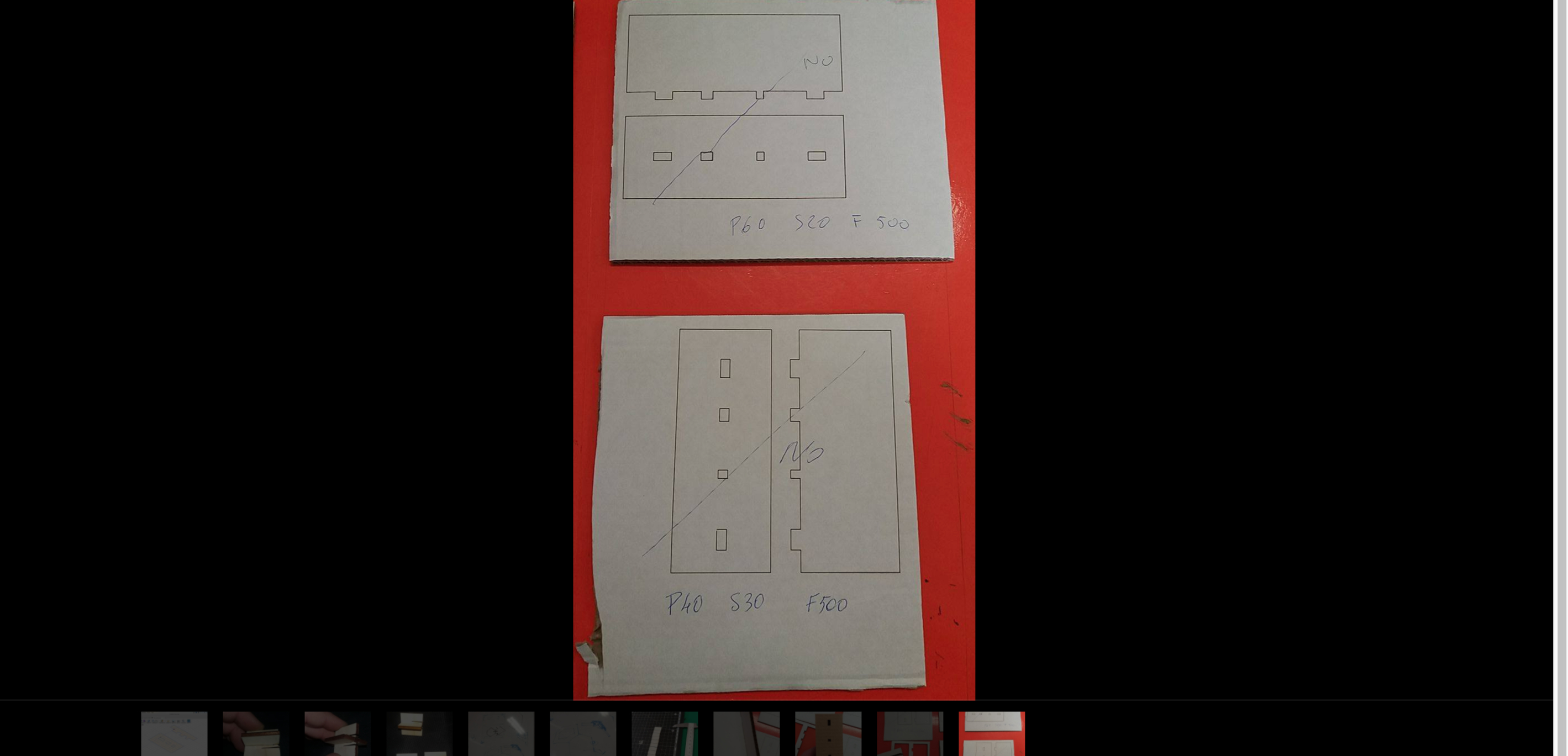
On the Test 3 : We Set Power: 100 - Speed:30 - F: 500.
And the cardboard isn't yet cut. The Last Test was successful with this Parameters: Power: 100 - Speed:15 - F: 500
You can see the result on this picture:
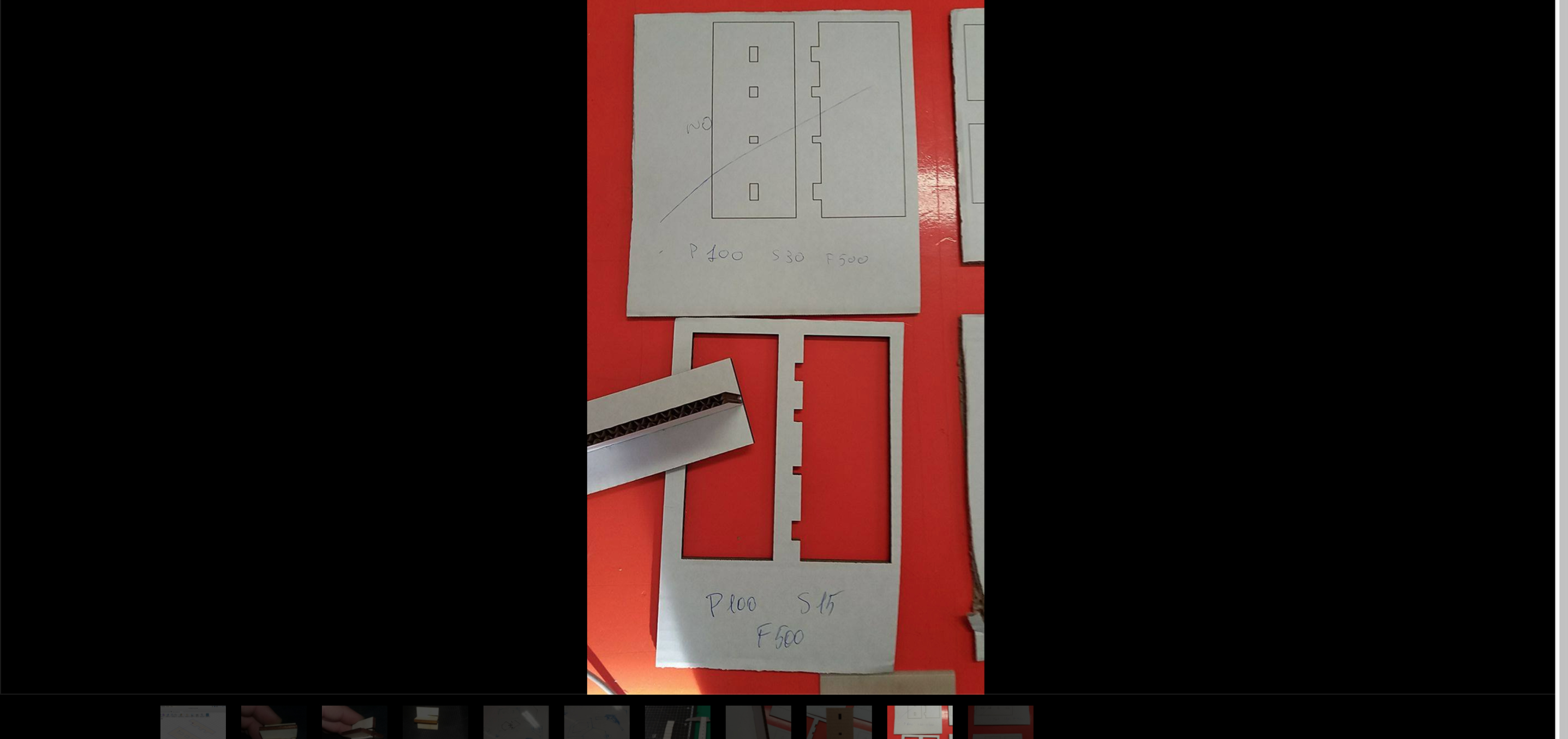

In the group assignment we calculate also the kerf value. We Cut 9 little piece of plywood for determine how the kerf is; and how is the perameter to considerate when we cut something. The follow link show how we calculate the Kerf: Group Assignment
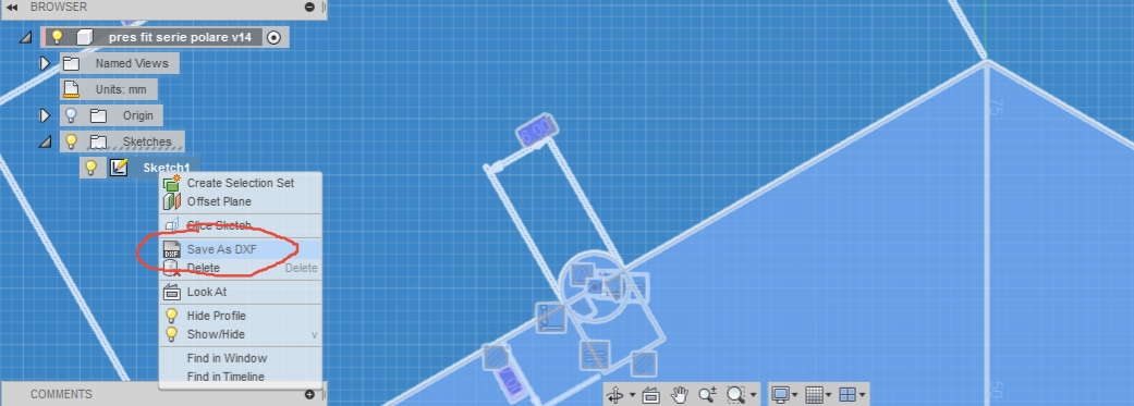
The Next Step For me, is to choose a Parametric software that can help me to redefine the parameters of my joint design every time i need; expecially for the joint of my snapfit presskit. The Software I Choose for my design is Fusion 360. This software is very powerful software, but It don't let me export my sketch in dxf or other file format useful for laser cutting. The file i need to generate, is a dxf extension. For this reason I found a plug-in for fusion 360, that able me to export every sketch i do, in a dxf file extension, in this way i can launch my file on the Epilog Laser. The plug in I installed on my Fusion 360 is this:
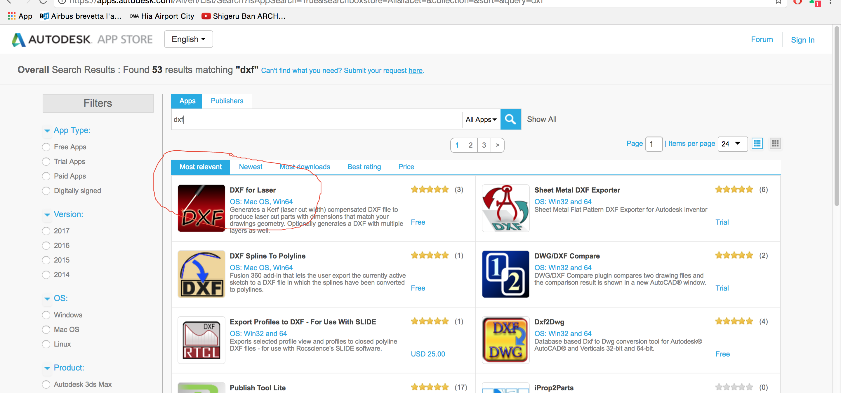
and you can find it at this address on Autodesk App Store For the Group Assignment we do different kind of test, we start to design the joint with a parametric software; The First Test of Joint is This:
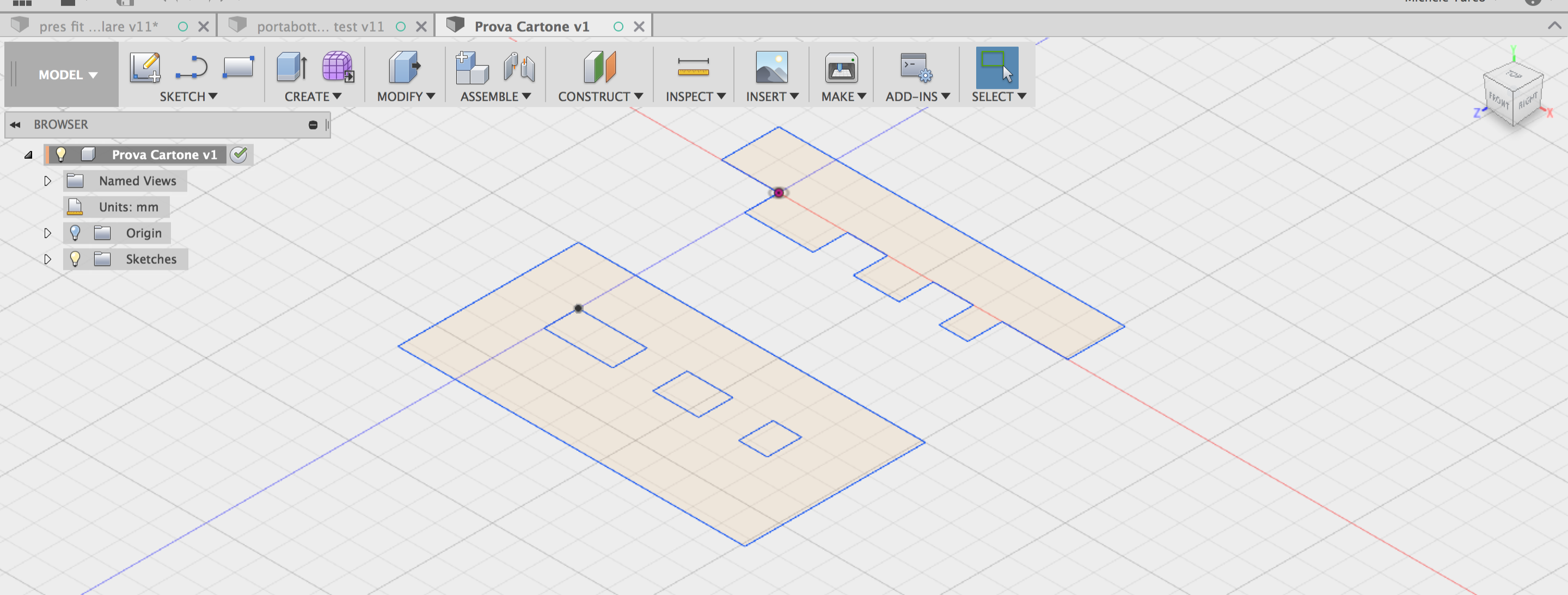
and after we cut it in cardboard with laser. You Can See the different measures we set to the joint. We do also different kind of test, for testing the Power, The frequency and the Speed of the Laser.
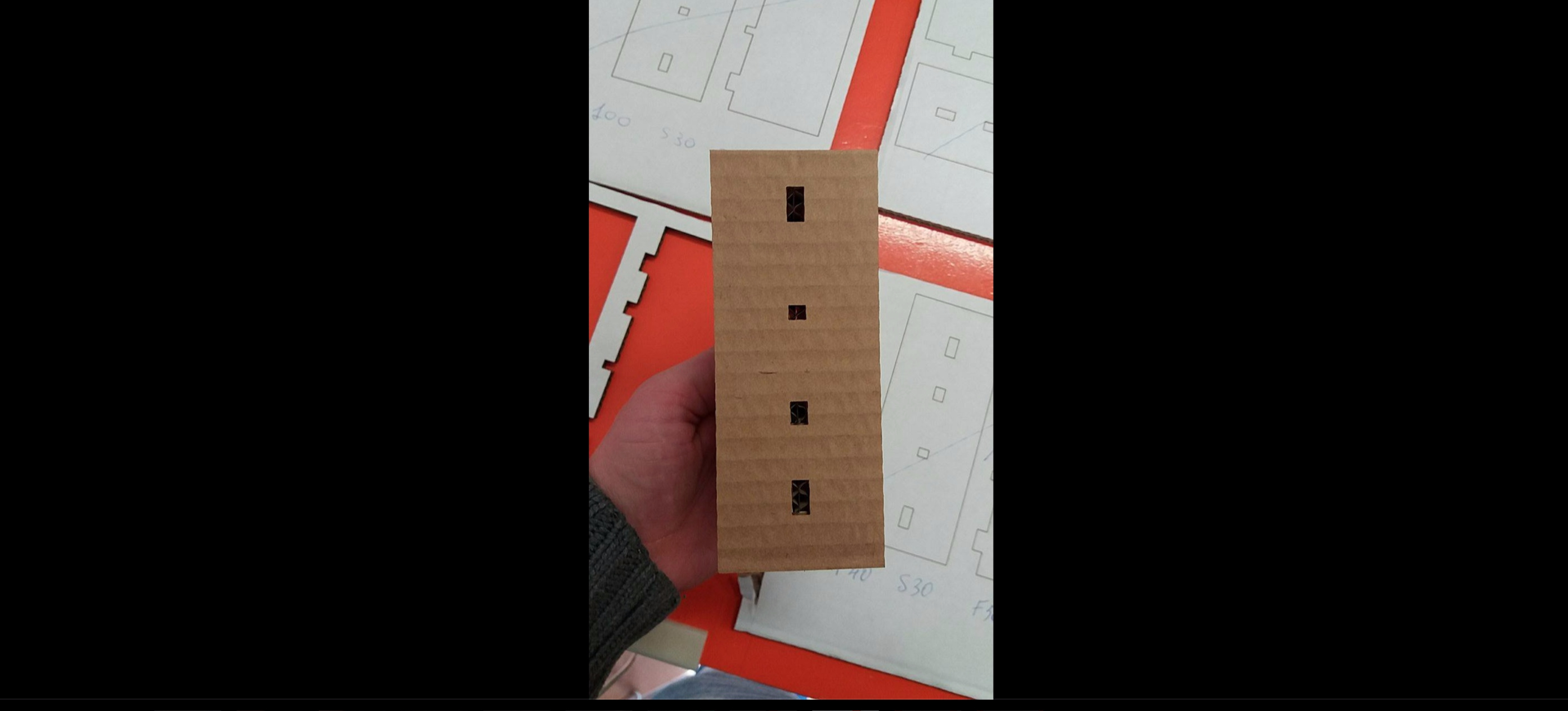
Also we make this Joint with plywood: More information about group assignment at this link
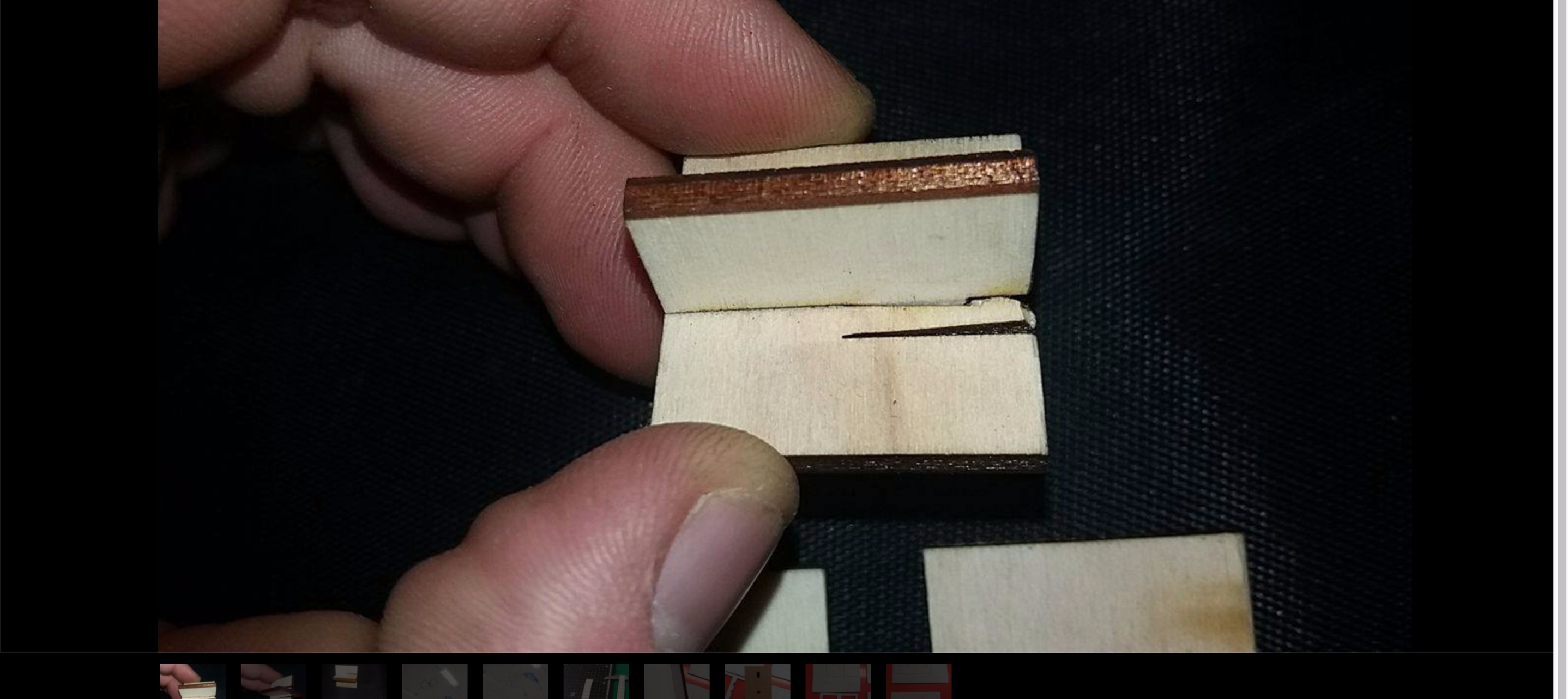
This is a very useful Joint, and you can find other like this at this Address Also on This link
Press Fit Construction Kit:
The concept:
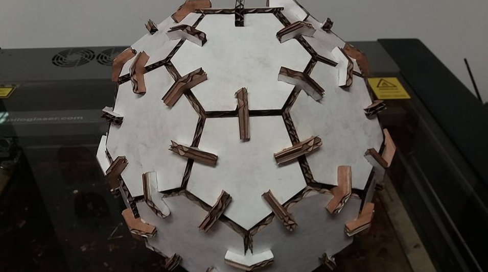
For my press Fit Construction Kit I decide to make an Truncated Icosahedron or simply called :Football Ball. For This Solid I do different researches, fot understand how i can contruct the trunched icosahedron once finished to cut the cardboard. I found some important informations on this website: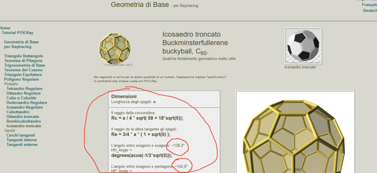
I must use 2 different joint, because betweek the hexagon and hexagon there's an angle of 138,2° and between pentagon and hexagon there's an angle of 142,6°.
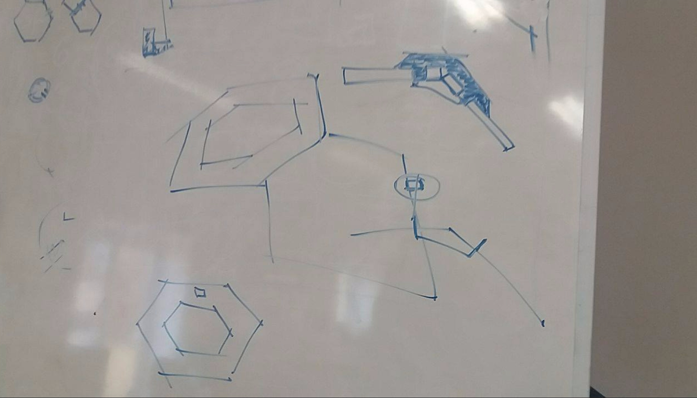

The Design:
For the truncated icosahedron I use Fusion 360 , and I krow that I need of 12 pentagon and 20 hexagon, and I need to do two kind of joint: one with an angle of 138,2° and another with an angle of 142,6°. In Nature we can find this geometry also in this mushroom: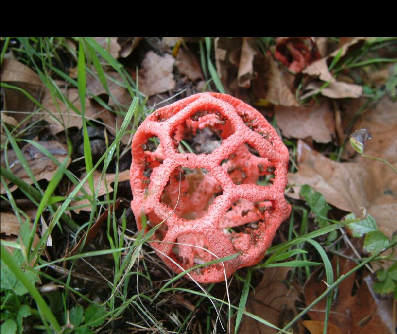
This Is my design and the two joint:
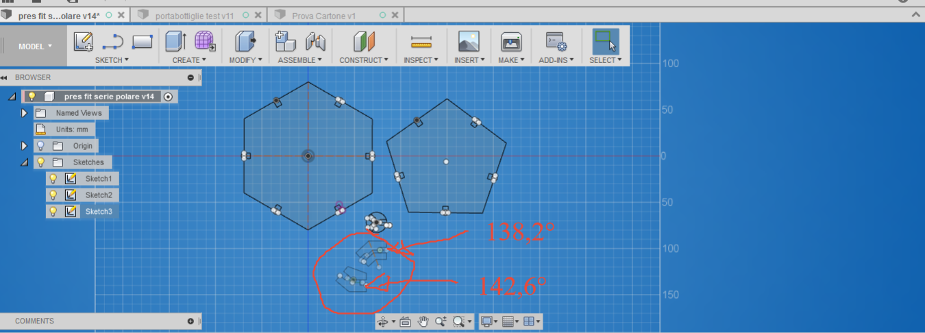
Also in this case the tollerance is egual to zero. I realize a parametric Design usign the contraits of Fusion 360, and If I need to increase the tollerance for the thikness of the cardboard, I only modify a parameter i need and the rest of design fits all it's form.
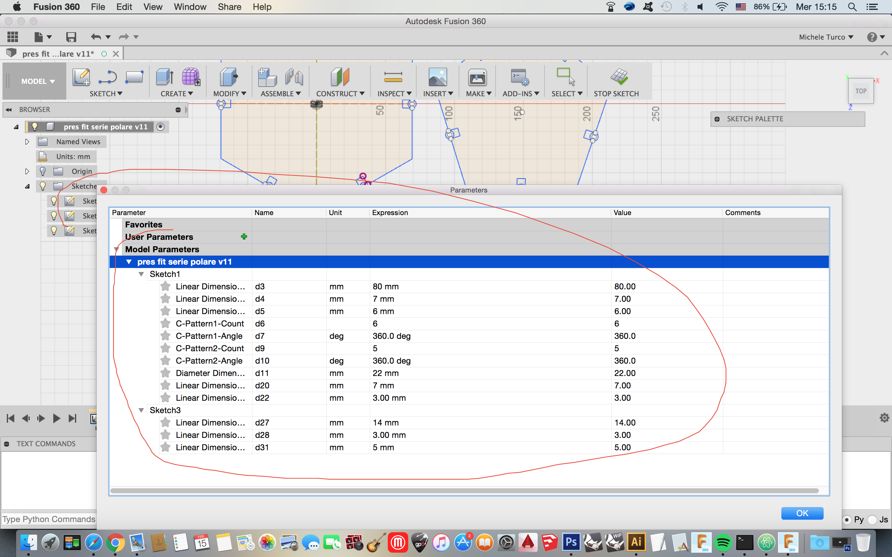
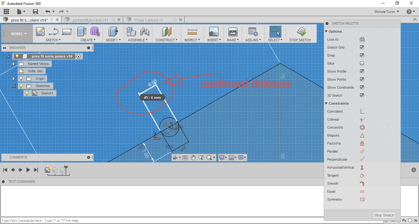
At the End I export the sketch of my project in dxf format in this way:
This is my Pressfit construction Kit:
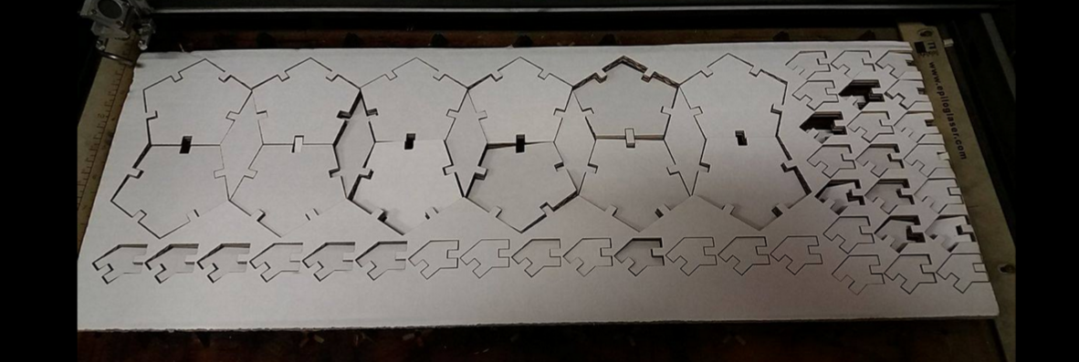
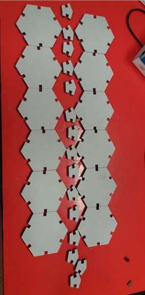
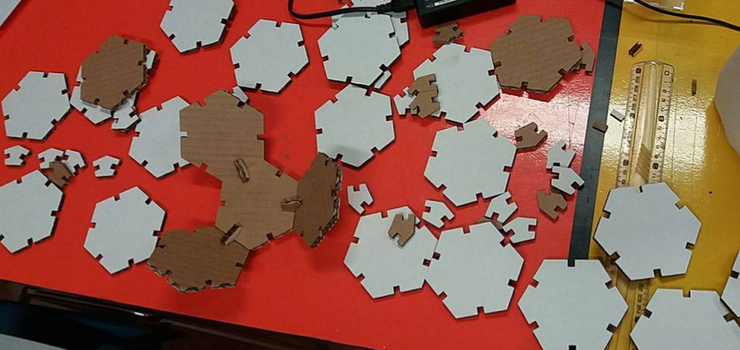
And this is the result once assembled :
Download the File:
Truncated Hexagon:
The Neapolitan Amulet:
I try to use also 123Dmake, it's a very useful program for laser cutting. and i create a famous neapolitan amulet with Rhinoceros.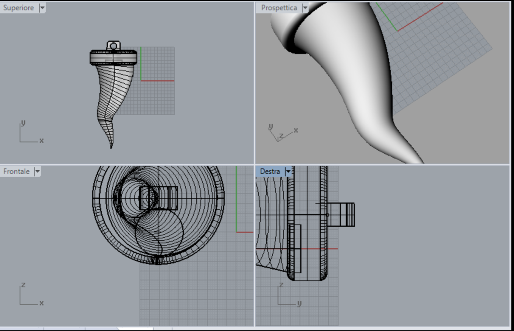
after I import this deign in 123Dmake for create the plan.
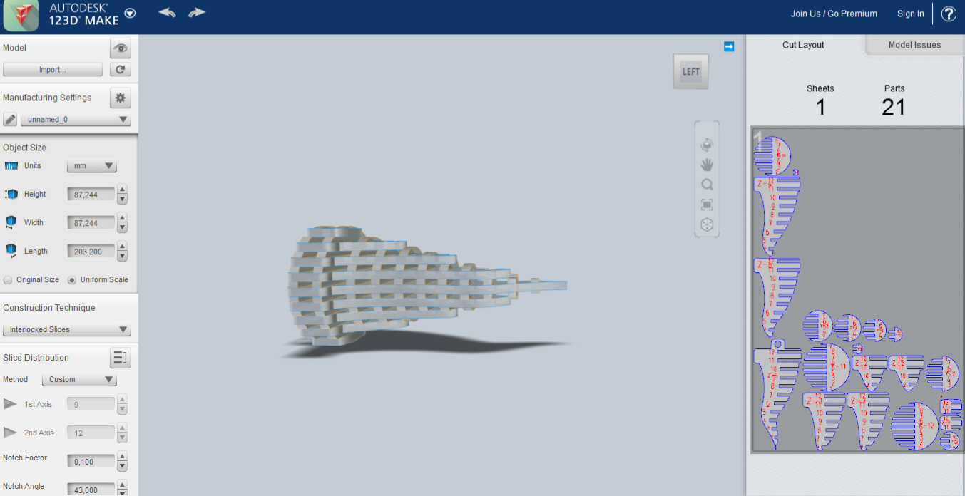
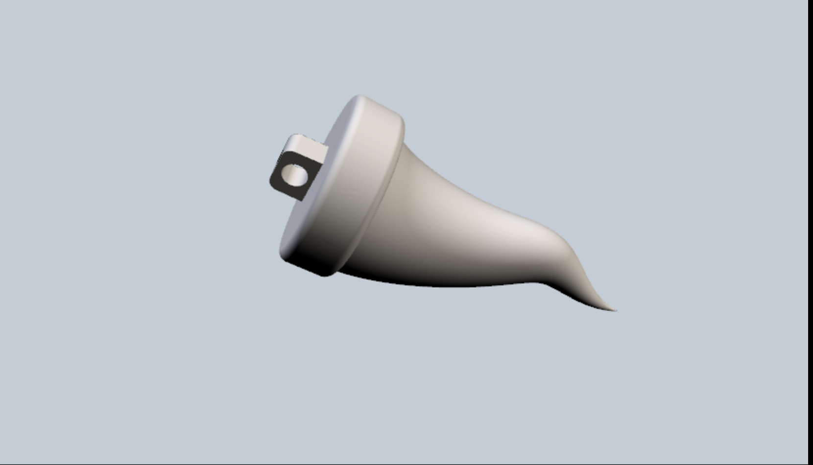
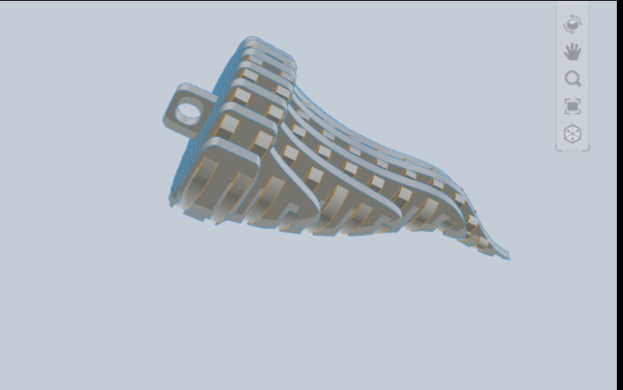
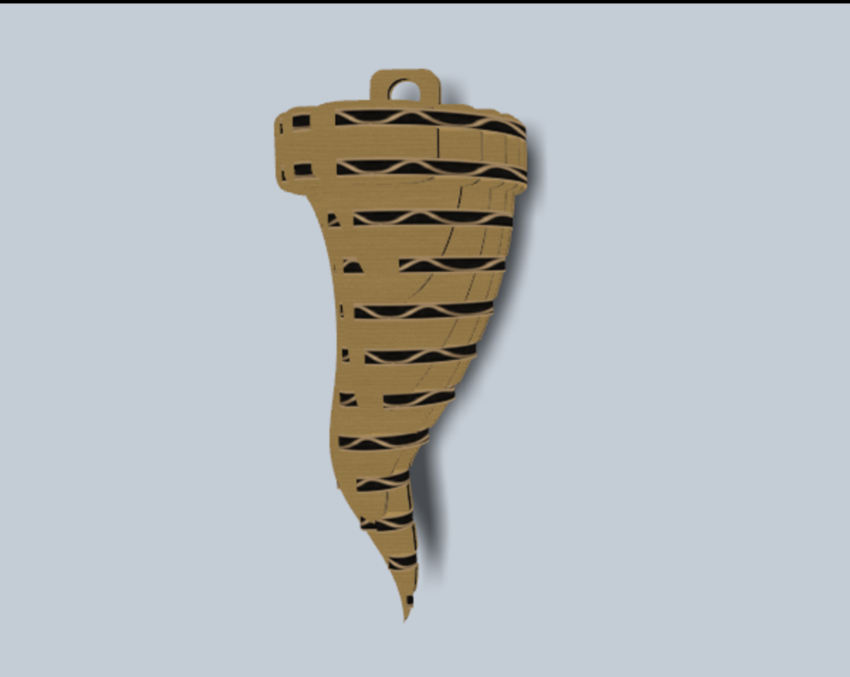
This the File of My Neapolitan Amulet
Bottle Holder
For Laser cuttig plywood i choose to design a bottle holder. Also in this case i choose to design it with fusion 360, and we use a plyeood with 3mm of thikness: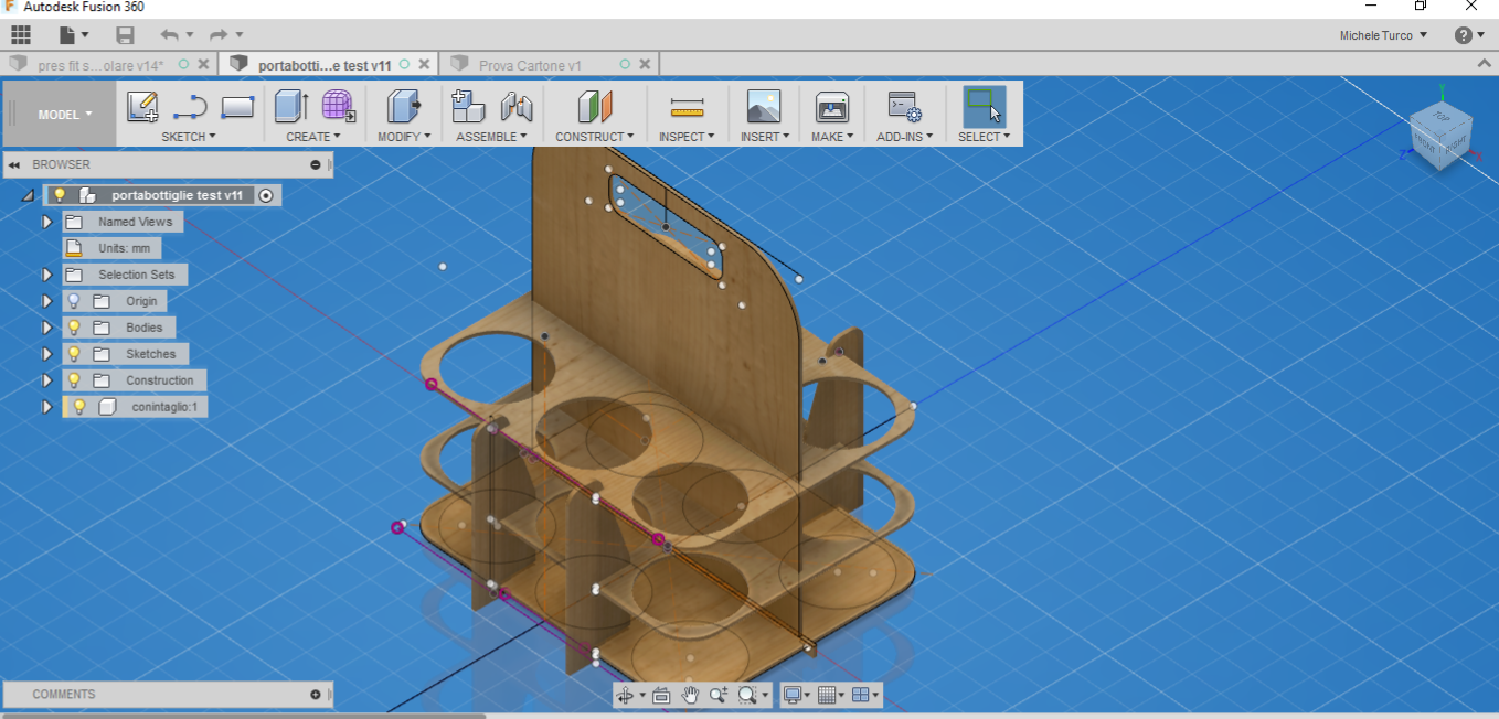
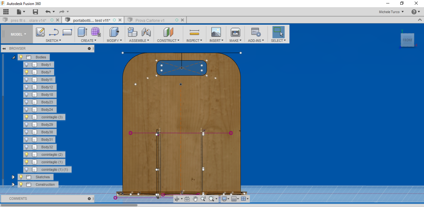
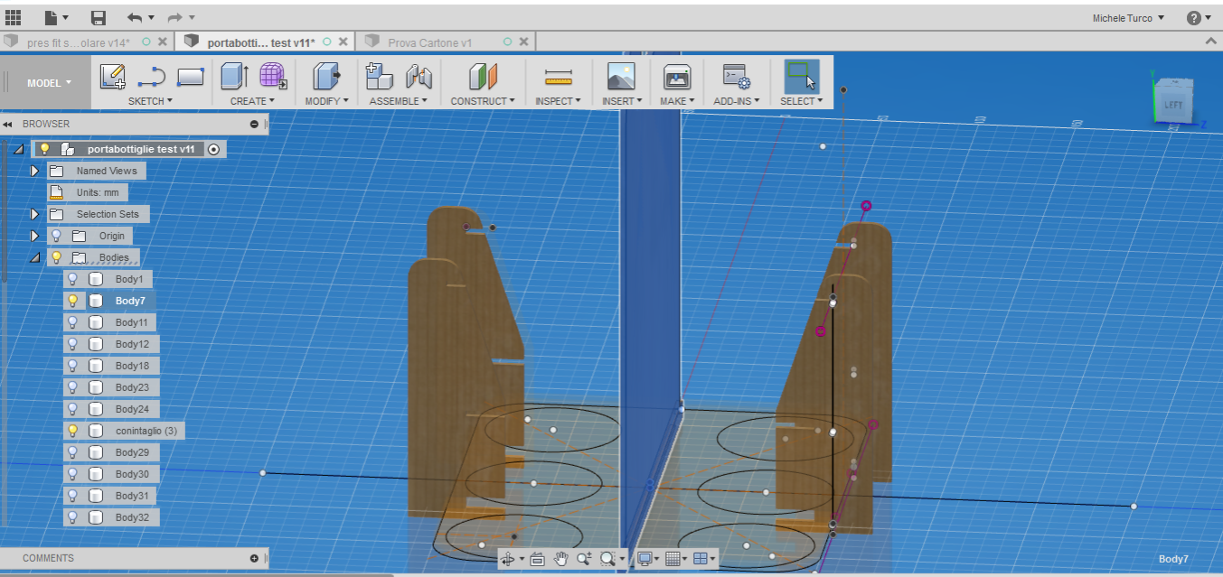
Downlad the File: Bottle Holder
Cut Something with Vinyl Cutter:
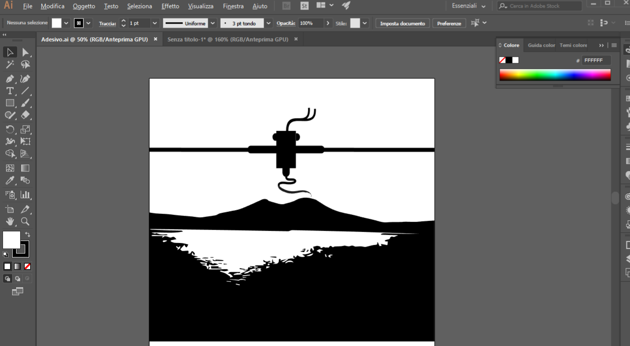
For the assignment with the vinyl cutter I decide to create an image with Adobe Illustrator and try to use Fab Moduls for generate a dot.cam file for the vinyl cutter. In Illustrator I use this image for create the vector.
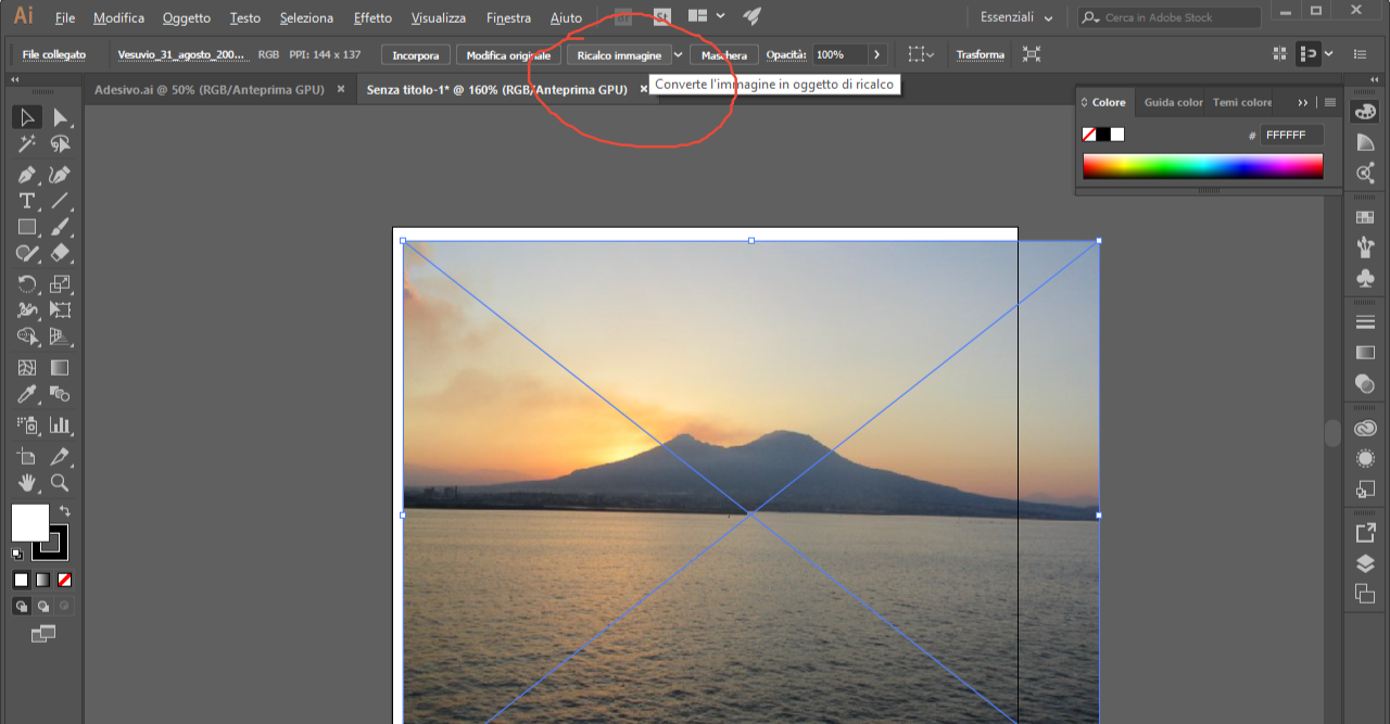
This is the image I generate, and I modify it creating a big extruder on the top of the picture.
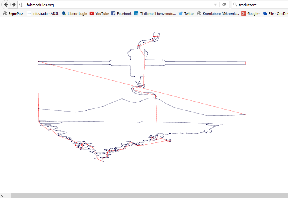
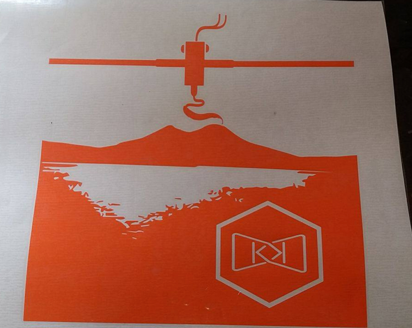
Download the File: Vesuvius Extruder
New Experiences
I have the desire to integrate this assignment with the following experiences: Before doing this, I indicate some references for the laser machine I used :- Laser cutting and engraving
- Power 80W
- Cutting Area: 700 x 500 mm
- Materials: wood, cardboard, PMMA, textiles, etc.
- Supported files: DXF, AI, EPS, JPG, BMP
Air Balloon
For this exercise I used the following software:
- Fusion 360
- Slicer for Fusion 360
And the following materials:
- 1 sheet of plywood 700x500x4mm
- Spray paint of different colors
- String
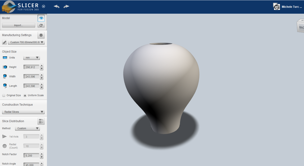
The imported file will appear like this:
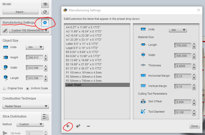
The second step will be to set the "Manufacturing settings", ie the parameters corresponding to the size of the sheets used, their thickness, the diameter of the tool used, and the unit of measurement used, in my case, in mm
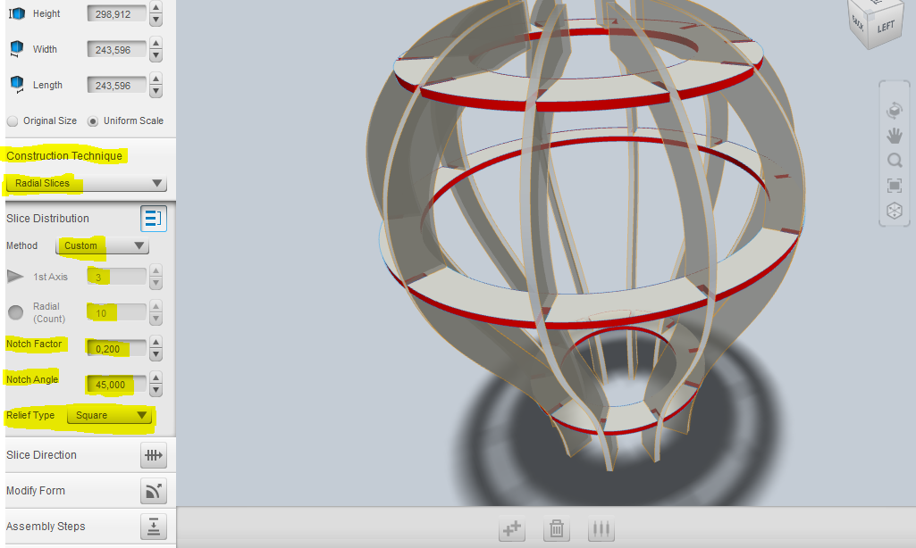
the technique I will use will be "radial slices" going to set how many slats will have to be along the Z axis (in my case 3) and how many radial slats (in my case 10). After that, the balloon will appear this way:
Another important parameter to set, will be the "Notch factor" which means this:
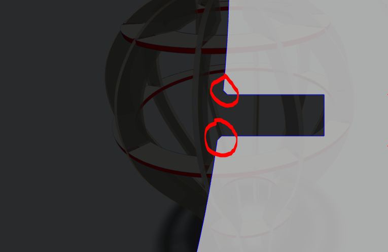
This means having the possibility of smoothing the corners of the joint in order to facilitate assembly. it is also possible to decide the bevel angle, its length and the type (in my case square)
Once this is done, I can export the sheets using the "get plans" button. The list of sheets generated by the program will appear. At this point we can decide whether to send the file to the fusion cloud (Fusion Team); or download files locally on your computer. you can choose between the dxf format (the one chosen), eps, pdf.
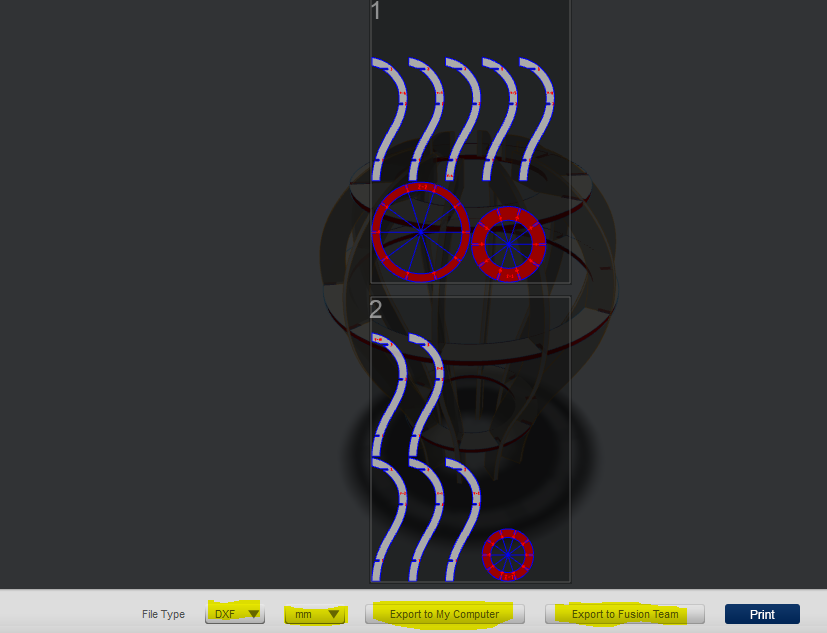
Important note !!!
The previous software (123D Make) had a very important option, not present in this softare: Nesting; very useful function, especially when you need to perform fast machining. Although in the previous version the Nesting function was not always efficient, it was certainly a very convenient feature to have.To create the lower part of the balloon (the passenger basket) I used (in this case) a very useful program to create simple boxes in a fast and effective way quickly and effectively, its name is "Boxes.py", you can find it at this url
Download Files
Here you can download the hot air balloon files and sheetsMachine settings and cutting
The software I used for cutting, is RDWorks. you can find more information and download the program at this link I indicate below, a brief tutorial for using RdWorks at this link After having nested all the parts, I get the whole balloon in a single 700x500mm sheet. This is the screen that shows up by importing the file.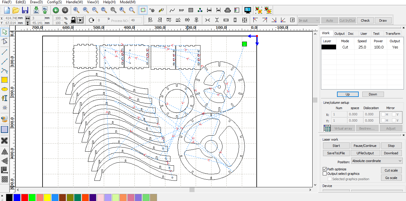
RdWorks like many other Cam software, uses as file format dxf, Ai, svg, etc. In my case I prefer to use the ".Ai" extension As you can see in the image, I chose the black layer as the cut layer. Having a good experience on this machine, I have tested different types of material and different thicknesses. For this 4mm plywood I use the following settings: S: 25mm/s P: 100% F: 20Khz
This is the final result:
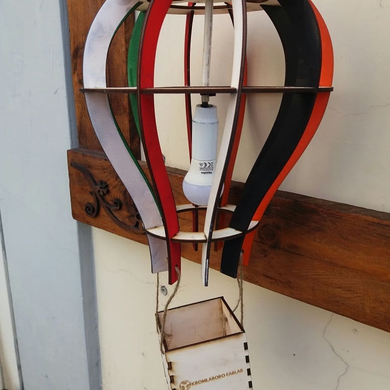
Tony Press Fit Construction Kit
I decided to create this kit because I had the desire for a kit that was inspired by the character of a dear friend of mine who passed away a few years ago, his name was Tony. At the same time I would like to create a fun contruction kit to build, and that is able to generate various figures. To create the concept I used Rhinoceros, to create symbolic objects, ie the bowler, mustache, umbrella etc. To understand even better, look at this link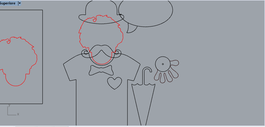
After creating the concept, I used Fusion 360 to create this kit, making the most of the potential of this parametric software. I imported the dxf file into fusion 360 and I will try out the constraits in the sketches. With the costraits it is possible to constrain the dimensions and the geometries of our design to specific parameters that we will choose. In my case the most important parameters will be the size of the joints; these must be able to be modified in order to have a perfect icastro according to the choice of the material used.
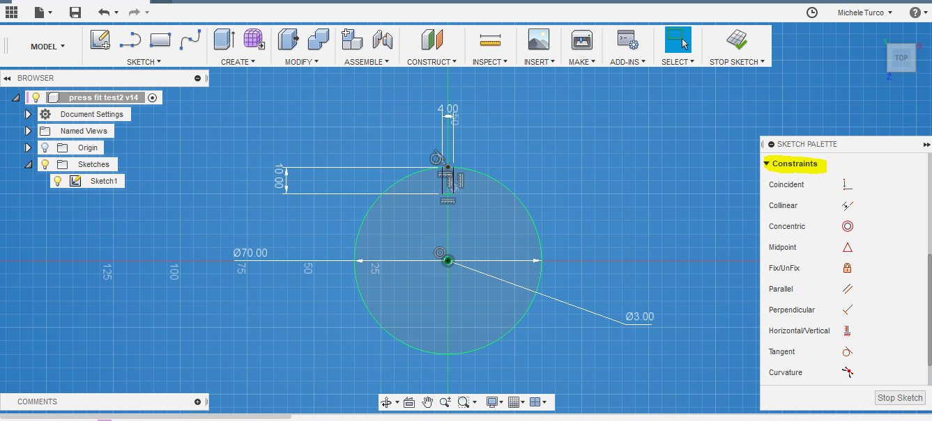
This is the link where to find the file created with fusion360 shared on the Fusion team cloud
TpressFit
Important note !!!
For my personal experience with Fusion 360 I noticed that this software manages the parameters better and re-computation of them with 3D geometries instead of 2D ones. Consequently, if too many contraits are used within a single sketch, even if geometrically correct, there is the problem of slowing down the softare itself, and also causing it to crash. All this does not happen by managing 3D geometries, even if constrained by parameters. Another important peculiarity of Fusion 360, is that of being able to reset the various features of sketches and 3D objects, going back to the history of construction at the bottom.
Or even easier, access the parameter table and change the ones you want
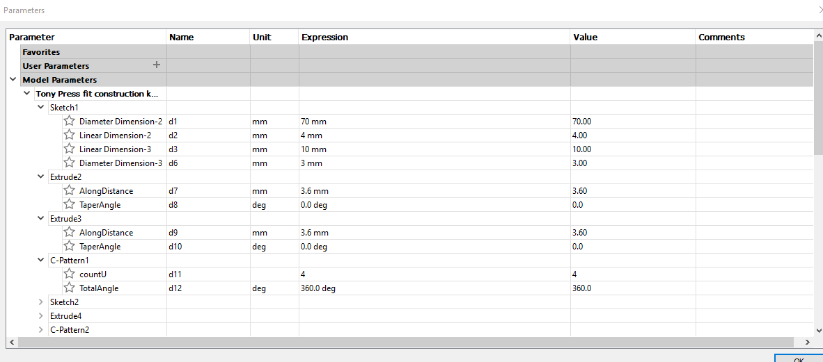
Download the files:
Here you can download the sheets filesMachine settings and cutting
Also in this case I used RD Works and 4mm plywood sheets, with the same parameters used previously for the cut; that means: S: 25mm / s P: 100% F: 20KhzIn this process I also included the engrave of a writing; I used the red layer to indicate the engrave, with these parameters:
S: 300mm/s P: 14% F:50Khz ScanMode: X_swing Interval:0.02mm
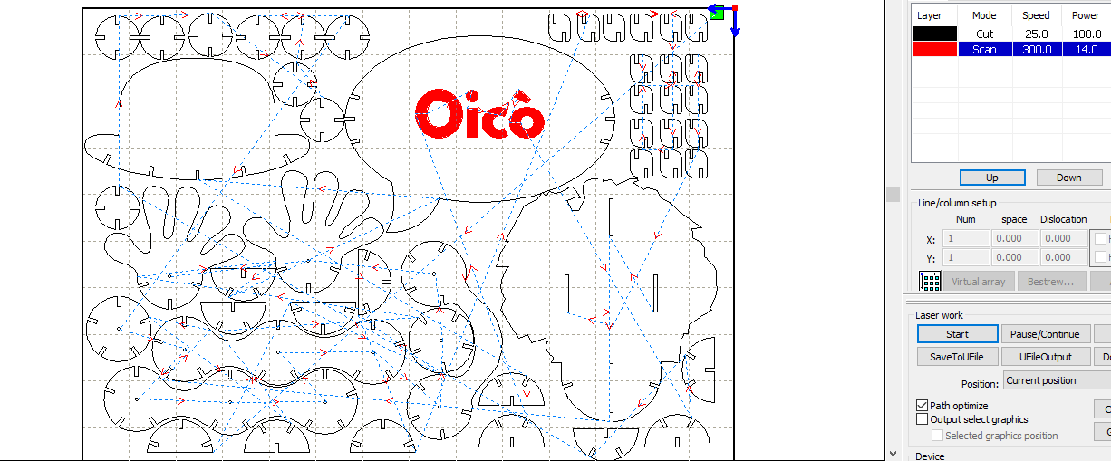
This is an image of the kit just cut, before being painted
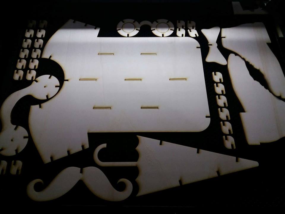
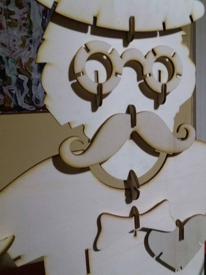
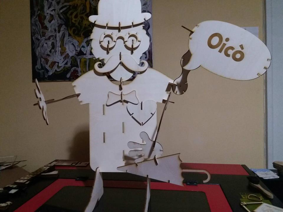
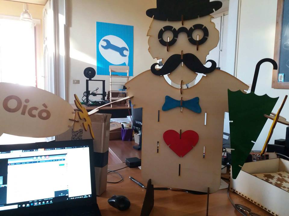
Here a small video of the processing this is a final shot of the mounted kit (one of the possible configurations)
Safety and precautions
The laser cutting machine is a very dangerous machine if used in the wrong way, so I recommend to always pay attention to its use. First of all it is always good to use protective glasses, because, even with the door closed, the light could damage our eyes.
It is always good to pay attention to having the machine door always closed, especially during processing, and make sure there are no parts obstructing the normal movement of the axes
Finally, it is always good to wear gloves to position and remove the panels to be cut, making sure you have good ventilation in the room where the work is carried out
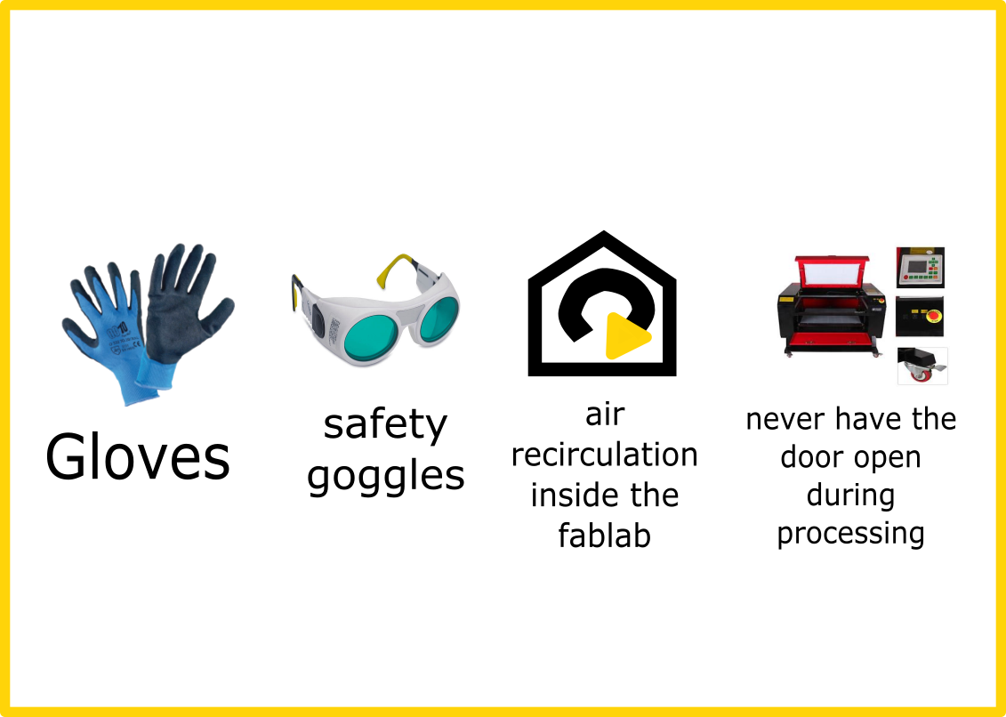
It is of fundamental importance to perform routine maintenance on the machines, making sure that the movement parts are always well lubricated. Do not cut prohibited materials such as vinyl, it can be very harmful !!!
Car Stickers
I wanted to repeat this assignment with my Brother Scunncut CM600 and create a car sticker using mirrored vinyl.

Before working on the machine, I prepared a file with Rhinoceros 3D with the dimensions I need. In my case the sticker will be applied to the back of the machine, and it will be 50cm wide by 9cm.
To make the work with the Brother Scunncut CM600 we need an adhesive pad on which the material we want to cut is placed (in my case vinyl). The mats that can be used with this machine are of different types, these vary depending on the degree of adhesion that the adhesive surface has, and then based on the size. There are two types of adhesive mats on the market: the first 300x300mm and the second 300x600mm; in my case I am in possession of the small one
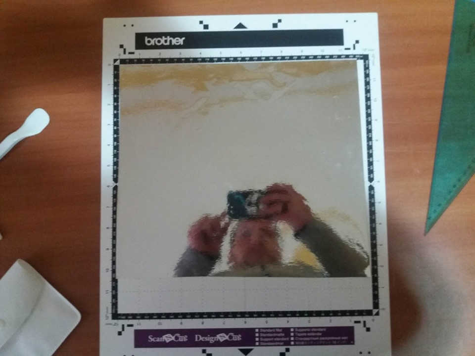
The brother makes available to his customers a cloud called CanvasWorkspace CanvasWorkspace where it is possible to download many ready-made files or where it is possible to keep those produced by us. The CM 600 has no wifi connection (unlike other CM series products), otherwise it would have been possible to send files to the machine directly from the cloud. In my case I need to upload the files to a USB stick which will then be connected to the machine. The brother scanncuts do not need settings for choosing the paths to be taken during the cut, these are generated automatically. Using the Canvas Worspace software the created file will be exported in the following ".fcm" format which is the native format of the machine. Through Canvas Worspace it is also possible to import files in ".svg" format created with other software. I personally exported the file from rhinoceros 3D directly into the ".svg" format and loaded it onto the USB stick; this will be read directly by the machine without this being converted into the native ".fcm" format
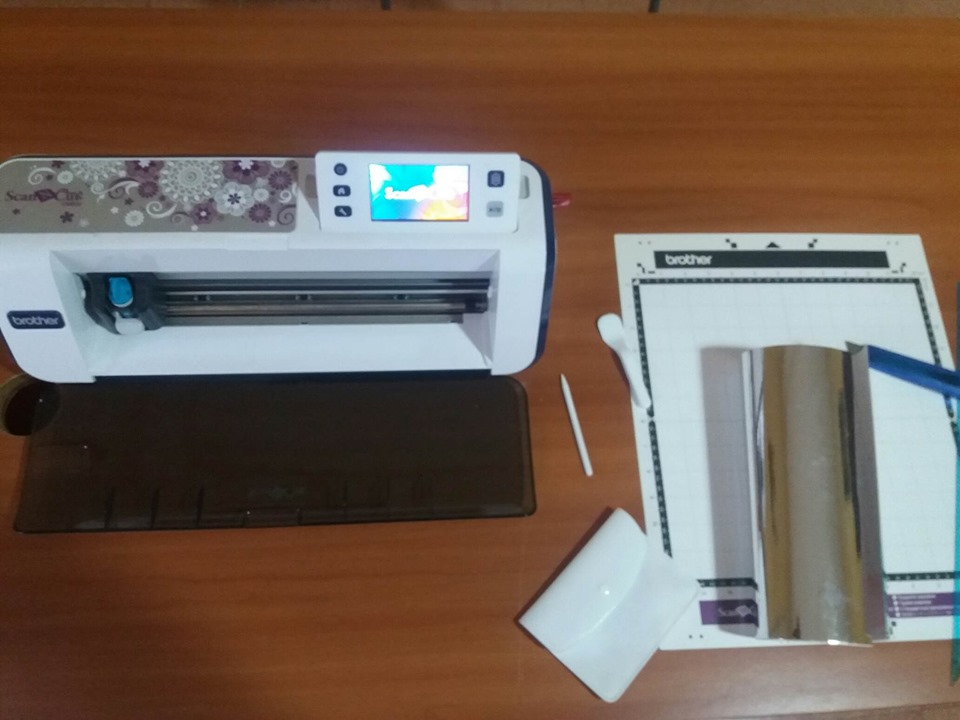
Machine Settings and manufacture
The most important settings to set are essentially two:
- Cutter extension
- Pressure applied during cutting operations
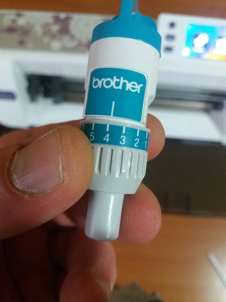
The cutter extension is set by first removing the cutter from its holder, and with both hands, rotate the cutter to the desired value. The brother helps us with a table, where the value to be set based on the thickness and hardness of the material we want to cut are indicated.
Below I indicate the links where you can download the Manual of the Brother CM600 and The table of settings for the most common materials
In my case, I'm going to cut vinyl from a thickness of 0.2mm so I'll have to set the cutter extension = 4 / pressure = 0
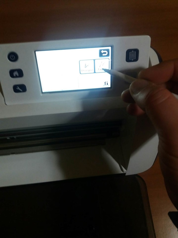
After setting everything I proceed to load the mat inside the support and I am going to start the processing Recall the file from the USB stick using the touch screen and at this point I am ready to start the processing by pressing the Start button
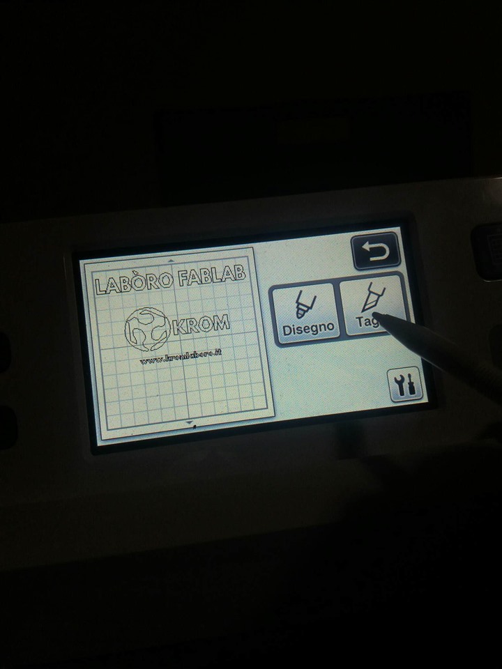
Below are some shots of the work
After cleaning the mat from all the excess parts, I used the transparent film to transfer the stickers to the surface where we want to apply it. I lined up all the writing I had broken down for space reasons and finally glued it all to the car. This the final result:
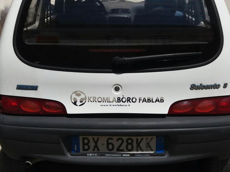
Safety and precautions
There are no special precautions for using this machine, I recommend wearing gloves when using tweezers to remove the stickers and the plastic spatula instead of the metal one
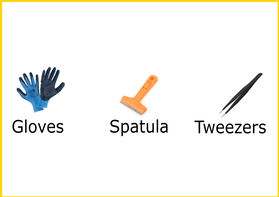
Important note: I advise you to pay attention to the removal of the blade, for any settings. The blade is very sharp, avoid going over the blade with your fingers
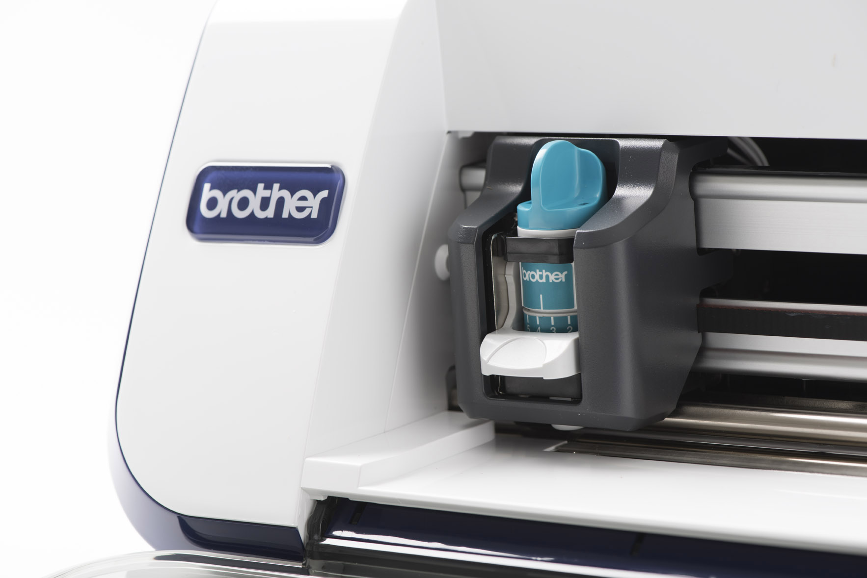
Download ZONE
- Truncated icosahedron
- Neapolitan amulet
- Bottle holder
- Vesuvius Extruder sticker
- Wooden Balloon
- Tony Press Fit
- Car Sticker
- Back to Home
- Date: February 2019
- Topic: Computer-Controlled Cutting