
Embedded Programming.
For the assignment of the 9th week: Embedded Programming, it will be divided into 5 parts: Datasheets, ISP connection, Languages and software, Group assignment and Download. The goal of this week is programming my hello world board.
Datasheets
In order to start programming, it is necessary to first know very well the microcontrollers that we are going to use and those that we have used in the past weeks, so we must read the Attiny microcontroller datasheet. The most used microcontrollers in the fabacademy are the attiny44 and the attiniy 45, another very used is the atmega328.Attiny44
The smallest microcontroller used in the Fabacademy, after having read the microcontroller datasheet, which you can see here, I observe that I only have 12 pins to be able to program: 2 Analog Inputs and 5 digital, PB3 and PB4 works as analog input and digital I/O but only one, never both at the same time. The PB0 and PB1 can use a pulse width modulator (PWM) internal to the microcontroller. In addition to a consumption of 300uA working at 1Mhz on your internal clock.Attiny45
It is a versatile microcontroller for simple applications given by the number of pins and its small memory: 4Kb of programmable memory.Reading the datasheet of the microcontroller here . This microcontroller has 2 timers internally for use without having a crystal oscillator, but on the other hand it still has a limited memory for programming: 4kB. For these cases it is recommended to perform a programming with a low level language to save memory. The consumption on the pins is similar that attiny44. It is observed unlike the previous model that we only have 6 programmable pins: 7 analog inputs (PA0 to PA7) and 11 digitals I/O, 4 of them use PWM (PA5, PA6, PA7 and PB2)
Below we can see an image with the pins of both microcontrollers.
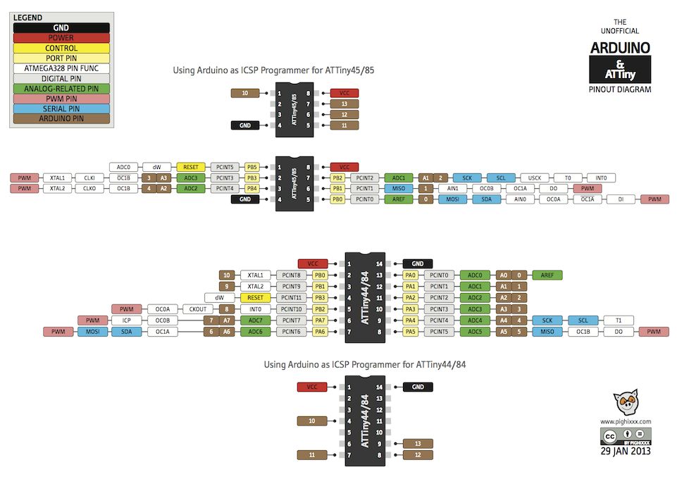
Source: https://www.instructables.com/id/Program-an-ATtiny44458485-with-Arduino/
Atmega328
The atmega328 is a much more powerful microcontroller than the previous one, not only for its memory: 32Kb flash, also for the number of programmable pins: 23. But its consumption is 0.2mA. You can see its datasheet here. Very apart from the HelloWorld plate, I tried to make a board on the base of the 328 atmega, for this I use a basic scheme as shown in the picture, but I change some components like the capacitors and oscilator: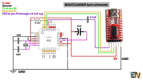
Source: http://www.electronoobs.com/arduino_tut6.php
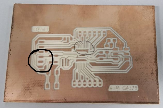
The final schematic design is the following: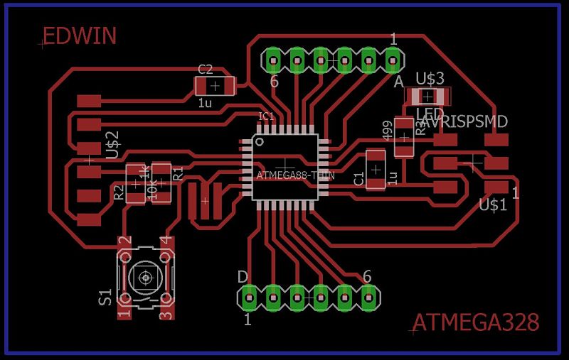 At the time of making the board, the milling cuts some of the tracks and loses continuity, so I continue with the programming of the helloworld and I will leave the atmega for later.
ISP connection
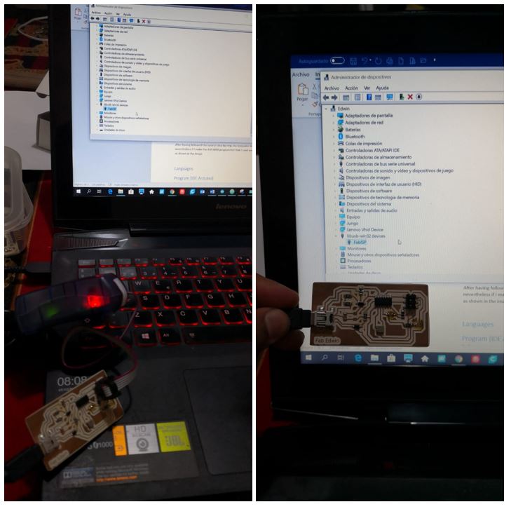
In order to program the board, I need my computer to recognize my ISP using Windows, in order to recognize the board I follow this tutorial. After having followed the tutorial step by step, my computer does not recognize the ISP.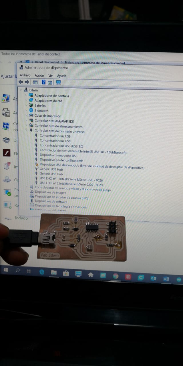 But nevertheless if I make the AVR MKII programmer that I used weeks ago, my laptop recognizes my ISP, after making this connection, I disconnect the AVR and it keeps the recognition of my ISP as shown in the picture.
 Once the ISP is recognized, programming could begin.
Languages and software
The microcontrollers use different programming languages such as the assambler, the c ++ and even some softwares use a modification of some programming languages, such as the one used by the Arduino hardware.IDE Arduino
A very recommendable software to program microcontrollers in a simple way and with hundreds of examples on the internet, is the Arduino IDE. It is a free and widely used hardware worldwide.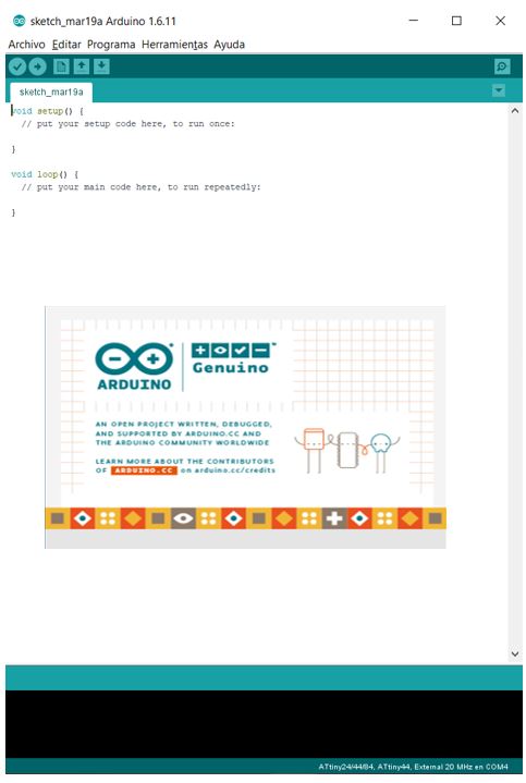 The software is free download, from this link which can be installed on both Windows, Mac and Linux. In my case I use windows.
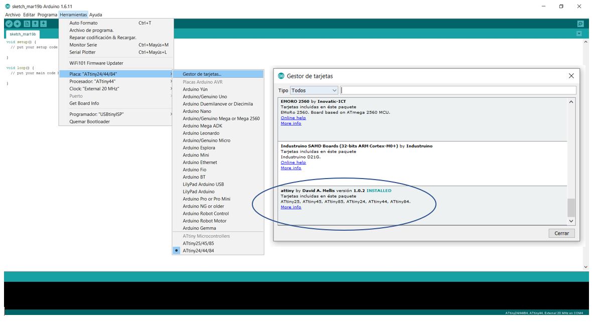
After installing the IDE, the first step is to install the necessary libraries to be able to program in the Attiny44, which is the microcontroller that I will use. The process can be seen in the following picture.
The software is free download, from this link which can be installed on both Windows, Mac and Linux. In my case I use windows.
After installing the IDE, the first step is to install the necessary libraries to be able to program in the Attiny44, which is the microcontroller that I will use. The process can be seen in the following picture.
Code
Then I write my first code, a basic blink of a couple of seconds on and off.int led1=7;
void setup() {
pinMode(led1,OUTPUT);
}
void loop() {
digitalWrite(led1,HIGH);
delay(3500);
digitalWrite(led1,LOW);
delay(2000);
}Additionally, I have created a couple of programs that will be shown below, the first is the lighting of a led using a push button and the second code is the LED lighting after pressing 4 times to turn it on.
Button
int led1=7;
int button=3;
int state;

void setup() {
pinMode(led1,OUTPUT);
pinMode(button,INPUT);
}

void loop() {
  state=digitalRead(button);
  if(state==HIGH){
    digitalWrite(led1,LOW);
  }
  else{
    digitalWrite(led1,HIGH);
  }
}
Test button
int  button = 3;
int led1 = 7;

int buttonPushCounter = 0;
int buttonState = 0;
int lastButtonState = 0;

void setup() {
pinMode(led1,OUTPUT);
pinMode(button,INPUT);
}

void loop() {
    buttonState = digitalRead(button);

  if (buttonState != lastButtonState) {
    if (buttonState == HIGH) {
     buttonPushCounter++;
    }
    else {
    }
  }
  lastButtonState = buttonState;

  if (buttonPushCounter % 4 == 0) {
    digitalWrite(led1, HIGH);
  } else {
   digitalWrite(led1, LOW);
  }
}
Configuration and Upload
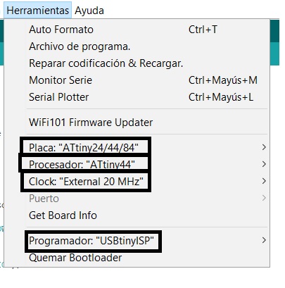
In order to upload our first code, which will be the blink, we must configure the IDE tools with the following data:| Board | Attiny24/44/84 |
| Processor | Attiny44 |
| Clock | External 20 Mhz |
| Programmer | USBtinyISP |
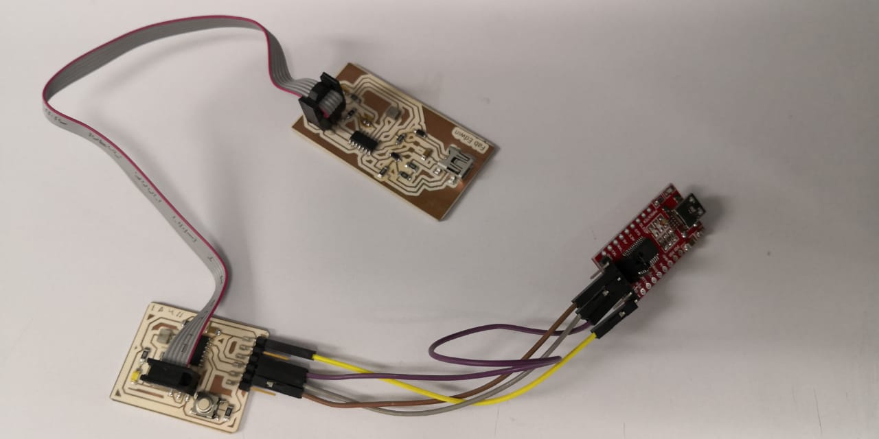
 Now we will need our ISP and an FTDI. The function of the ISP is to burn the bootloader, which prepares the microcontroller to receive the code.
We use a FTDI, the function is converting the serial transmissions to USB signals in order to allow Attiny compatibility with the computer with the data transmission pins: Tx and Rx. Below is a picture of the necessary connection.
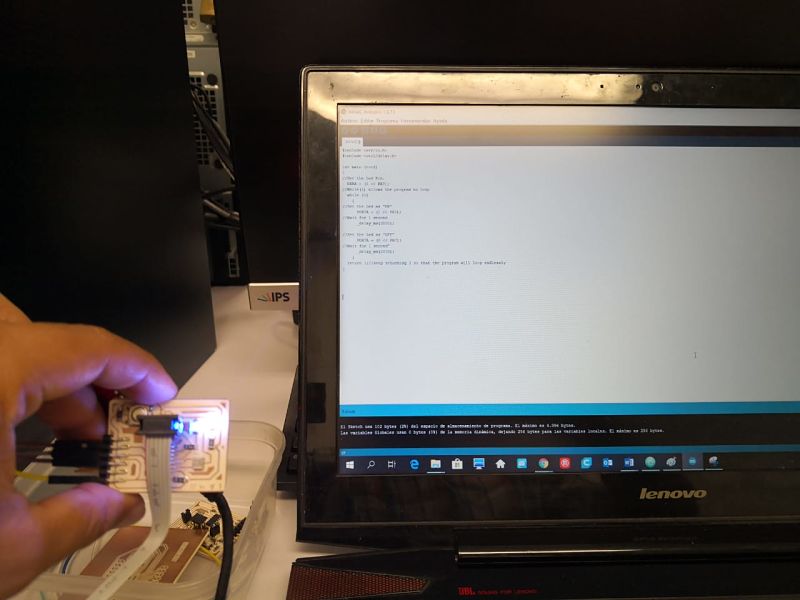
 Having the ISP, the FTDI and the connected HelloWorld proceed to carry out the programming following the following steps:
- Compile the program.
- The bootloader is burned.
- Upload the code.
This video is from button code
And this one is the test button code
Another programs and languages
C
To program in C, I reviewed this tutorial to be able to understand the code used by a co-worker who made the Fabacademy last year, Carlos Herbozo. Using the code he has I charge the code and check that if the code works.#include
#include
int main (void)
{
//Set the Led Pin.
DDRA = (1 << PA7);
//While(1) allows the program to loop
while (1)
{
//Set the Led as "ON"
PORTA = (1 << PA7);
//Wait for 1 second
_delay_ms(3000);
//Set the Led as "OFF"
PORTA = (0 << PA7);
//Wait for 1 second"
_delay_ms(2000);
}
return 1;//keep returning 1 so that the program will loop endlessly
}  In the C language it is important to know the difference between ports A and B.
Ports A are bidirectional ports of 8 bits that are normally used as analog pins, while ports B are bidirectional 4 bits and are usually used as digital pins.
For the assignment of inputs we will use the analog converter (page 129 from the datasheet of attiny44) and the assignment of outputs we use the PWM signal (page 69 of the datasheet). We must define the pin to use, in this case the line DDRA = (1 << PA7) indicates that we will use the pinA7.
The line PORTA = (1 << PA7) indicates that we are setting its value to 1, that is, HIGH. While the line PORTA = (0 << PA7); we force its value to a 0, that is, a LOW.
The while (1) symbol symbolizes the start of the operation loop. Analyzing the Neil’s code on the hello world we can see that he activates the clock using the following lines:
// set clock divider to / 1
//
CLKPR = (1 << CLKPCE);
CLKPR = (0 << CLKPS3) | (0 << CLKPS2) | (0 << CLKPS1) | (0 << CLKPS0);
//This estructure is:
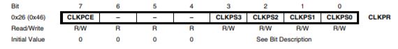
Bit 7 – CLKPCE: Clock Prescaler Change Enable The CLKPCE bit must be written to logic one to enable change of the CLKPS bits.
Bits 6:4 – Res: Reserved Bits These bits are reserved in the ATtiny24/44/84 and will always read as zero
Bits 3:0 – CLKPS3:0: Clock Prescaler Select Bits 3 - 0 These bits define the division factor between the selected clock source and the internal system clock.
What else can I learn?
Many years ago in the university I started to program microcontrollers and there was the option of creating interruption subroutines,besides being able to control the watchdog. I hope in the future to be able to understand and use these concepts in a way, since they are very important for the programming and use of the internal memo.Atom
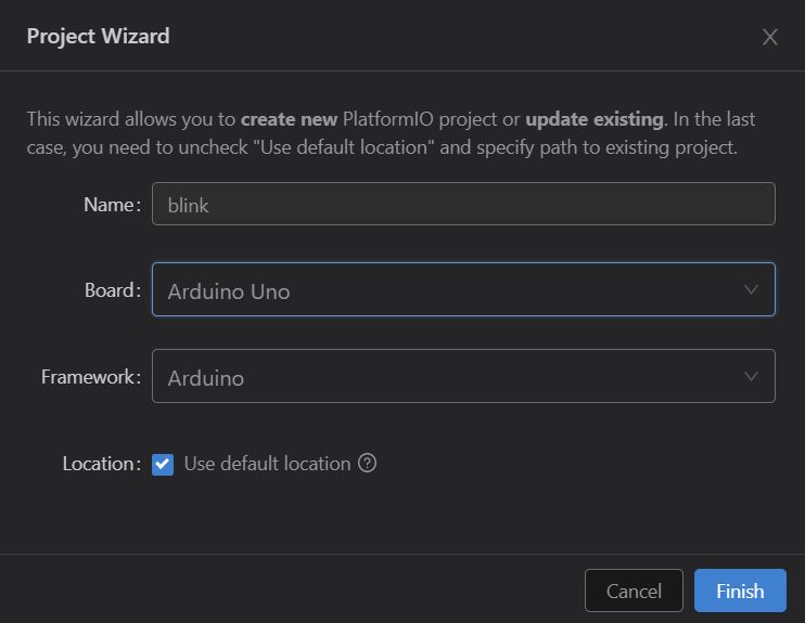
Investigating about ways of programming, I have seen that if an Arduino board can be programmed by the Atom. I found this tutorial that explains in detail how to prepare the atom for programming. Below is an picture in which I have prepared the Atom for programming, as well as some codes already made.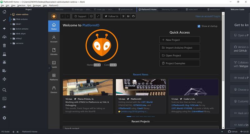 My first test was with an Arduino Uno, first I create a new project like the picture:
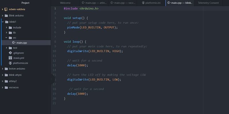
 Edit the main file from src folder with the same code:
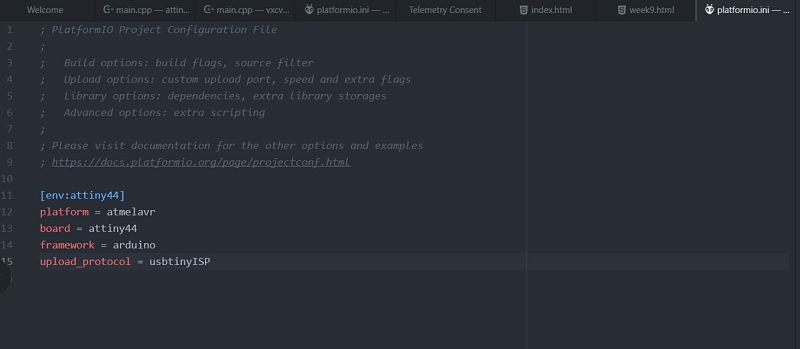
 Finally I upload the code in an Arduino board, but I can not do it with my ISP and my hello world board, I read all the tutorial but I can not do it.
I even modified the platformio.ini file with the communication protocol, but I did not have the expected results.
Finally I upload the code in an Arduino board, but I can not do it with my ISP and my hello world board, I read all the tutorial but I can not do it.
I even modified the platformio.ini file with the communication protocol, but I did not have the expected results.
Group assignment
For the group assignment, we use a Raspberry Pi Zero W, my contribution was the programming of that board. The laboratory has some digitals inputs(3 buttons) and digital outputs(3 leds).After reading the pin connection of the raspberry, this is the connection of the board and raspberry.
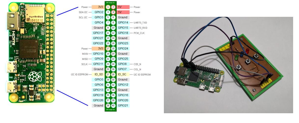 For the programming I base from this tutorial and this is the code:
from gpiozero import LED
from time import sleep

led=LED(7)

while True:
		led.on()
		sleep(1)
		led.off()
sleep(1)from gpiozero import LED, Button
from signal import pause
led=LED(7)
button=Button(27)
button.when_pressed=led.off
button.when_released=led.on
pause()To see all the documentation of the group work, you can visit the CIT page. Both structures have a great similarity: we must define the pins to use and create all the programming in a single loop.
The problem of using the raspwberry architecture is the incorporation of libraries to use their ports, while in the arduino libraries are used to improve and summarize the code.
On one side of the raspberry if it allows to perform tasks in parallel to have a microprocessor, while the arduino is not necessary to use libraries unless they are peripheral sensors or actuators.
For costs, the arduino is the best option while by code, only the raspberry would be used if we want to use multitask functions.
Download files
You can download this files Here:Arduino Code
Blink
Button
Test Button
C
Blink C
Platformio
Blink Atom
Raspberry
Blink Raspberry
Button Raspberry
Atmega board
Board
Schematic