
Interface and Application Programming.
Communication
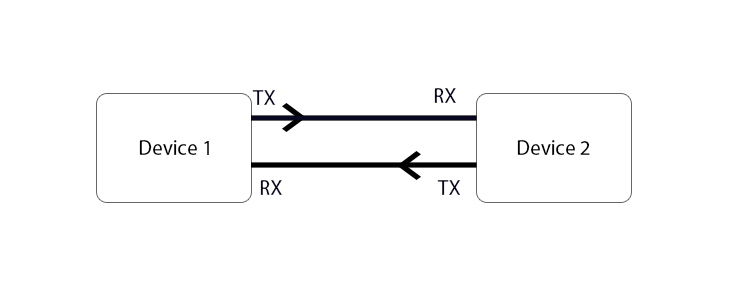
The main objective of this week is to create a graphical user interface (GUI) that allows communication between our controller and a computer. To simplify the task, I will use the Serial communication learned in week 14.
 Among the main objectives of the Fabacademy is to learn new work tools and improve those already known, I will use the Java programming language with the NetBeans software and the wireless serial communication using the Bluetooth.
Board
After some weeks, it’s time to work with my atmega380p board. My first try was in the week 9 but it doesn’t work because some tracks lose continuity.
The second try was in the week 11, the bootloader burned but I can’t upload my code.
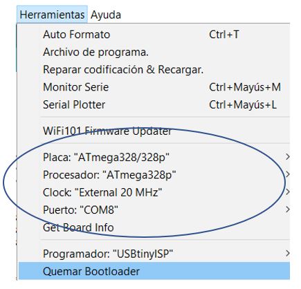
After an investigation guided by my local instructor, I found the problem of load failure: my board used a 20Mhz resonator while the Arduino uses a 16Mhz oscillator.
I found this tutorial and define my board on the IDE like the picture.
 The next step is the wiring using the ISP and the FTDI to link it. As the bootloader had been done previously, it is not necessary to do it again, the only thing we must do now is load the code.
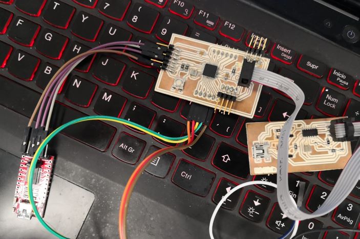 We use any code and we can see that if it goes up correctly, from now on I will use my atmega328 for the following weeks.
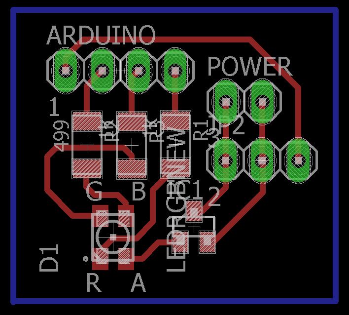
However, on this week we need some inputs or outputs, for that reason I made another board, but in this case only use a RGB led and connection for a Servomotor like the picture.
NetBeans
Taking advantage of a course on ethernet communication with Arduino that I followed last year, I take advantage of the NetBeans programming environment.
 This is a programming software specialized in the Java programming language, to be able to understand the basic principles of java with Arduino.
I read several tutorials from the panamahitek page, it is worth mentioning that these are tutorials in Spanish.
The main considerations that we should have with NetBeans are the following:
- Unable to program Arduino using the Java language.
- Arduino communicates with the computer through Serial Communication.
- To allow Java to establish communication with the Serial Port, it is necessary to install library drivers. (https://sourceforge.net/projects/arduinoyjava/)
- When creating a program in Java and establishing communication with Arduino, the Serial Monitor is being replaced by a graphical interface.
- Java notices every time Arduino sends data.
- In Java it is possible to graph the data that we read in the sensors connected to Arduino.
- Graphical interfaces in Java add versatility to projects in Arduino.
On Off
The first GUI that I will perform is the simple activation of the RGB LEDs using Java. First thing I must do is create a new project with a JFrameForm, inside this format we create our GUI with the use of buttons, as described in this tutorial.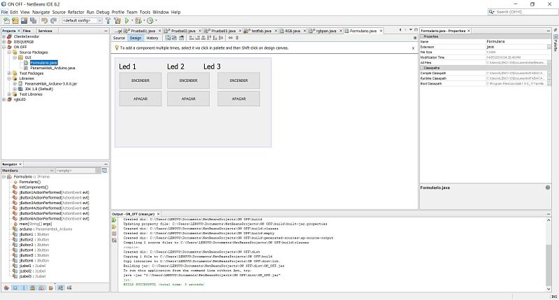 Once finished performing the GUI, we will start to edit the source code by clicking on source. Inside the code we must initialize the Arduino using the library, as the picture.
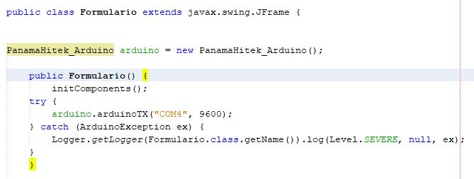 From the IDE of the arduino we check the port where the arduino is located and the transmission speed, in my case it is the COM4 and at 9600 baud.
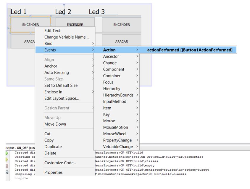
The next step is program the function of each button, to do just right click on the button and select the action option.
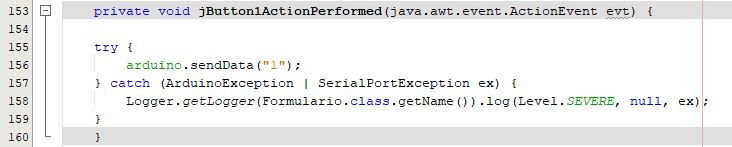
 We write the following command: arduino.sendData("1"), an error will be displayed but pressing alt + enter we select the try / catch option to be able to correctly link its operation to the Java statements.
The result must be like the following picture.
 We must perform the same steps with the other buttons modifying the values with a 2 and 3 for the activation, while the shutdown will always be 0.
In the arduino ID we load the following code (the code will be found in the downloads section). As a particularity, we must use the serial software library, in this way if we can see the serial monitor.
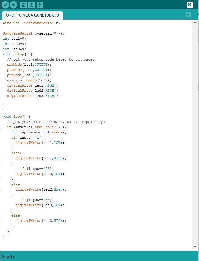 Below is a small video of its operation.
PWM
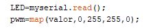
The next step I make is the use of PWM using sliders. Each slider must have a minimum value of 0 and a maximum value of 255, as shown in the picture.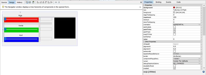 For this case, a method is created to "set" the data that we will send to microcontroller. As the values that we will send will be between 0 and 255, what the software does is send them figure by digit.
If we are going to send for example the 255, microcontroller will receive the 2, then the 5 and then the other 5.
For this case, a method is created to "set" the data that we will send to microcontroller. As the values that we will send will be between 0 and 255, what the software does is send them figure by digit.
If we are going to send for example the 255, microcontroller will receive the 2, then the 5 and then the other 5.What we will do with microcontroller will be to receive the hundreds, tens and units. The 2 we multiply it by 100, the 5 by 10 and the last 5 we leave it that way. Then we add them: 200 + 50 + 5 = 255. However, for this to work first you have to send the hundreds, then the tens and finally the units. If you control a 1, microcontroller will multiply it by 100 and then we will not obtain the desired results. What we will do to prevent this from happening is to send "001". So, microcontroller will do the following: (0) * 100 + (0) * 10 + 1 = 1.
The same when there are dozens. If we send the 10, we must do it in the following way: «010». microcontroller will interpret it in the following way: (0) * 100 + (1) * 10 + (0) * 0 = 10.
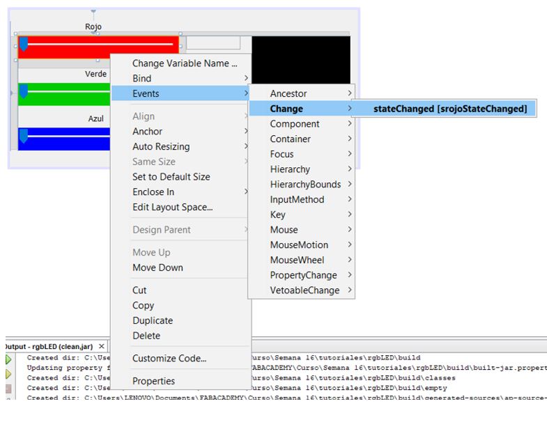
 As done with the On and Off button, we will perform the change action according to the position of the slider, as seen in the picture.
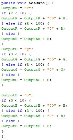
 The code used by each slider will be the following.
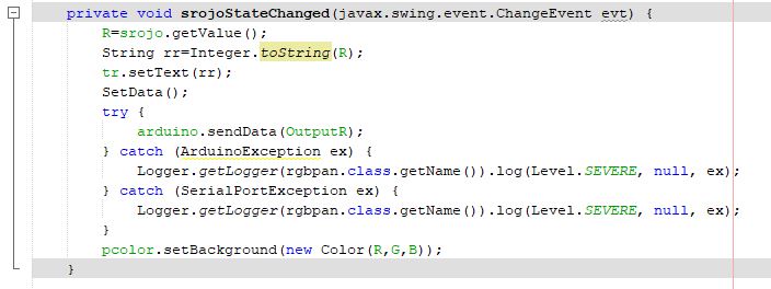 What we do is save the reading of the slider in a variable, convert it into a text to be able to write it in a text box and then send that data to the SetData function, after the SetData is sent to the microcontroller and the color of the box is changed according to the color.
In the arduino ID we load the following code (the code will be found in the downloads section).
 Below is a small video of its operation.
We can appreciate a problem in its operation, this is detailed in the part of problems, which is found ahead.
A servomotor has a very similar operation to the PWM, with which I will try to perform the control of the Servo with another type of programming environment, with the APP Inventor being selected.
App Inventor
App Inventor is an online software development environment created by Google Labs for the development of applications for the Android operating system.
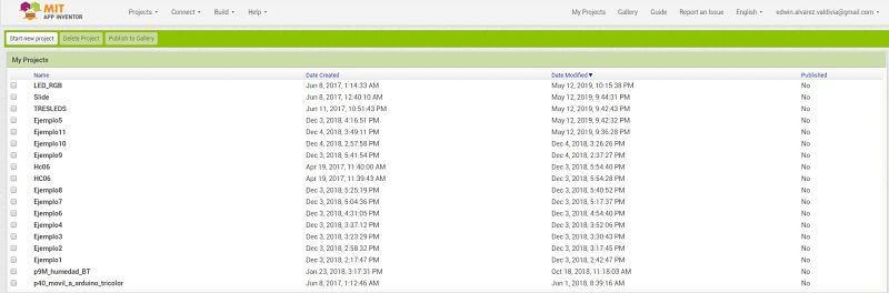
This environment is quite friendly, and I have experience with the creation of apps, as you can see the projects developed as tests and final applications related to the Arduino.
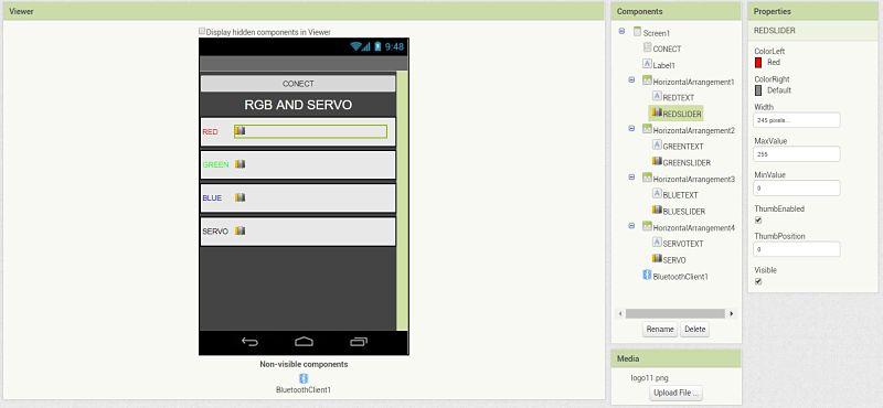
 We will use a list picker for the connection of the Bluetooth and some sliders for the programming of the RGB and the servomotor.
The text parameters are modified to give the desired shape and the maximum and minimum values of the sliders as shown in the picture.
We will use a list picker for the connection of the Bluetooth and some sliders for the programming of the RGB and the servomotor.
The text parameters are modified to give the desired shape and the maximum and minimum values of the sliders as shown in the picture.
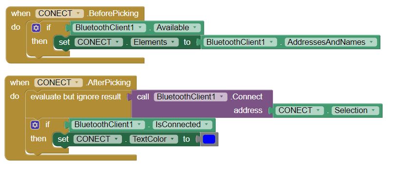
 The next step is to configure the connectivity of the bluetooth, for this we select the options before picking and after picking of the list picker.
The before picking must create some elements to the list picker, which will be the addresses and names of the existing bluetooth devices.
In the case of after picking you must select the address of the bluetooth module from the previous list picker.
The next step is to configure the connectivity of the bluetooth, for this we select the options before picking and after picking of the list picker.
The before picking must create some elements to the list picker, which will be the addresses and names of the existing bluetooth devices.
In the case of after picking you must select the address of the bluetooth module from the previous list picker.
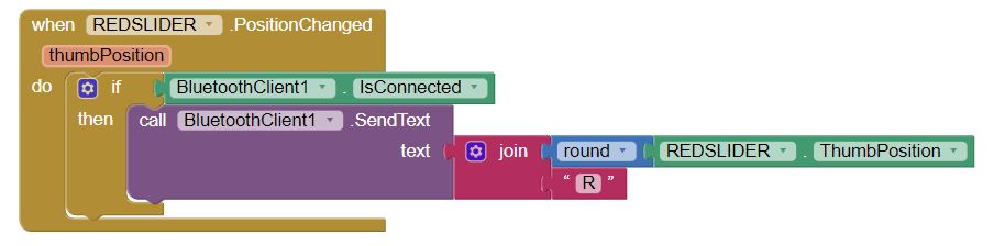
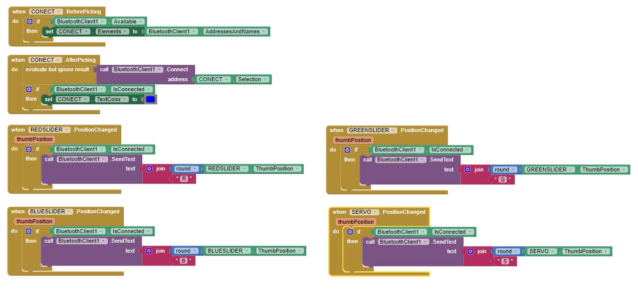
 To send the data to the microcontroler will be done in text form in which a letter is assigned to define the slider and then its value.
 The blocks for the sliders of the remaining led and the servomotor must be repeated.
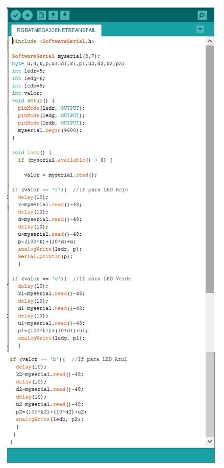
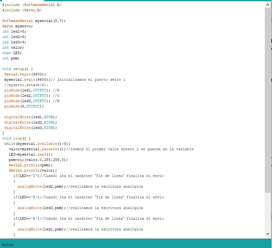
 The following code is loaded in our microcontroller.
 To install the application, click on build and choose the QR code format. From an Android phone the MIT AI2 Companion application is downloaded and the code is scanned, having the installation of our application.
Once installed, the test of our application is performed, then a demonstration video.
(app video)
Problems
In the netbeans the operation of the PWM did not occur in the expected way, I have reviewed many tutorials and the way of programming is similar to mine, but the videos are at least 2 years ago.
The conclusion I can reach is that the bookstore is new and has that drawback or there is a new way to program.
For this reason, I decided to program with the app inventor.
One problem I found when trying to perform the control with the bluetooth was that the rgb LEDs are in reverse, so I must make a change in the programming, as shown in the picture
 The second big problem was with the iteration of the PWM and the servomotor.
Independently works very well, but when integrating the servo there are problems. As seen in the week of outputs, the servomotor library can cause interference with other output pins.
Group
Working
Download
You can download this files Here:
Board
Schematic.
Board.
Code with netbeans
On Off code.
PWM code.
Code with Bluetooth
PWM code.
NetBeans Projects (.zip)
On Off project.
RGB project.
APP Inventor (.apk)
RGB project.