Week 12: Ouput Devices
Individual assignment
This week we will add an output device to a microcontroller board that we will design and program it to do something.
Data Sheet
In this week we will work with board outputs, these devices change a variable that we are measuring with different sensors. In the FabLab CIT we have several types of analog devices such as a speaker, DC motor, servomotors and stepper motor; In addition, digital devices such as an LED, Button and an LDC display.
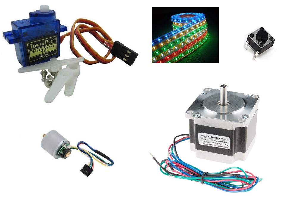 Fig.01 - Devices
 For my final project I will use servomotors to move the coverage, I am still testing the prototype at a scale of 1: 5, so I am using the CS-939MG data sheet . However, I'm going to try the Attiny45, that's why I checked the data sheet to know which pins are PWM and I got the connection between the components.
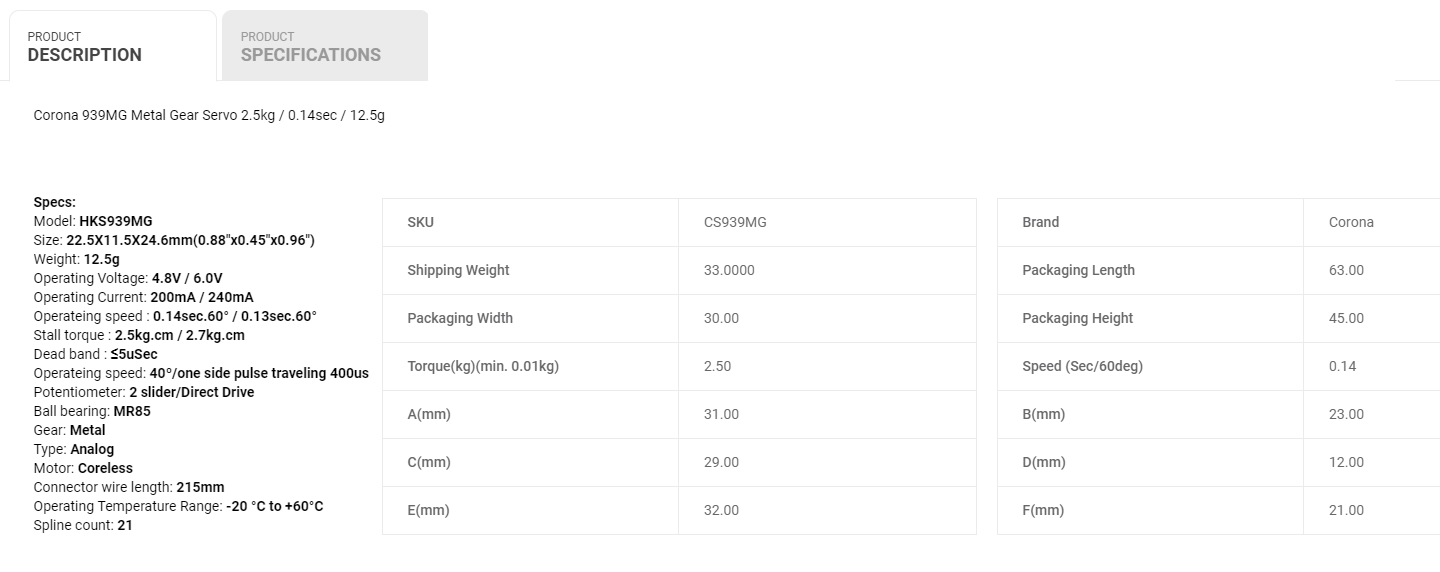 Fig.02 - Data Sheet
 PWM
Pulse Width Modulation, or PWM, is a technique for getting analog results with digital means. Digital control is used to create a square wave, a signal switched between on and off. This on-off pattern can simulate voltages in between full on (5 Volts) and off (0 Volts) by changing the portion of the time the signal spends on versus the time that the signal spends off. The duration of "on time" is called the pulse width. To get varying analog values, you change, or modulate, that pulse width. If you repeat this on-off pattern fast enough with an LED for example, the result is as if the signal is a steady voltage between 0 and 5v controlling the brightness of the LED.
In the graphic below, the green lines represent a regular time period. This duration or period is the inverse of the PWM frequency. In other words, with Arduino's PWM frequency at about 500Hz, the green lines would measure 2 milliseconds each. A call to analogWrite() is on a scale of 0 - 255, such that analogWrite(255) requests a 100% duty cycle (always on), and analogWrite(127) is a 50% duty cycle (on half the time) for example.
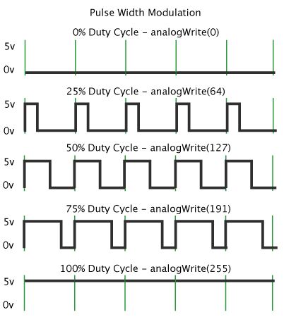 Fig.03 - PWM
 The PWM pins of the ATtiny45 are seen in the image
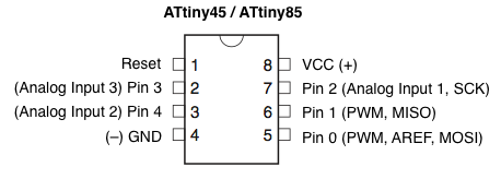 Fig.03 - PWM ATtiny45
 PCB Design
The ATtiny45 symbology is different because it has fewer connection pins, so in this design I consider a servomotor.
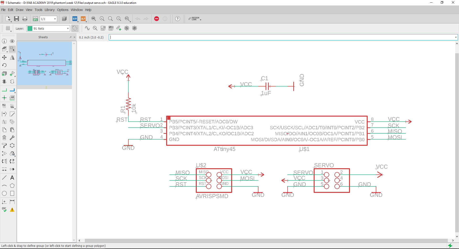 Fig.03 - Ouput Schematic
 With the practice I connected the routes with in less time, being a very small plate consider the measure of the route lines with a width of 4.
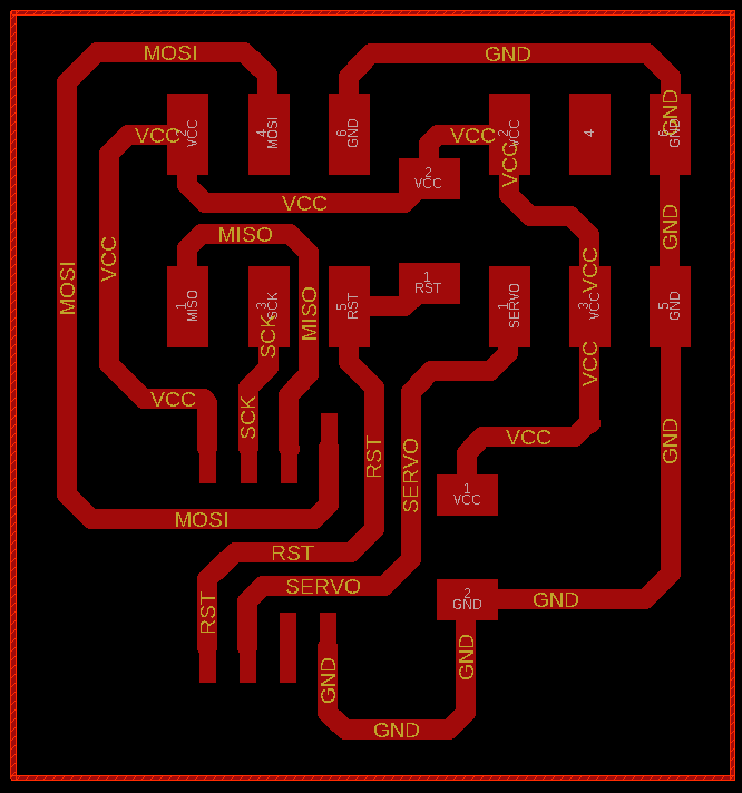 Fig.04 - Ouput Board .
 I turned off the board layers and exported the routes, the result looks like in the image.
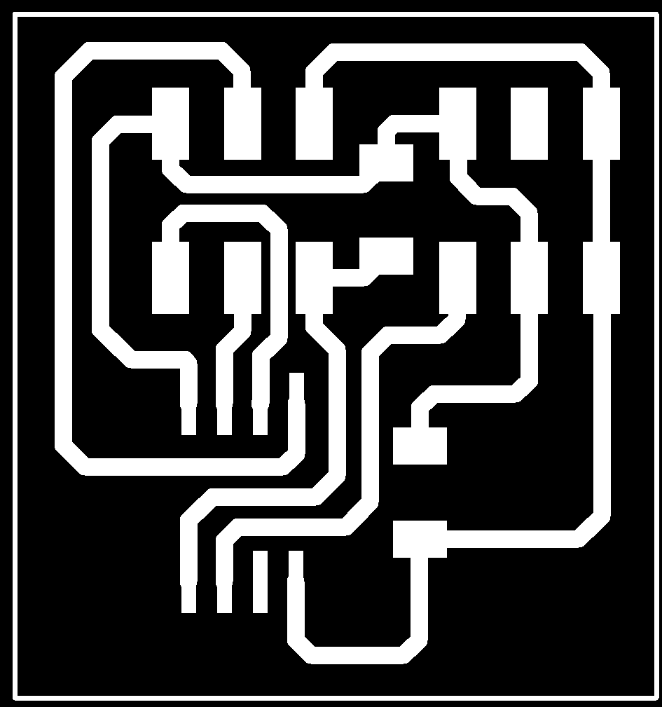 Fig.05 - PNG
 After cutting it in the CNC, the components were soldered with flux and continuity with the multimeter was proved.
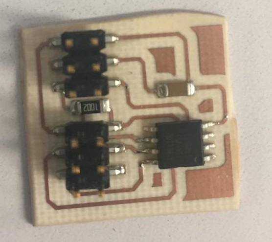 Fig.06 - Output Device
 Programming
To complete the programming, it was sufficient to connect the ISP to the Output board and connect it to the servomotor.
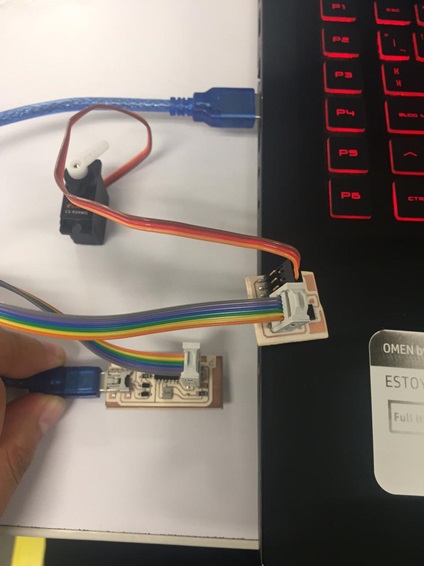 Fig.07 - ISP + Ouput Device + Servomotor
 The programming of outputs seems more tedious to me since I notice that the examples of Inputs devices are standard, but the final result of the Outputs devices vary arbitrarily in all the users. That is why, to achieve programming I used Neil's codes . With the code I managed to complete the bootloader burn.
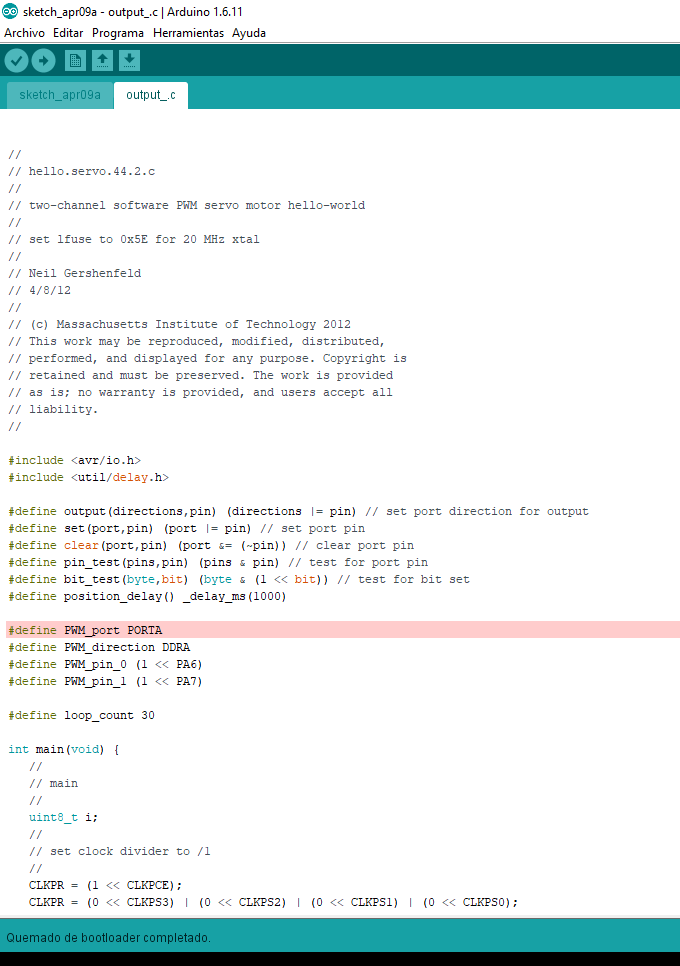 Fig.08 - Bootloader
 I changed and declared the PWM pins, however, the codes did not work, until I noticed that Neil had used two servomotors. The solution was to eliminate all the data of the second servomotor and thus it was possible to upload the programming
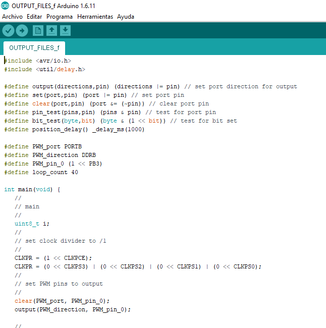 Fig.09 - Solution
 After the corrections, the servomotor was programmed.
If we modify the loop we can increase the speed of the servo; On the other hand, by changing the delay we can obtain the angles we want to give to the servomotor.
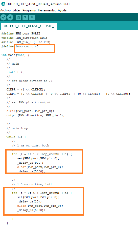 Fig.09 - Code
 In the video I will show that if we modify the values of the delay_us we can originate the angles that we want, in my case I will generate the angles 20,45,90,135 and 180.
Files
You can download group files here.
Arduino CodeSchematic
Board
PNG
Grupal assignment
Measure PWM RGB
The modular pulse regulation or PWM, is a way to represent an analog output using the digital signal. The use that we give to the PWM is the regulation of the brightness of the Red LED. With the use of an oscilloscope, we proceed to measure the pulse width in a loop, constantly appreciating this regulation.
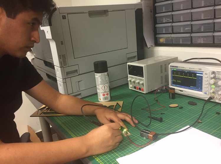 Fig.11 - PWM RGB
 Below is a video with the use of PWM
To see all the documentation of the group work, you can visit the CIT page.