Electronics Production
Group work
In Electronic design week our group work is to know the Our PCB milling machine, SInce most of are new to pcb milling we are also wanted to know the process of PCB milling in deep and how different parameters of Fab modules effects the milling operations.
Things we learned in group assignment :
Introduction to PCB
PCB Stands for "Printed Circuit Board". A PCB is a thin board made of fiberglass, composite epoxy, or other laminate material. Conductive pathways are etched or "printed" onto board, connecting different components on the PCB, such as transistors, resistors, and integrated circuits.
PCBs are used in both desktop and laptop computers. They serve as the foundation for many internal computer components, such as video cards, controller cards, network interface cards, and expansion cards. These components all connect to the motherboard, which is also a printed circuit board.
While PCBs are often associated with computers, they are used in many other electronic devices besides PCs. Most TVs, radios, digital cameras, cellphones, and tablets include one or more printed circuit boards. While the PCBs found in mobile devices look similar to those found in desktop computers and large electronics, they are typically thinner and contain finer circuitry.
Materials for PCB
a woven fiberglass cloth impregnated with an epoxy resin. Low water absorption (up to about 0.15%), good insulation properties, good arc resistance. Very common. Several grades with somewhat different properties are available. Typically rated to 130 °C.
FR-1 is a hard, flat material that consists of a thin layer of copper over a non-conductive phenolic resin. It’s usually about the thickness of two or three credit cards.
Unlike FR-4, which is fiberglass-based and generates dangerous glass-shard dust when milled, FR-1 is safe to use if you keep it away from your eyes, lungs, and skin. We recommend vacuuming up the debris after you’re done milling (never blow on it).
phenolic paper or phenolic cotton paper, paper impregnated with a phenol formaldehyde resin. Common in consumer electronics with single-sided boards. Electrical properties inferior to FR-4. Poor arc resistance. Generally rated to 105 °C.
clad with thermally conductive thin dielectric - used for parts requiring significant cooling - power switches, LEDs. Consists of usually single, sometimes double layer thin circuit board based on e.g. FR-4, laminated on aluminum sheet metal, commonly 0.8, 1, 1.5, 2 or 3 mm thick. The thicker laminates sometimes also come with thicker copper metalization.
Introduction to MDX-20
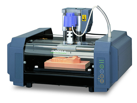
Click here to know source of image.
Rolans MDX-20 is tiny desktop cnc machine which can do many operations based on substraction manufacturing , it can do 3d milling, 2.5d milling, 2d milling efficiently. Thats why machine comes in multi purpose category, one can do pcb milling for circuit design and on other hand it can also be used for the Molding casting purposes.
Specifications :
| Model | MDX-20 |
| XY table size | 220 (X) x 160 (Y) mm ( 8-5/8 x 6-1/4 in.) |
| Max. operation area | 203.2 (X) x 152.4 (Y) x 60.5 (Z) mm (8 (X) x 6 (Y) x 2-3/8 (Z) in. ) |
| Operation humidity | 35 to 80 % (no condensation) |
| Max. table load weight | 1000 g (2.2 lb.) |
| Interface | Serial (RS-232C) |
Modeling Functions :
| Tool chuck | 6 mm or 1/8 in. tool chuck included |
| Spindle motor | 10W (DC motor) |
| Software resolution | 0.025 mm/step (0.000984 in./step) |
| Mechanical resolution | 0.00625 mm/step (0.000246 in./step) |
| Revolution speed | 6,500 rpm |
| Feed rate | 0.1 to 15 mm/sec. (0.00393 to 9/16 in./sec. |
| Acceptable tool | Endmill, Drill |
| Export file formats | DXF,VRML, STL, IGES, Grayscale, BMP |
Click here to get source of imformation
How it works ?
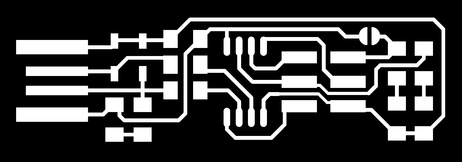
In png files whole milling machine works on principal of monochrome.. machine will generate tool path on basis of Black and white inteersection , on the edges of black and white colors machine will cut and it will only cut towards black color if some offset is given on settings , Thats why traces should always be in white one.
Below is example of png image ( ISP ATTINY 45 ) designed by Brian. it is example on png(monochrome format), al the traces will bw white.
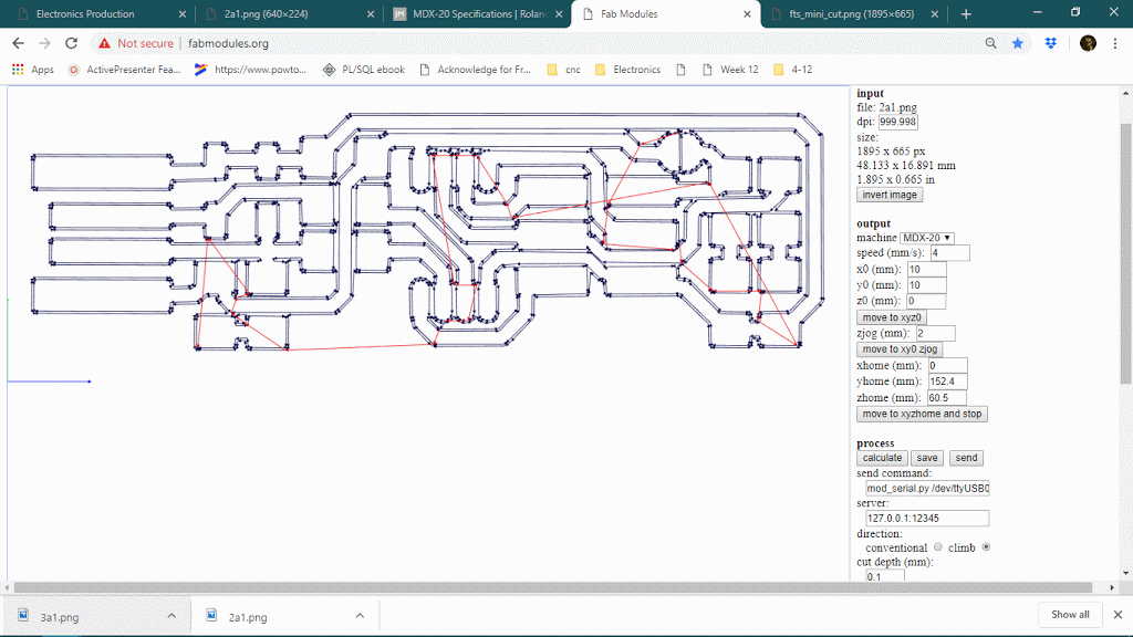
Fab module
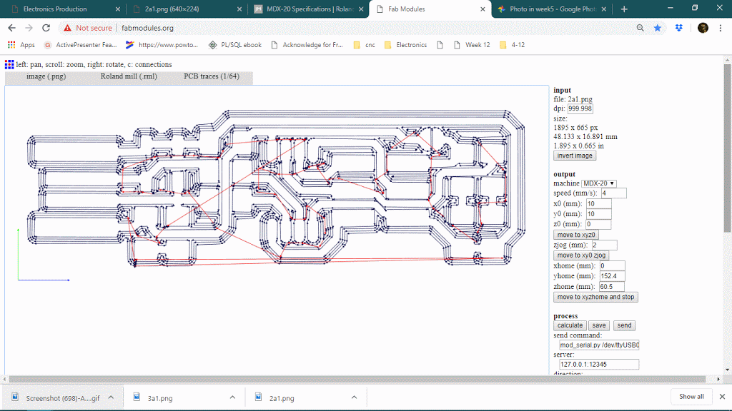
we are using linux base system for PCB milling. I've posted work of fab-modules here, one may have to fullfill some prerequisite before using the fab module , click here.
After importing the png file we checked main 2 parameters and its effects ion toolpath. these two parameters matters beacause it decides how traces will come and how much area of the black portion will cut , it related to time also and when trces are so much near it may wipe out traces , then we have to decrease offset and overlay accordingly.
Number of offset
Number of offset is changing from the 4 to 1 , its minimum value is -1 , first in 4 to 1 , purpose of parameter is clear , we can see below while changing the offset to 4 to 1 cut outer cut area will be less , it will reduce time for sure and for closer traces this settings can be chnage to 2 , but there are chances of short and uncut traces also, it may effect device functionality.
Note :
It is showing white area is safe , but may not be if traces are much closer, it may cut mnore portion of copper traces on closer side.
Number of offset - -1
This is special purpose offset setting, it will cover whole black area . it is used for bed leveling of machine. see below
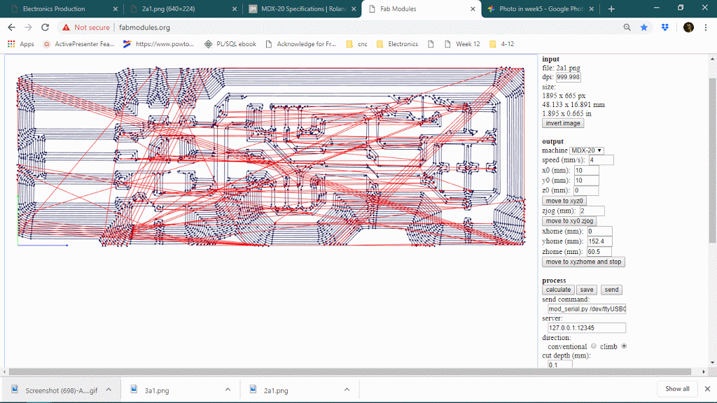
Offset overlay
One can also have 4 offsets and decrease the cut area. it will not save time but it can ensure good trace cut beacause tool will go through sut area more if offset overlay increased.
Offset overlay means ghow much new toolpath shift from adjacent one in terms of tool diameter, if offset is 70% new cut area will be 30% (tools 30 % diameter will be on new cut area) and 70 % will be overlap. below is giif of increasing the overlay , increasing the overlay toolpath will be wider and there will be chances of uncut areas between toolpath.
Line Test
Through the group assignment, we will go through the process of fabricating a Traces-width board, assessing how separated can our traces be, as well as how thin they could potentially be. The board we will be machining is found below, and we will be using copper PCBs machined in either Modela MDX-20
.The traces png file to be machined with a 1/64” tool:
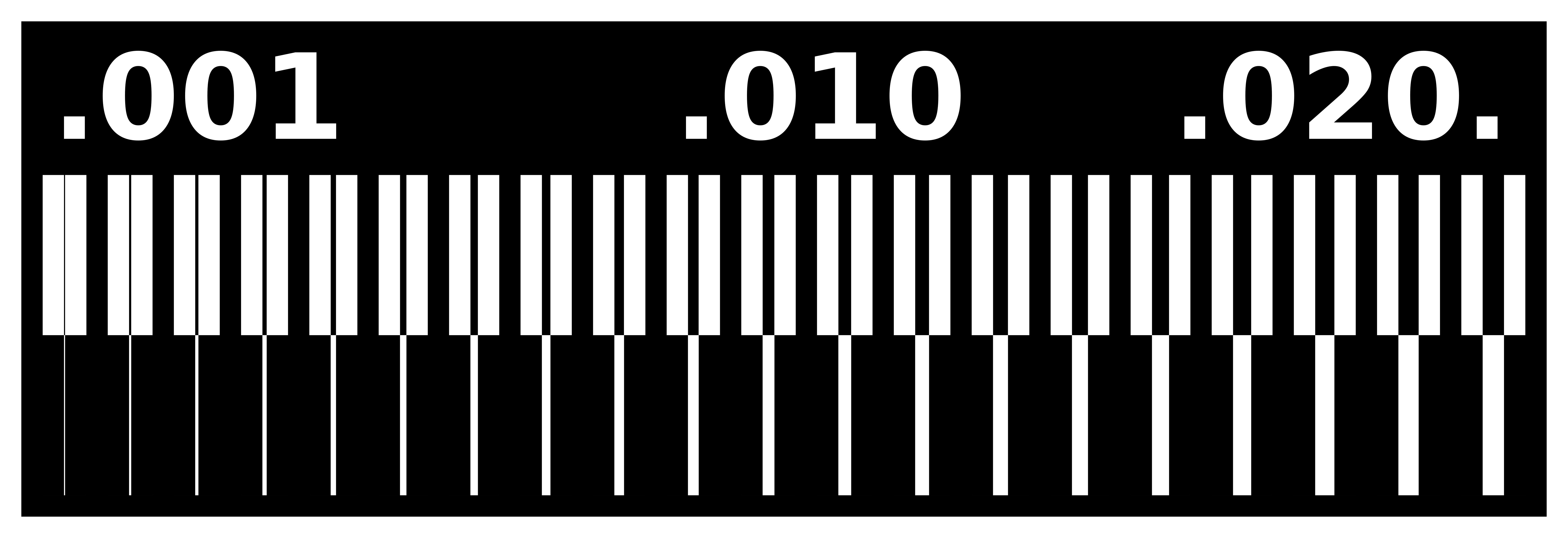 Download
The Cut png file to be machined with a 1/32” tool:
 Download
Both png files will be passed through the FabModules. Note that this tool will detect changes between BLACK and WHITE in the png files and generate a path in it for the machining process. The settings selected for the PCB traces are:
The settings selected for the PCB outline (only detailing the ones that are different):
Fab modules
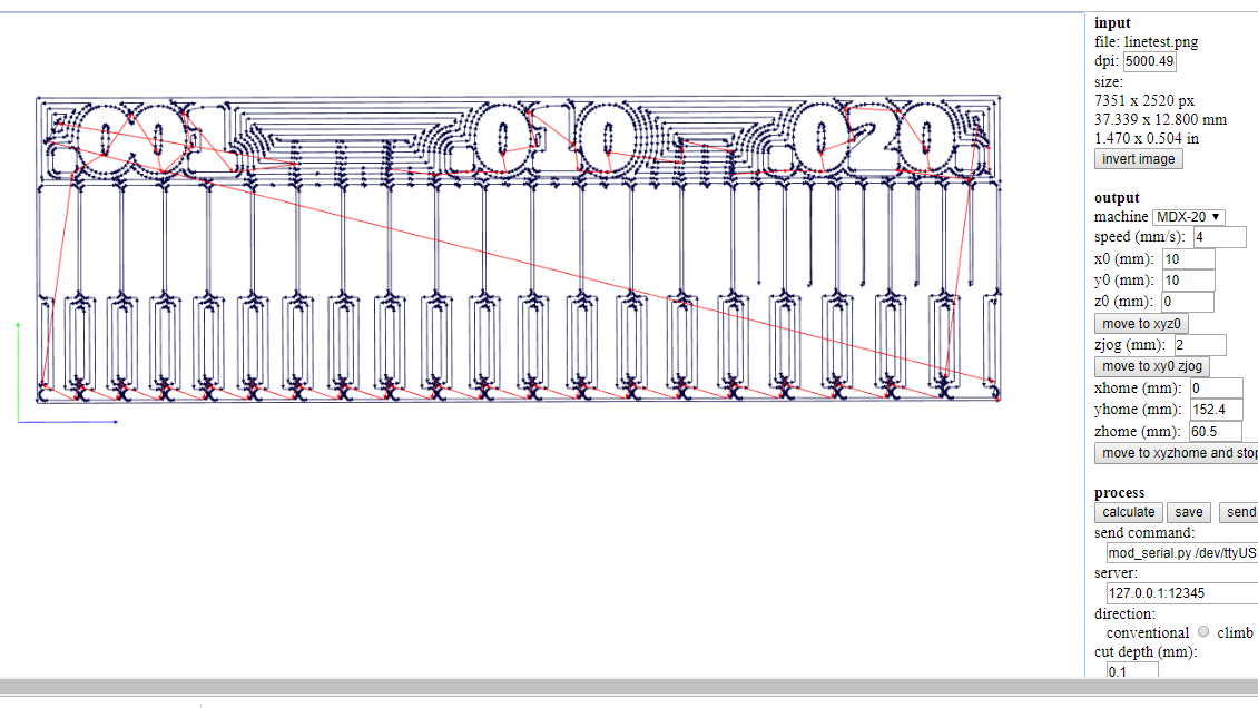
Output
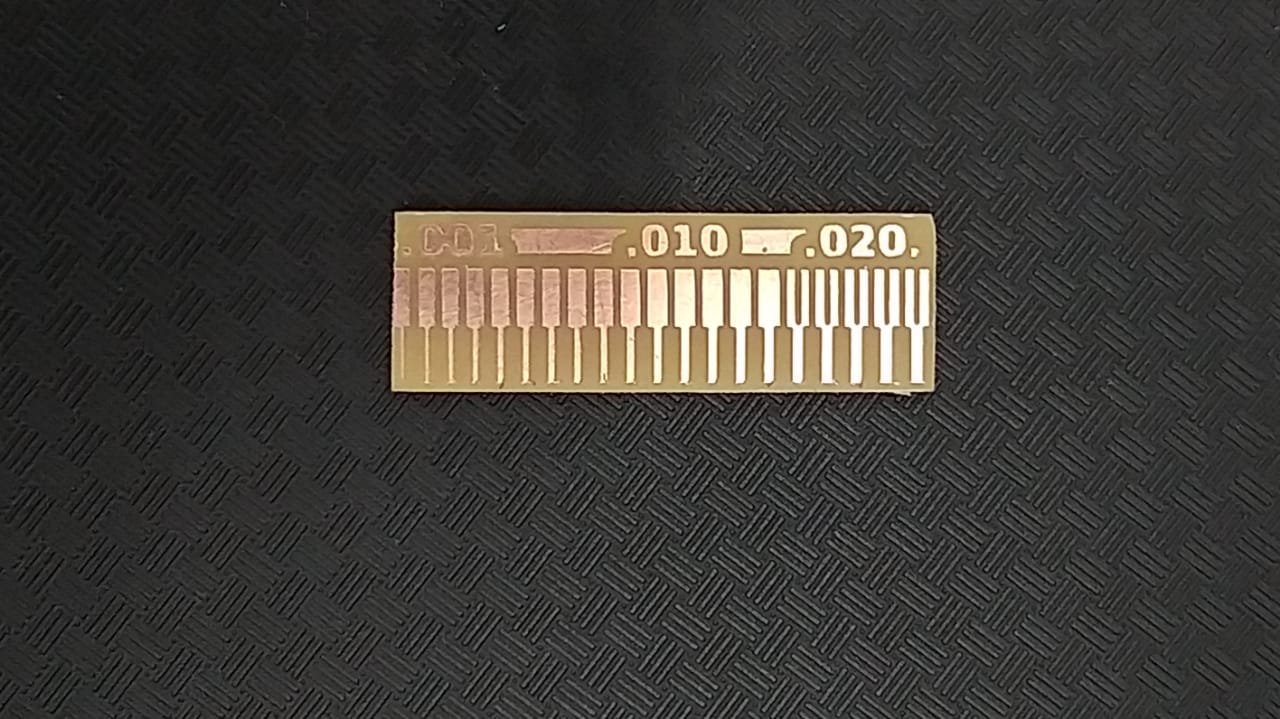
Conclusion about line test
in fab modules toolpath cant be generate less then some notches , as we can see below if notch dimention is below the tool diameter it will not generat toolpath so , notch width should above the (0.4mm or 1/64 inch) and we can use this imformation in our pcb design.
General Conclusion for Fab modules
for Fab module