Embedded Programming
Week 09
The assignment about embedded programming again contains a group and an individual task. The individual part is more about the hello world board developed in the previous week, where it is also about understanding the processor itself and doing something with the hello world board afterwards. In group assignment we should compare the performance and development workflows for other architectures.
Individual assignment
Datasheet for the ATtiny44
Two weeks before I made the hello world board. The microcontroller I used is an ATtiny44, which I have to understand now. In this week we should read the datasheet about the microcontroller, with flattering 286 pages and try to understand it. The last 100 pages are only graphs, but the previous pages had it all. It’s unbelievable what such a small microcontroller contains. The table of contents is on page 281.
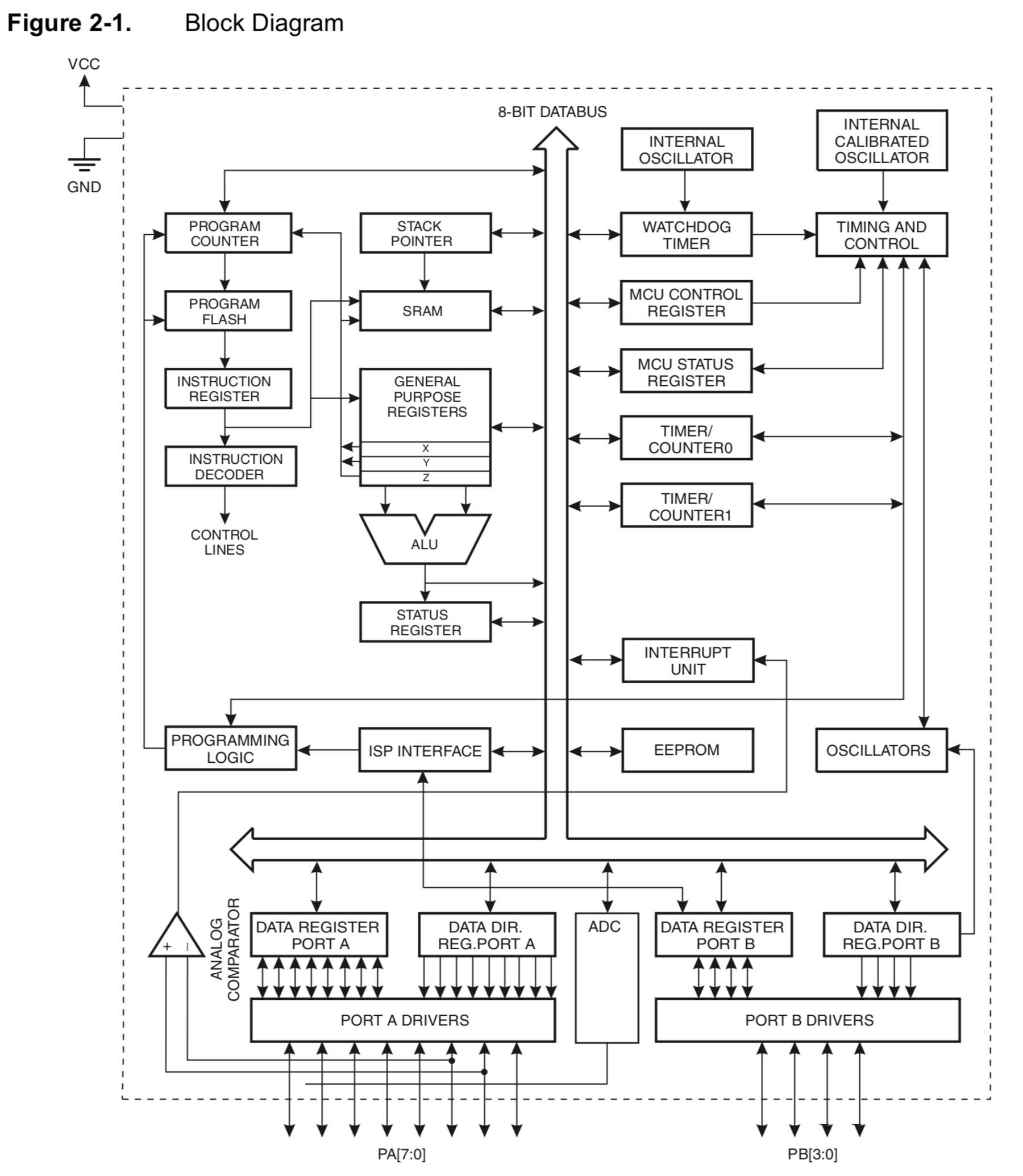
The ATtiny44 has some main features that I would like to introduce briefly:
- 32 x 8 General Purpose Working Registers
- One 8-Bit and One 16-Bit Timer/Counter with Two PWM Channels, Each
- 10-bit ADC
- 4K Bytes of Flash Program Memory
- 256 Bytes of Programmable EEPROM
- 256 bytes SRAM
- 12 programmable I/O Lines
- In-System Programmable via SPI Port
- Low Power Idle, ADC Noise Reduction, Standby and Power-Down Modes
- Internal Calibrated Oscillator
- On-Chip Temperature Sensor
- an operating Voltage from 1.8 up to 5.5V
- an Industrial Temperature Range: -40°C to +85°C
The first google suggestion is always the “arduino pinout”, because you have to find out which pins at which position take over which function. Of course you can find them in the datasheet:
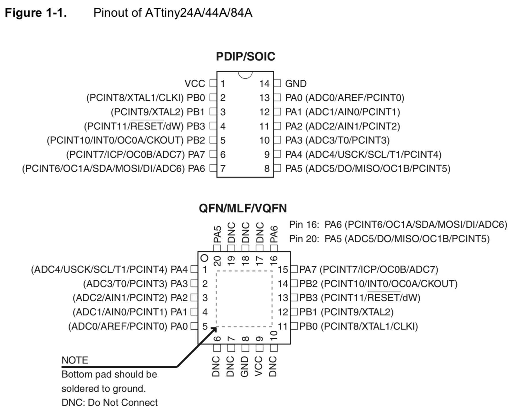
It can be seen that there are two groups of ports which, according to the data sheet, are classified into group port A (PA0 to PA7) and port B (PB0 to PA3). The difference is that the group port B is 4- bit bi-directional I/O ports, whereas the group port A is 8-bit bi-directional I/O ports. The ports of group A can also be used as alternatives for the SPI and more.
Furthermore, it was also relevant to set fuses for the previous assignments. These are used when the software is no longer allowed to use them, for example as a security function. It is also used to set the internal clock or to activate the bootloader. So to speak you can change the configuration of the microcontroller by setting fuses and in the worst case you can also brick it.
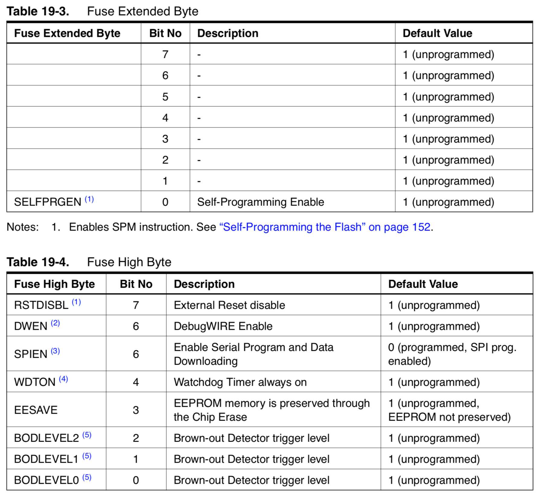
The table shows what the default values are and gives a small description.
Program my board
In the next section I describe what I did with my hello world board. There were two components I could use: One was an LED and the other was the button. So I had three options:
- Use LED
- Use button
- Use LED & button
Arduino IDE
I first decided on the simplest variant: The Arduino IDE in combination with an example, which is already stored for an LED in Arduino. How to use the bootloader for the ATtiny44 via the Arduino IDE was already described in week 07. The programming is done in a C or C++ similar programming language. You can find a lot of examples in the menu “File” - “Examples”.
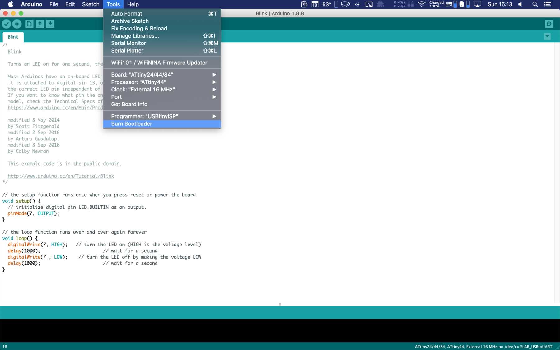
All I had to do was change the pin. But I only looked at my schematic drawing in Eagle and could then conclude on the PIN 7.
/*
  Blink

  Turns an LED on for one second, then off for one second, repeatedly.

  Most Arduinos have an on-board LED you can control. On the UNO, MEGA and ZERO
  it is attached to digital pin 13, on MKR1000 on pin 6. LED_BUILTIN is set to
  the correct LED pin independent of which board is used.
  If you want to know what pin the on-board LED is connected to on your Arduino
  model, check the Technical Specs of your board at:
  https://www.arduino.cc/en/Main/Products

  modified 8 May 2014
  by Scott Fitzgerald
  modified 2 Sep 2016
  by Arturo Guadalupi
  modified 8 Sep 2016
  by Colby Newman

  This example code is in the public domain.

  http://www.arduino.cc/en/Tutorial/Blink
*/

// the setup function runs once when you press reset or power the board
void setup() {
  // initialize digital pin LED_BUILTIN as an output.
  pinMode(7, OUTPUT);
}

// the loop function runs over and over again forever
void loop() {
  digitalWrite(7, HIGH);   // turn the LED on (HIGH is the voltage level)
  delay(1000);                       // wait for a second
  digitalWrite(7 , LOW);    // turn the LED off by making the voltage LOW
  delay(1000);                       // wait for a second
}
The board was still connected via the SPI programmer and the bootloader was burned using the Arduino IDE. Via FTDI I uploaded the sketch above. Pin 7 corresponded to the LED. The video shows a wild blinking LED, each with a delay of 1000ms.
Programming with C
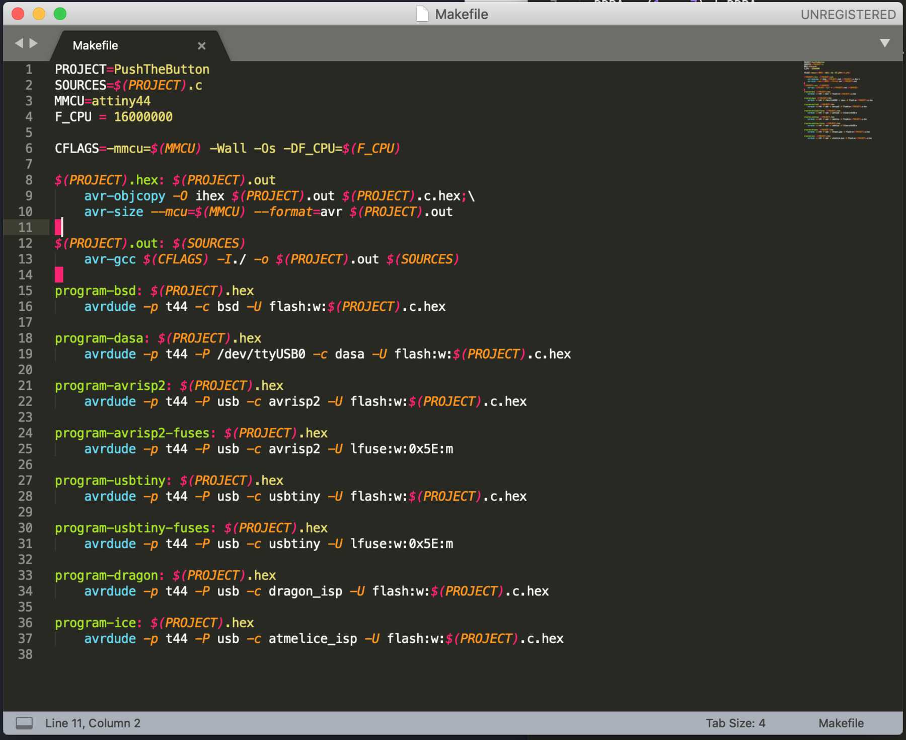
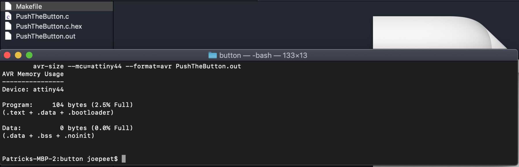
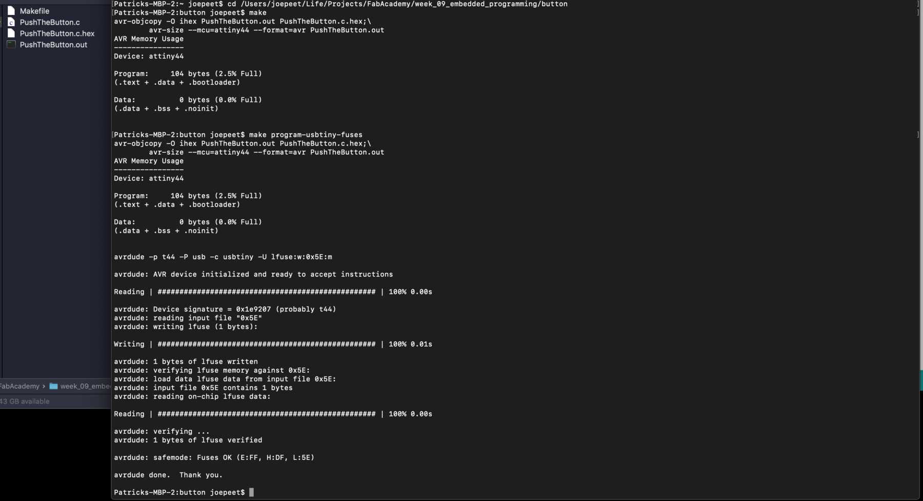
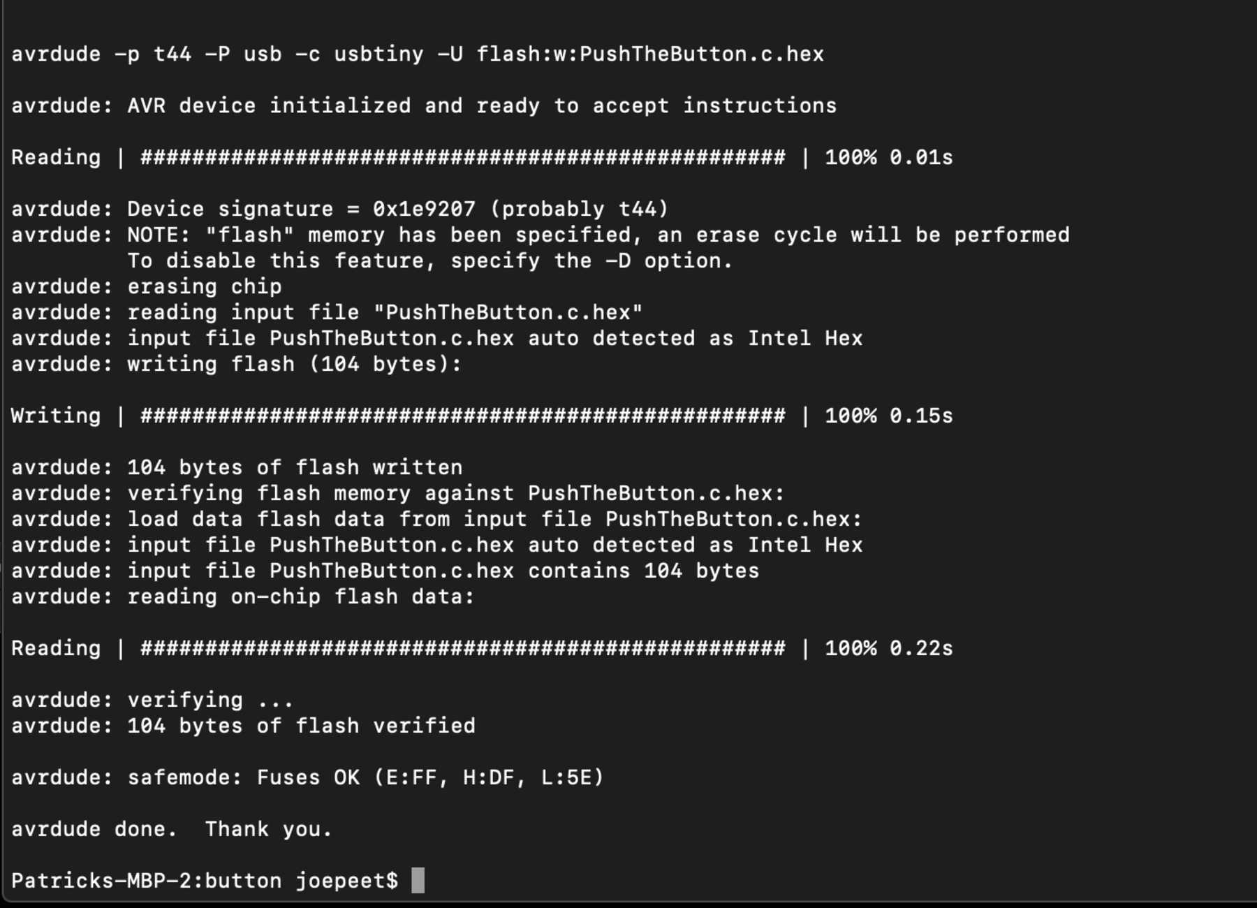
Next I wanted to choose the path of Neil, as in week 07. First I created a new file in Sublime Text, which then saved in PushTheButton.c. In this folder I also saved the Makefile from the previous assignment. First I adjusted the Makefile: Changed the project name and that was it. I opened the terminal and used the commands from the week 07 only for a different project.
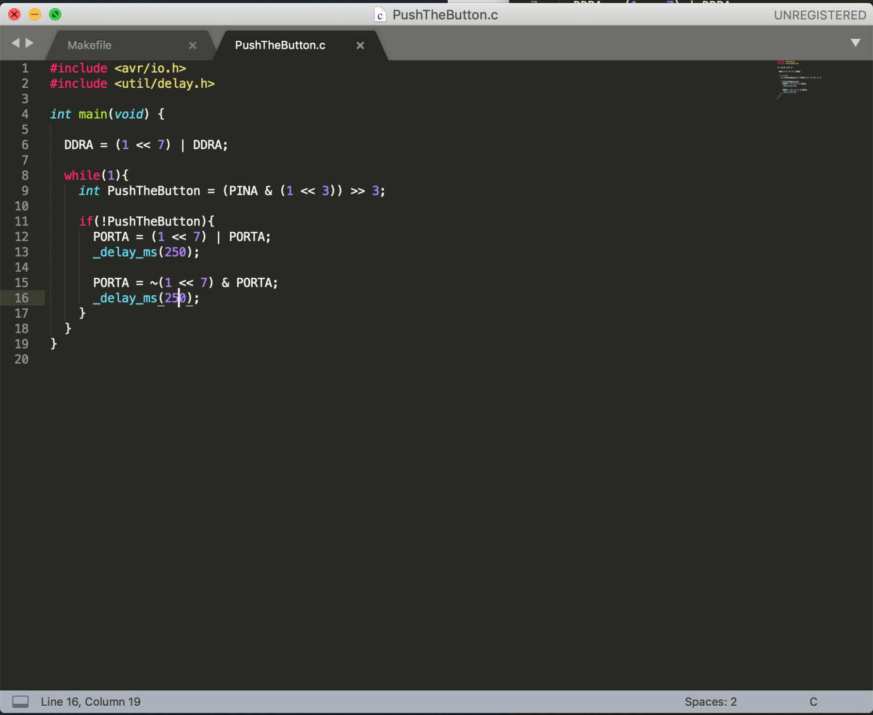
#include <avr/io.h>
#include <util/delay.h>

int main(void) {

  DDRA = (1 << 7) | DDRA;

  while(1){
    int PushTheButton = (PINA & (1 << 3)) >> 3;

    if(!PushTheButton){
      PORTA = (1 << 7) | PORTA;
      _delay_ms(250);

      PORTA = ~(1 << 7) & PORTA;
      _delay_ms(250);
    }
  }
}
Here a picture how I connected everything.
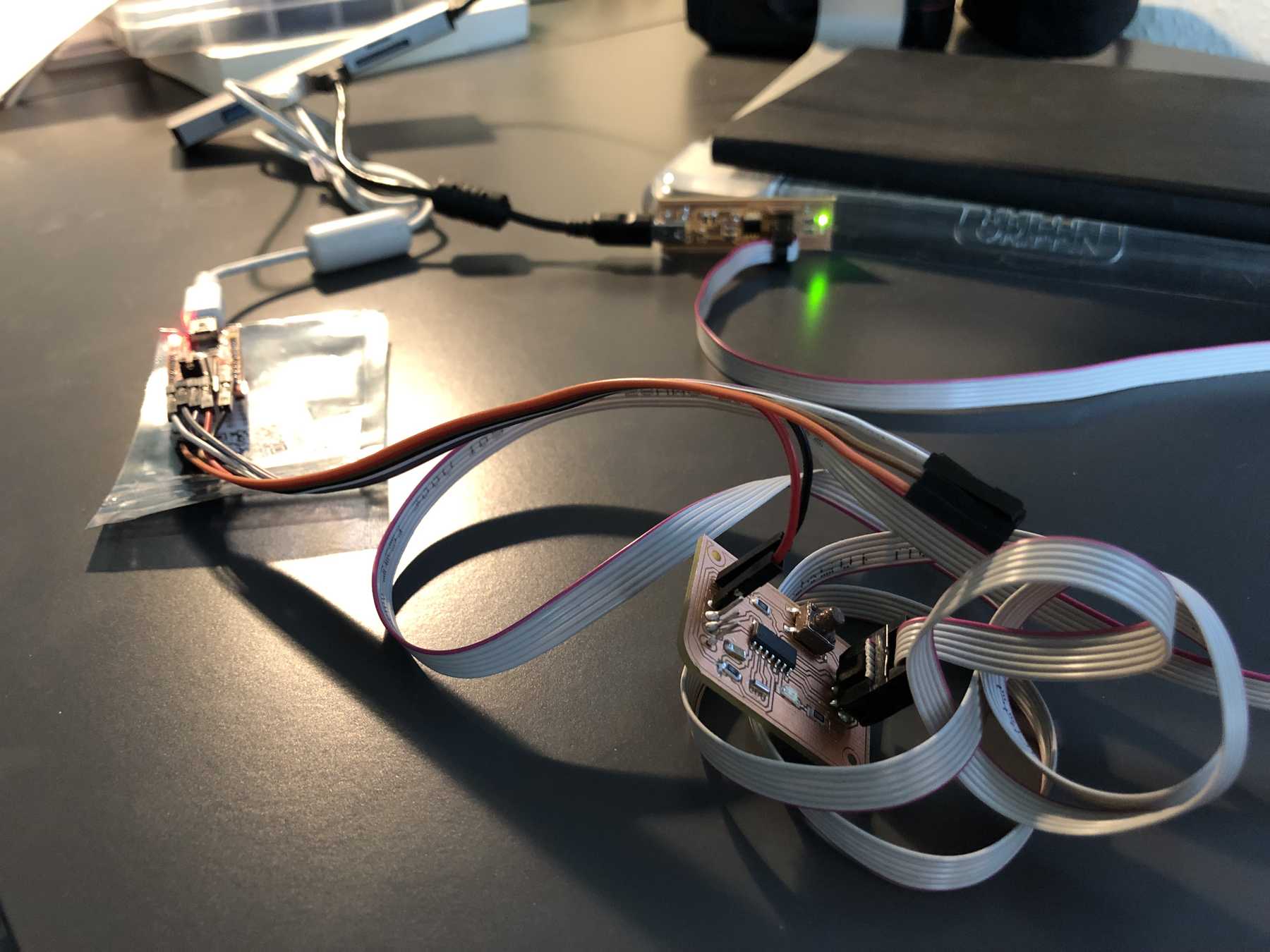
At the end a video how it worked and a small test of the “push the button”-test.
Group assignment
Overview of architectures
In the beginning I wanted to explain the different architectures and focus on understanding what the differences are between AVR and ARM. What is Harvard architecture, Neumann architecture, CISC or RISC? What workflows do they have, what kind of software do you use and what are the respective restrictions? For this I found a detailed paper online, which shows additionally all the workflows. They are now on my reading stack for the year.
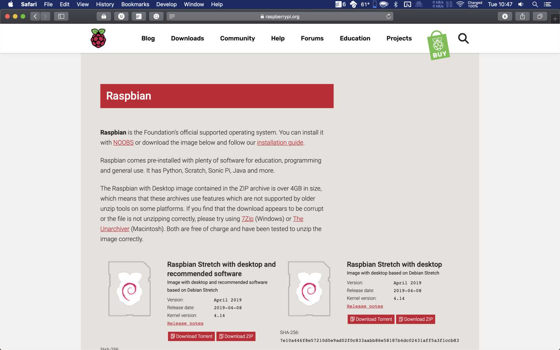
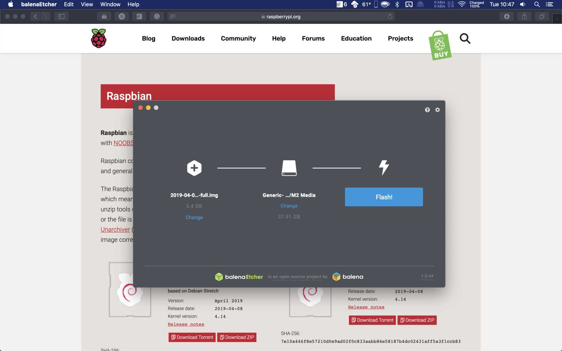
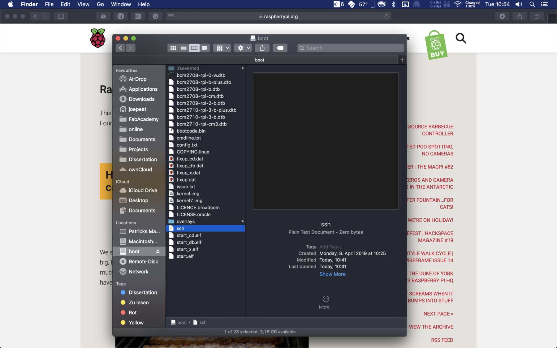
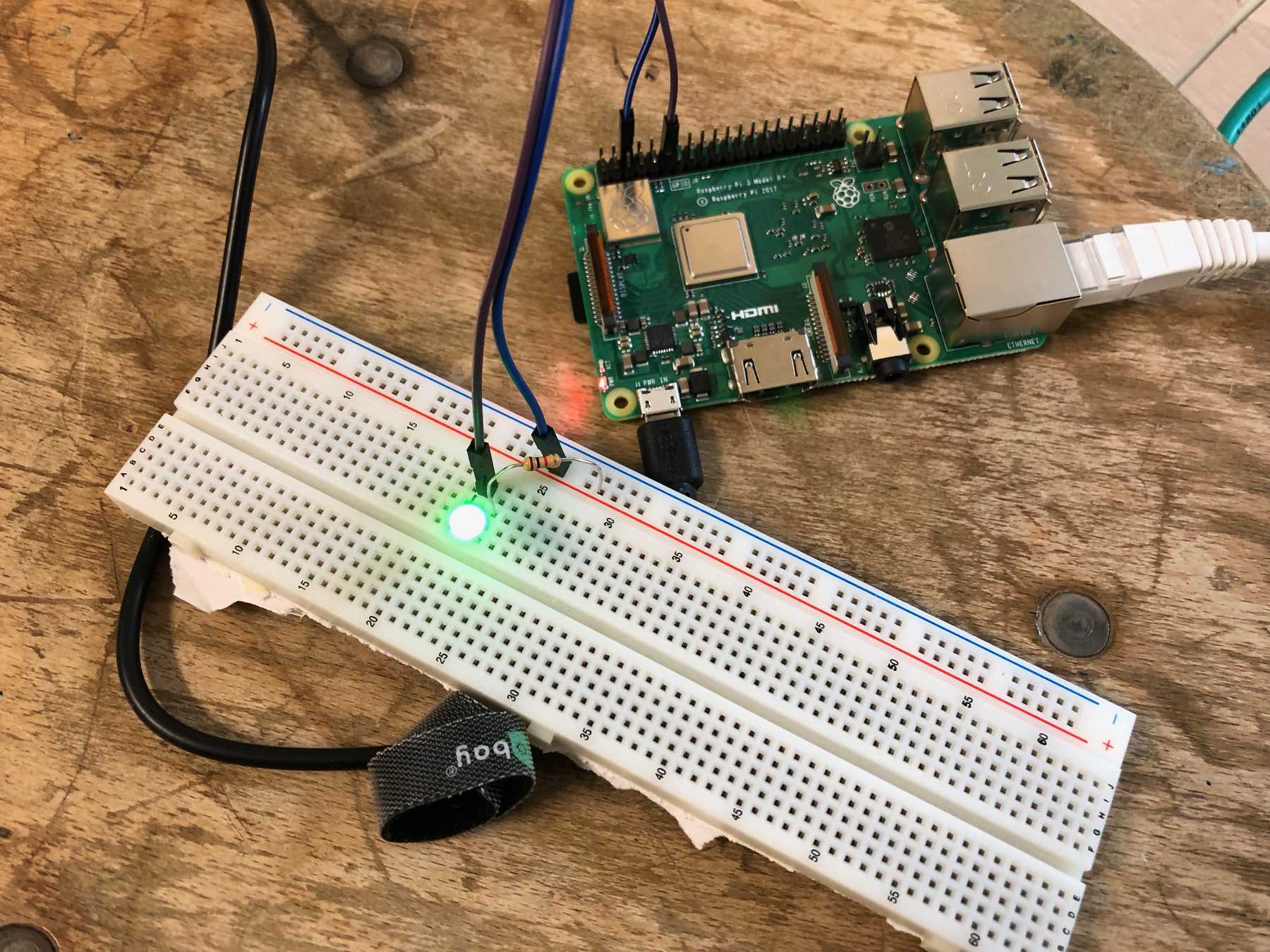
In my group assigment I wanted to look at the workflow for the Raspberry Pi. First I downloaded the current Raspbian image from the website RaspberryPi.org and then I used the etcher application to transfer the image from Mac to SD cards. To enable SSH it is enough to place a file named ssh without extension on the SD card.
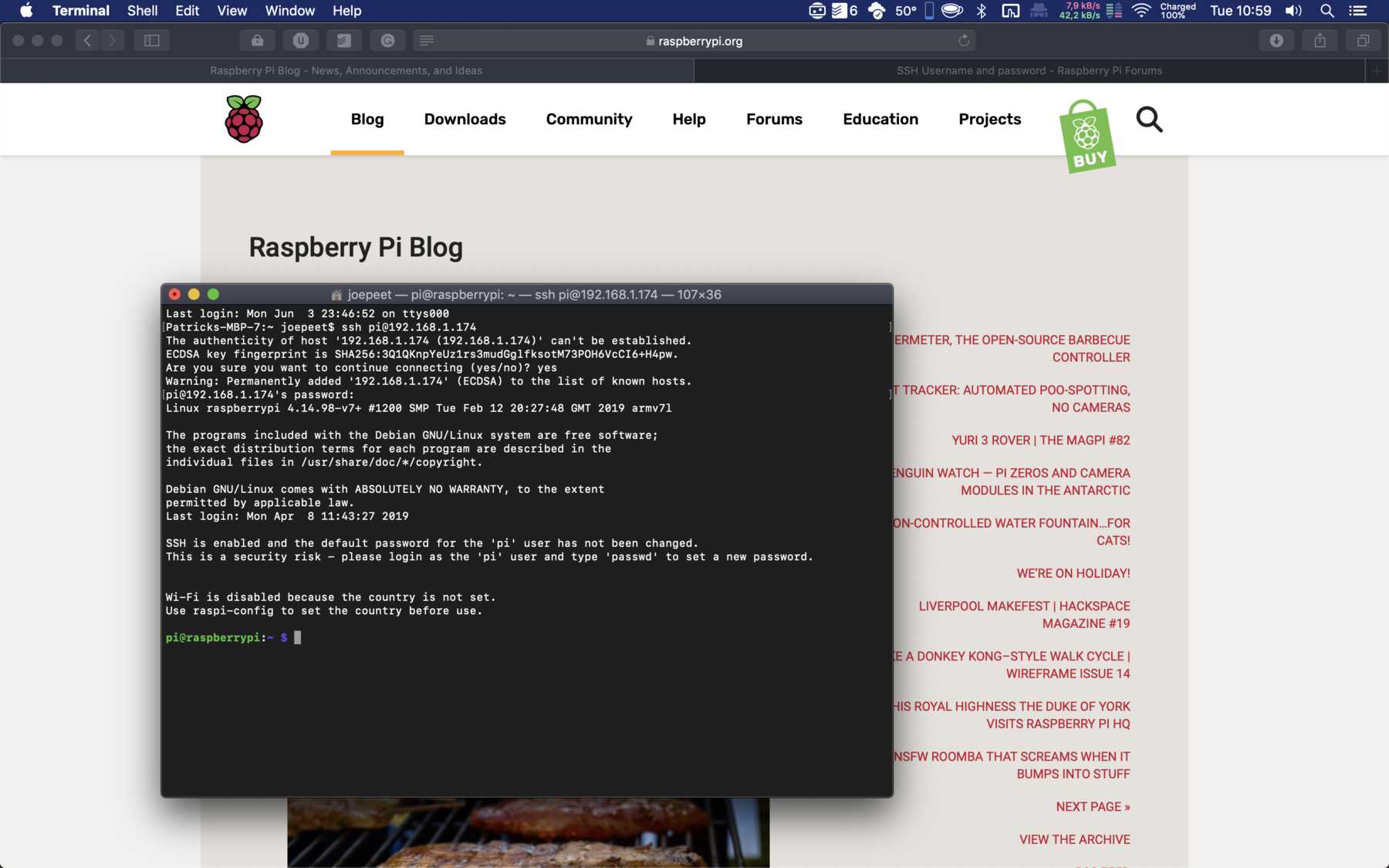
Next, we can connect the Pi to a network and connect to SSH. The IP address must be found out beforehand. I always use tools like Network Radar. Then we open the terminal and connect with the username pi and password raspberry.
ssh pi@X.X.X.X
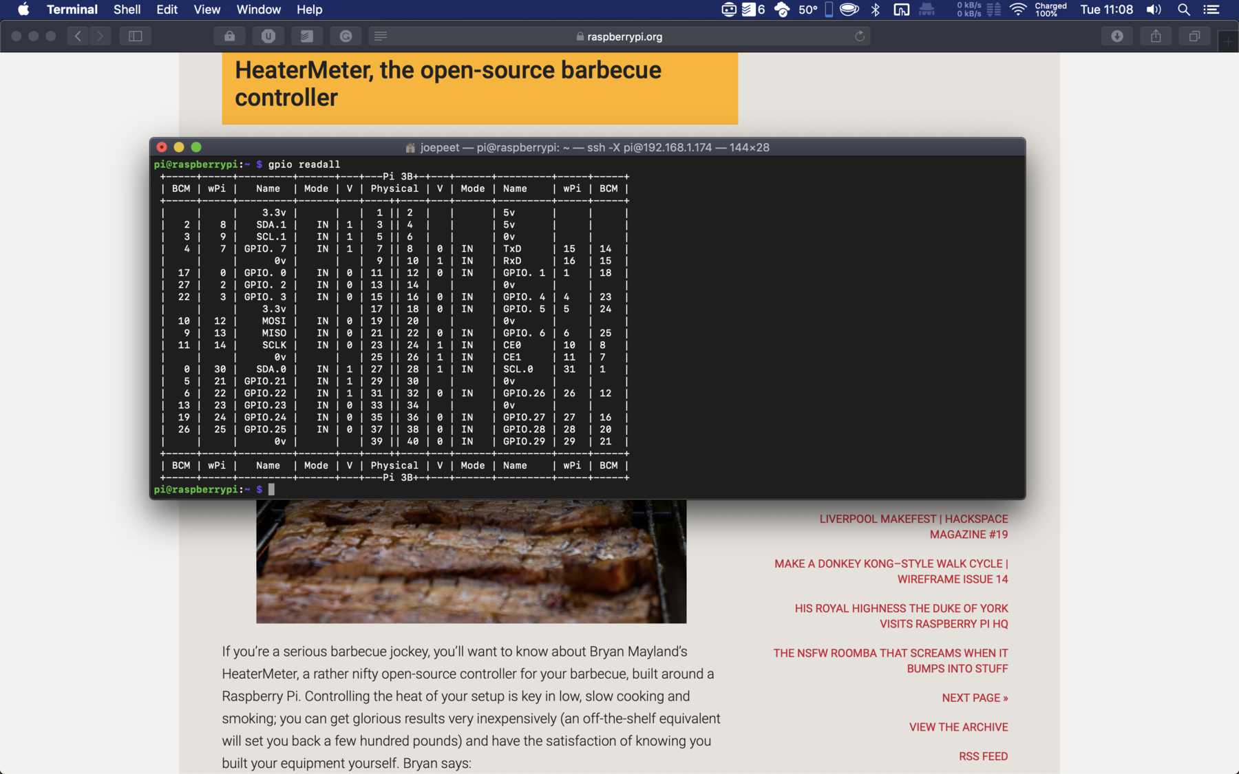
sudo apt-get install wiringpi
With gpio readall you can see the pinout. The next step is to create a blin.sh file and then edit it.
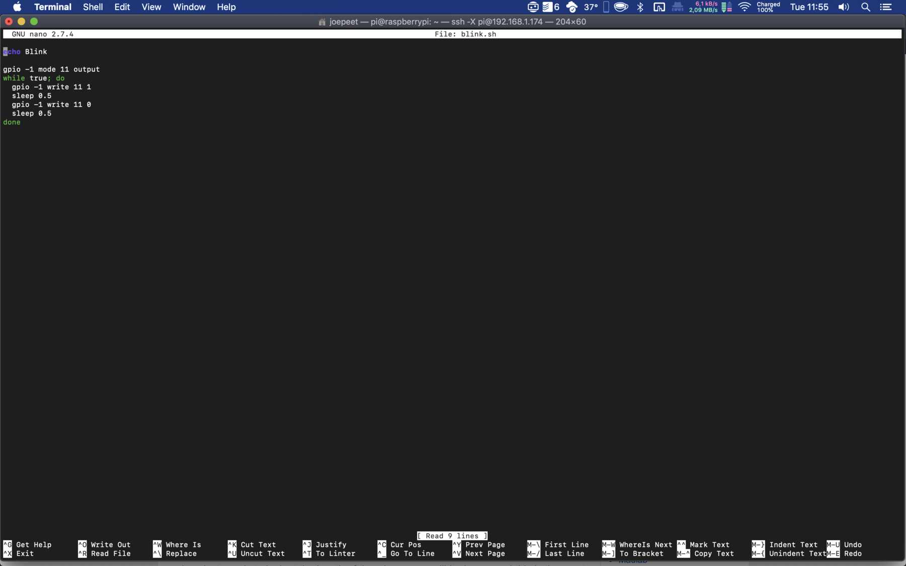
nano blink.sh
Now I have imported the code from the tutorial of drogon.net.
echo Blink

gpio -1 mode 11 output
while true; do
  gpio -1 write 11 1
  sleep 0.5
  gpio -1 write 11 0
  sleep 0.5
done
I started the script and watch the LED blink.
sh blink.sh
On the Raspberry Pi you can also use python in combination with GPIO. Countless tutorials can be found on the internet on sites like hackster.io, instructables, etc..
Here you can download the modified code for the PushTheButton-test:
PushTheButton-test