Electronics Design
Week 07
The electronics design week included several assignments. On the one hand, we had to explore our test equipment in our lab to observe the operations of a microcontroller circuit board as a group assignment. On the other hand, I was supposed to redraw the echo hello-world board, add a button and LED (with a current-limiting resistor), check the design rules, make it, and test it.
Group assignment
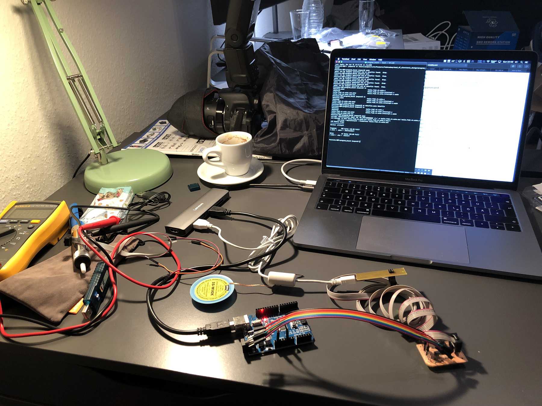
Explore your test equipment
There are two devices I can think of as test equipment. One is a multimeter and the other is an oscilloscope. As first example I take the multimeter, which with a very high chance can be found in every workshop. One can measure over different electrical quantities such as voltage, current strength and resistances. But also a continuity tester, a diode test and the measurement of capacitances is possible. At my hand I have a Fluke 115 multimeter.
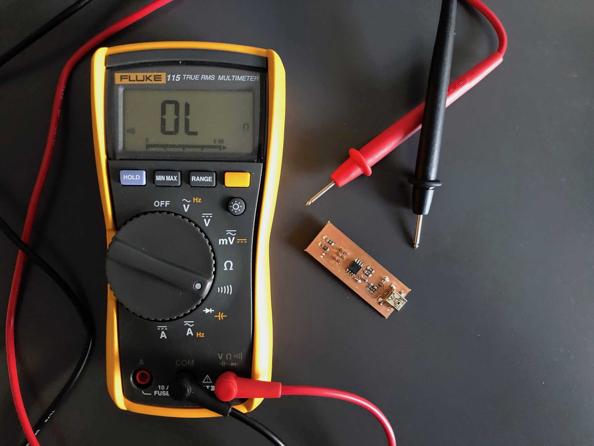
I use the continuity checker the most. Especially with the PCB-boards I followed every track meticulously, compared if nothing is connected to the ground. This can be done either via the digital display or via audio feedback. Most of the multimeters I see somewhere are from the Luke company, which I am completely enthusiastic about. Actually, they shouldn’t be missing in any workshop.
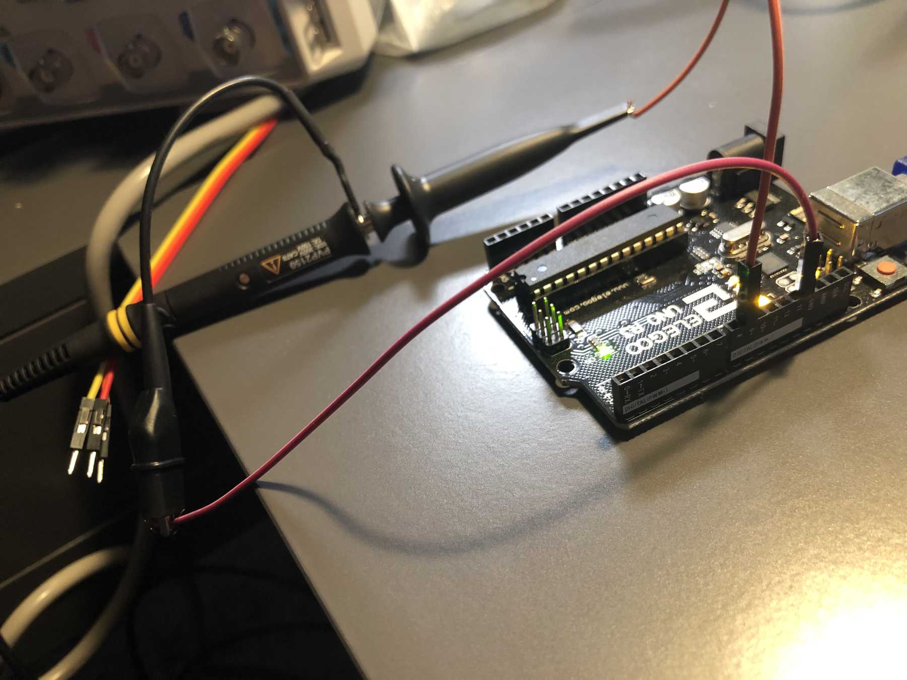
Next I used the oscilloscope - in my case a RIGOL DS1054Z. For this I took an Arduino and quickly found something to control a servo. The signal generated for this can’t be output by a multimeter, except as a number. In this and other cases, an oscilloscope is used to visualize voltages in the realtime range and to display and measure the time characteristics of physical quantities when using corresponding converters.
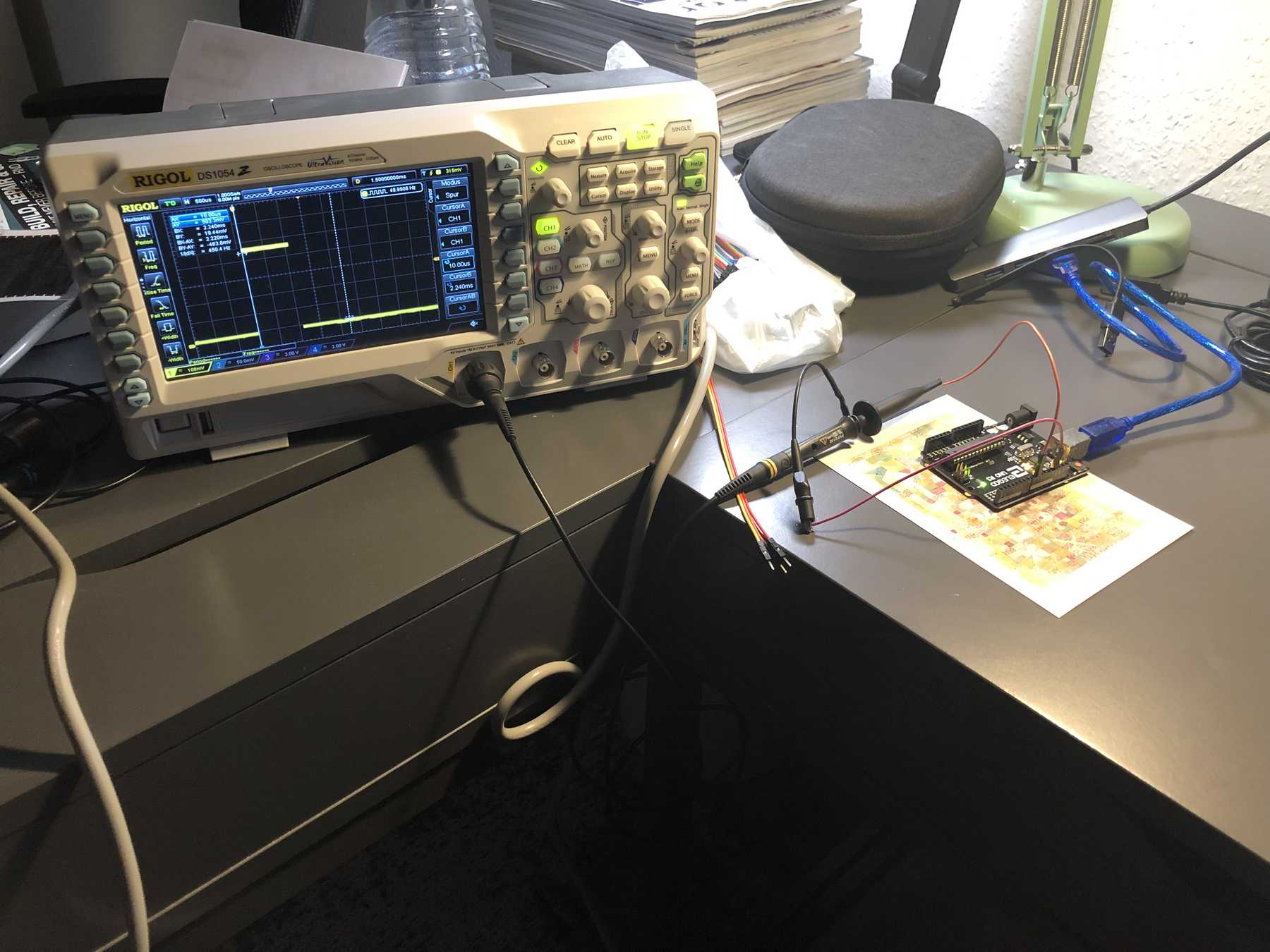
In the past there were electron beam oscilloscopes, which you know from many nostalgic movies and which you still love because of their look. Nevertheless, digital storage oscilloscopes (DSO) have rapidly gained in importance. With the help of a microcontroller it is possible to measure amplitudes and time differences as well as frequency and phase shift. In a later assignment I was able to find out again which frequency my resonator on my board oscillates with thanks to the oscillator.

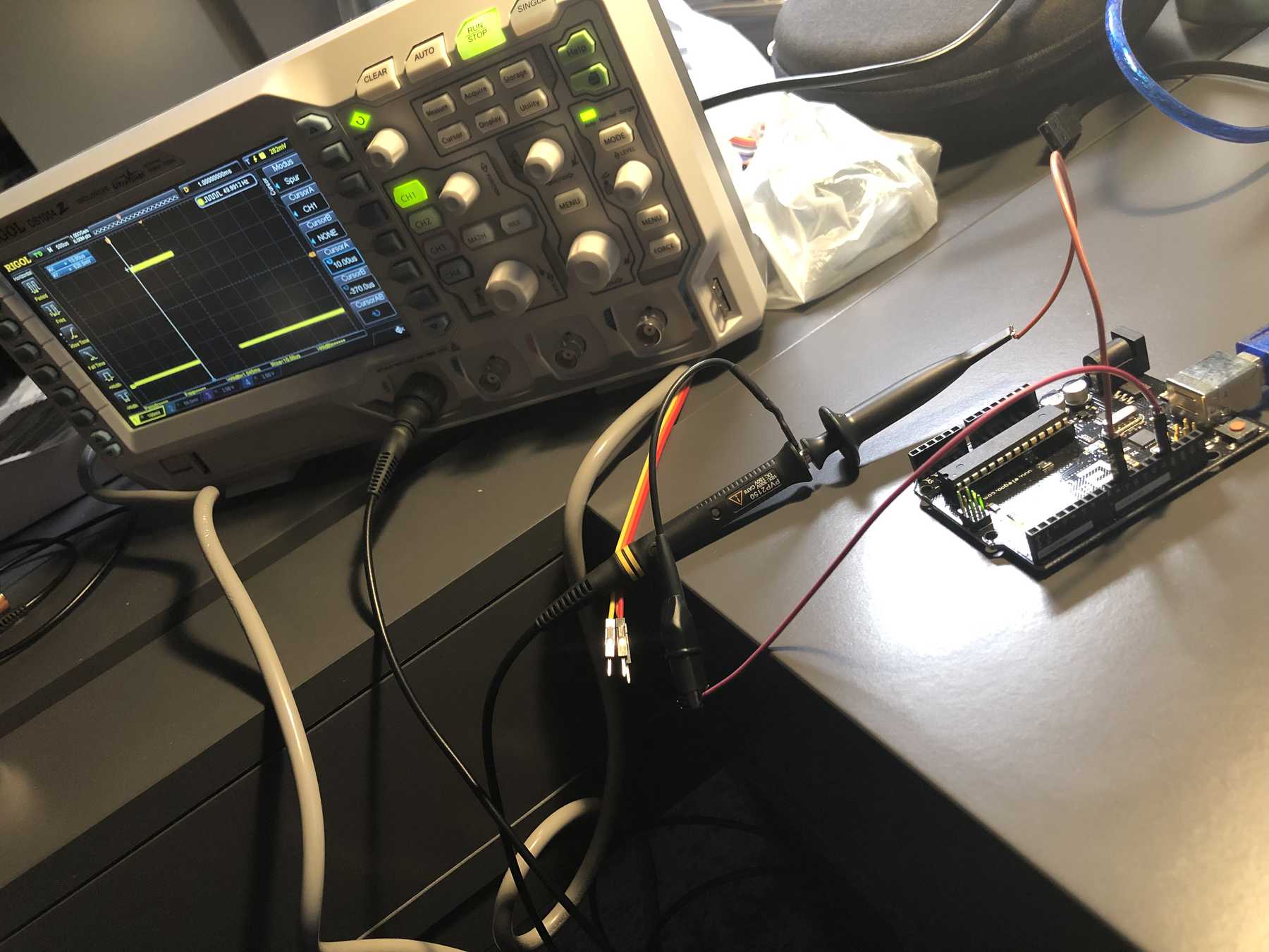
Back to Arduino: In addition to the visualization of periodic signals, it is also possible to display rectangular pulse sequences with different duty cycles. This has been done here, for example, where you can track the square wave pulse sequences for a control from a microcontroller.
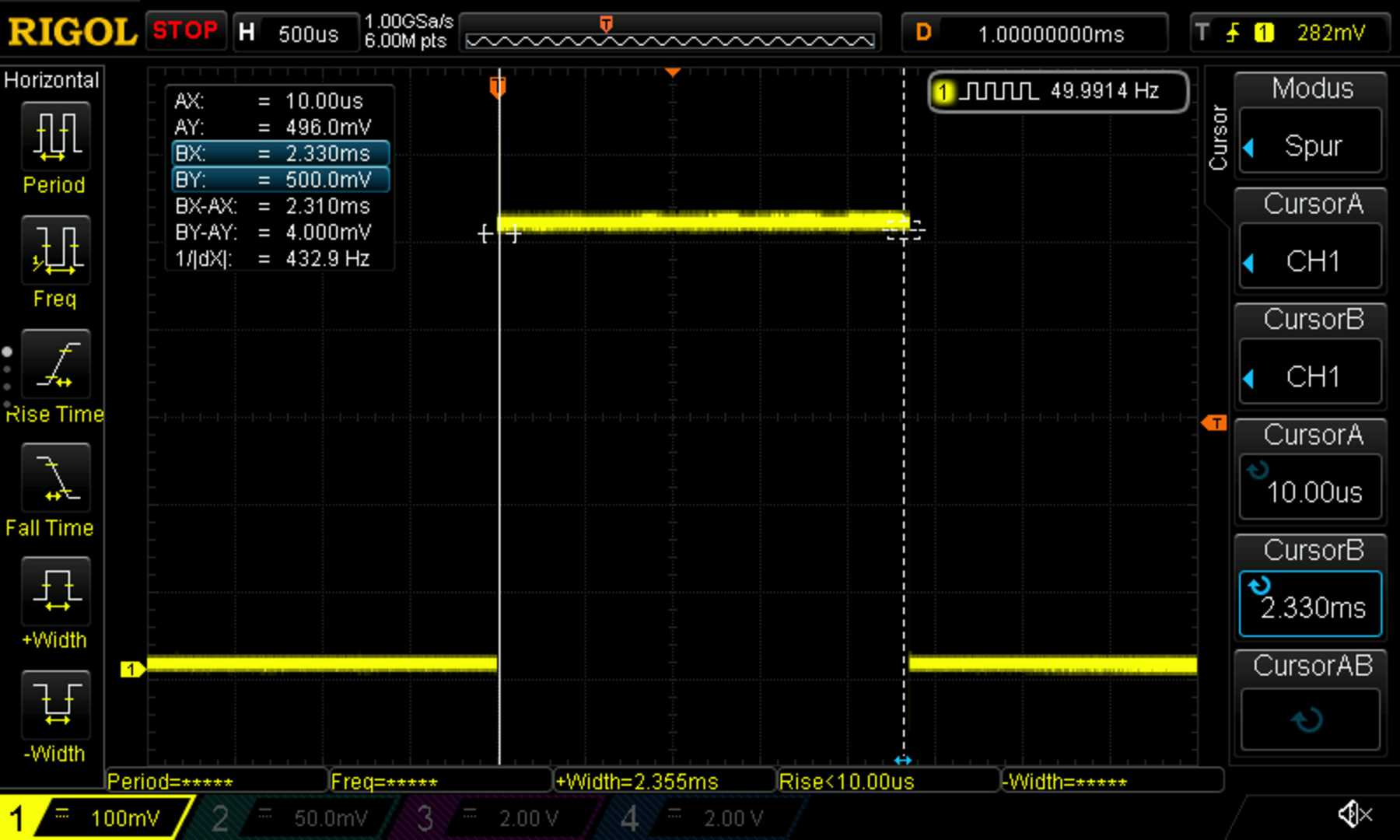
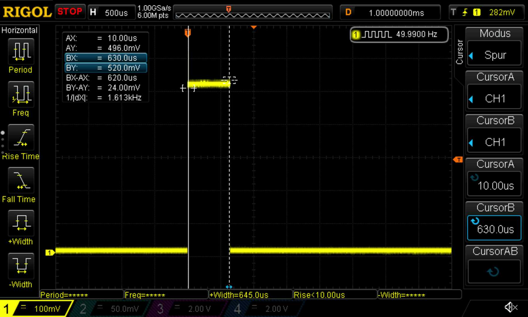
Depending on the pulse duration, different servo positions are addressed - from the minimum position to the maximum position. In the middle is the angle of 90°, at the beginning 0° and at the end with the longest pulse duration the maximum, which leads to 180°. The Arduino Code was the following:
#include <Servo.h>
Servo servo;
int reading;

void setup(void) {
Serial.begin(9600);
servo.attach(9); //servo at digital pin 9
servo.write(0); //initial point for servo
}

void loop(void) {
 reading = analogRead(A0); //attached to analog 0
 Serial.print("Sensor value = ");
 Serial.println(reading);

int value = map(reading, 0, 1023, 0, 255);
 servo.write(value);
 delay(100);
}
Individual assignment
Redraw the echo hello-world board
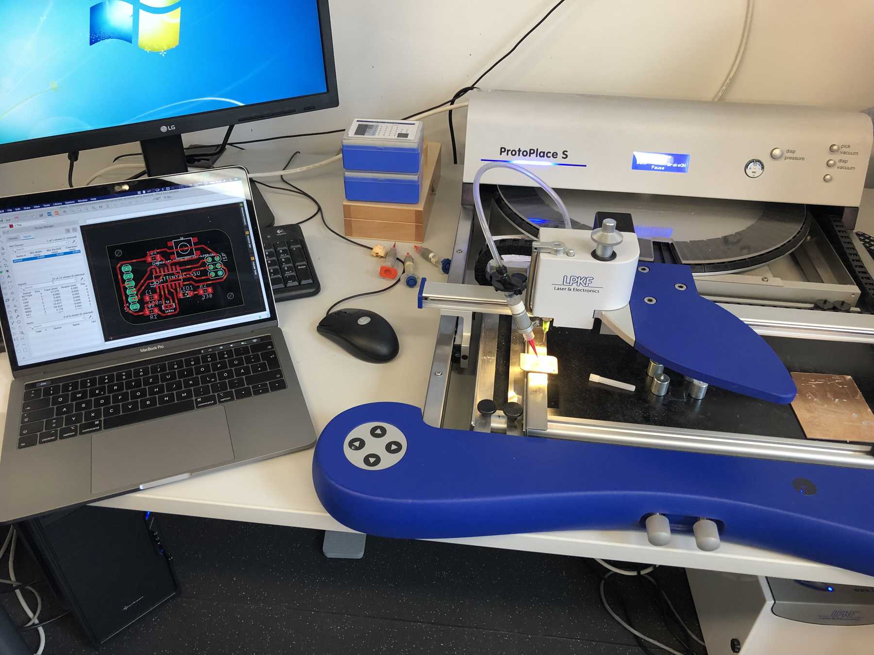
To design my hello-world board I used Autodesk EAGLE like in the week 05 - Electronics Production. More notes about PCB design rules and how to use the software can be found there. Also the handling of the CNC-PCB-machine from LPKF can be found on this page.
I used the tutorial from the fab academy documentation, where I found the schematic design template for the redrawn hello-world board. Also I read a lot of tutorials like from Sparkfun
Some EAGLE tips
- Via "Name" (naming function) in eagle schematics, you can directly add a name to a signal path and a label will be added.
- To create a 3D library, place the zero point in the library (bottom left, center, etc.) to align new 3D parts to the footprint more easily in Autodesk Fusion 360.
- If you want to share libraries within a team, you should load the libs, dru and co into the cloud (dropbox, drive) and link this folder or share it with others.
- Before autorouting is used, you should lay important lines manually and set the rules correctly. Then distances etc. are automatically kept during routing.
- Avoid direct 90° angles.
- Do not trust the component size in the data sheet if they are to be placed close to each other.
- The ground plane can also be used as a cooling surface. The effect of cooling properties becomes clear when soldering to ground pads.
- Often used designs should be saved as design blocks.
- If you want to drill the holes in PCBs in the classic way, there is the "drillaid" in ULP, which extends the drill holes.
- Never use the pcb file directly in Fusion to modulate it in Fusion360. If a surface of the eagle design is used as reference when drawing, eagle refuses the later sync with the fusion cloud. rather create a new document and insert the construction there and leave it linked.
- Watch out between US and DE character symbols.
- Use the page function for larger schematics and split it by function.
- Decoupling capacitors as close as possible to the supply pad (<4mm).
- The boarddesigner now displays the trace length directly in a window on the left. Useful for communication traces like SPI.
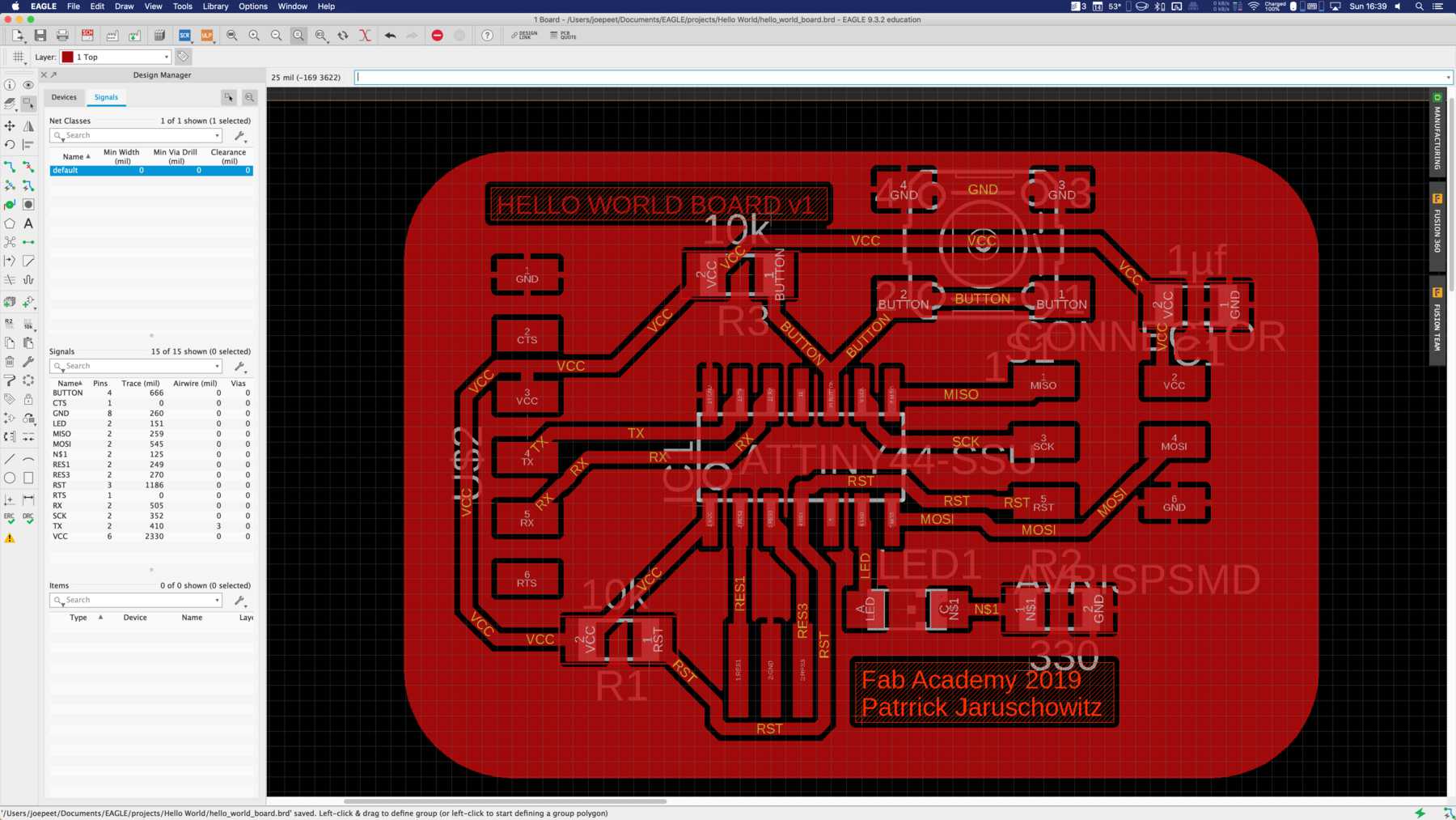
The first step was to trace the hello world board in Autodesk EAGLE. In the following you can see the development by the pictures. The files to download can be found at the bottom of this page.
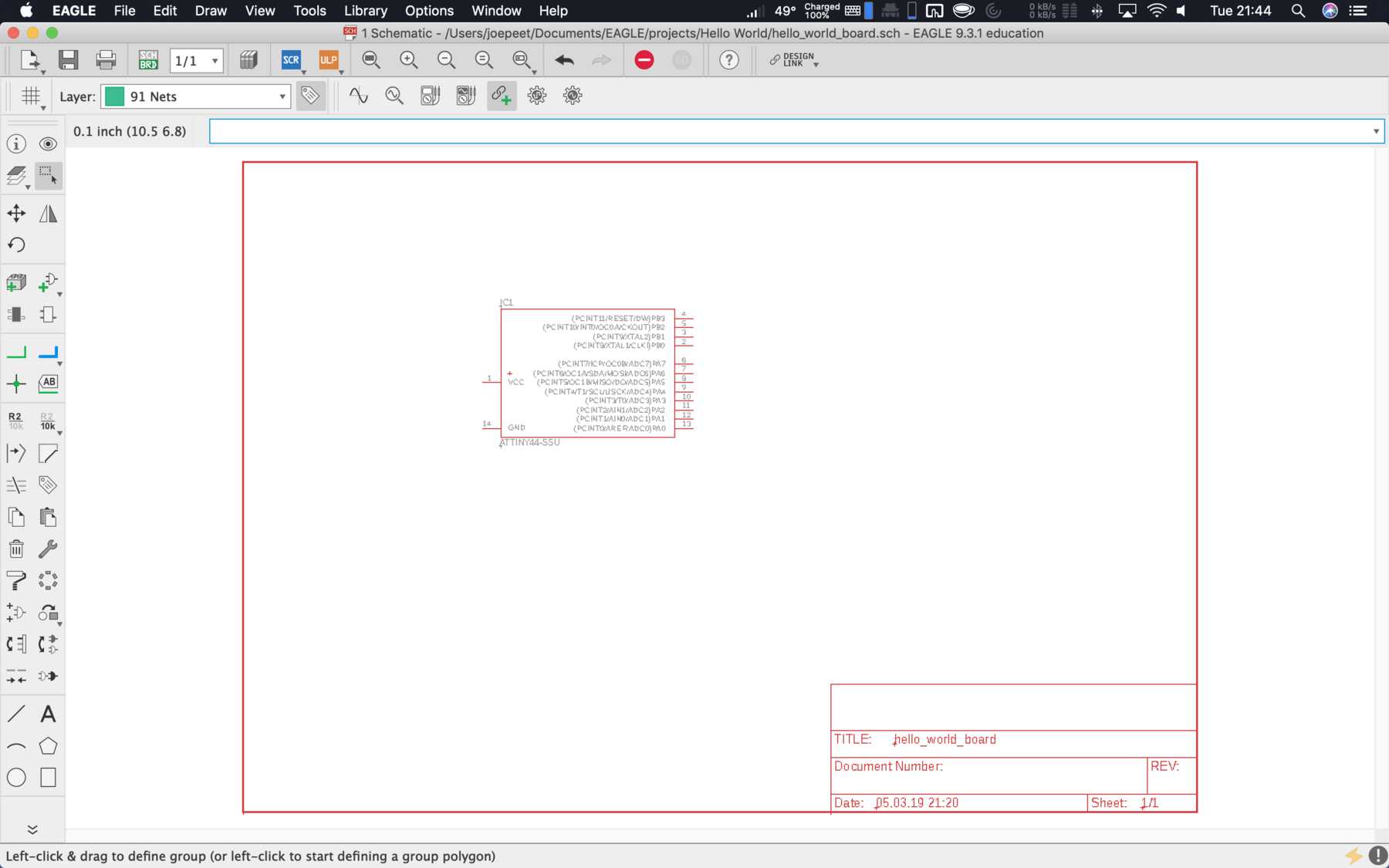
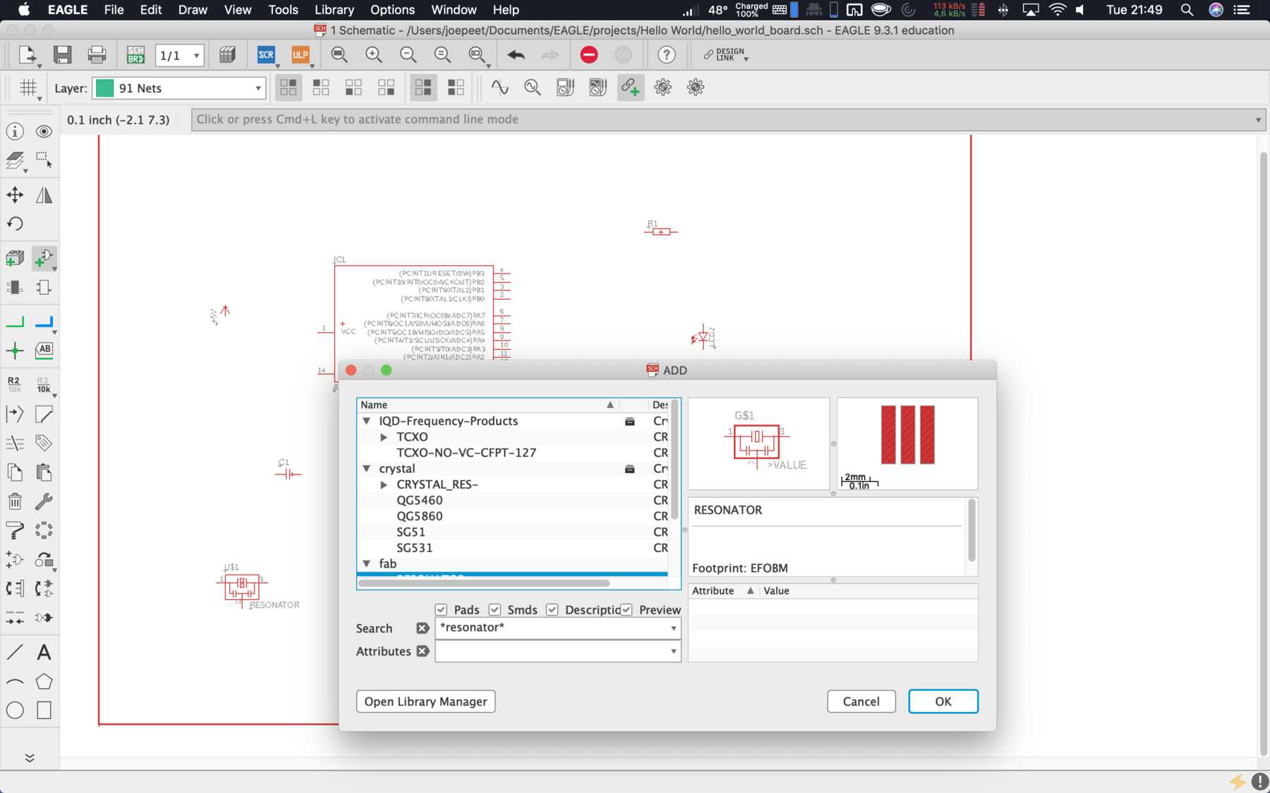
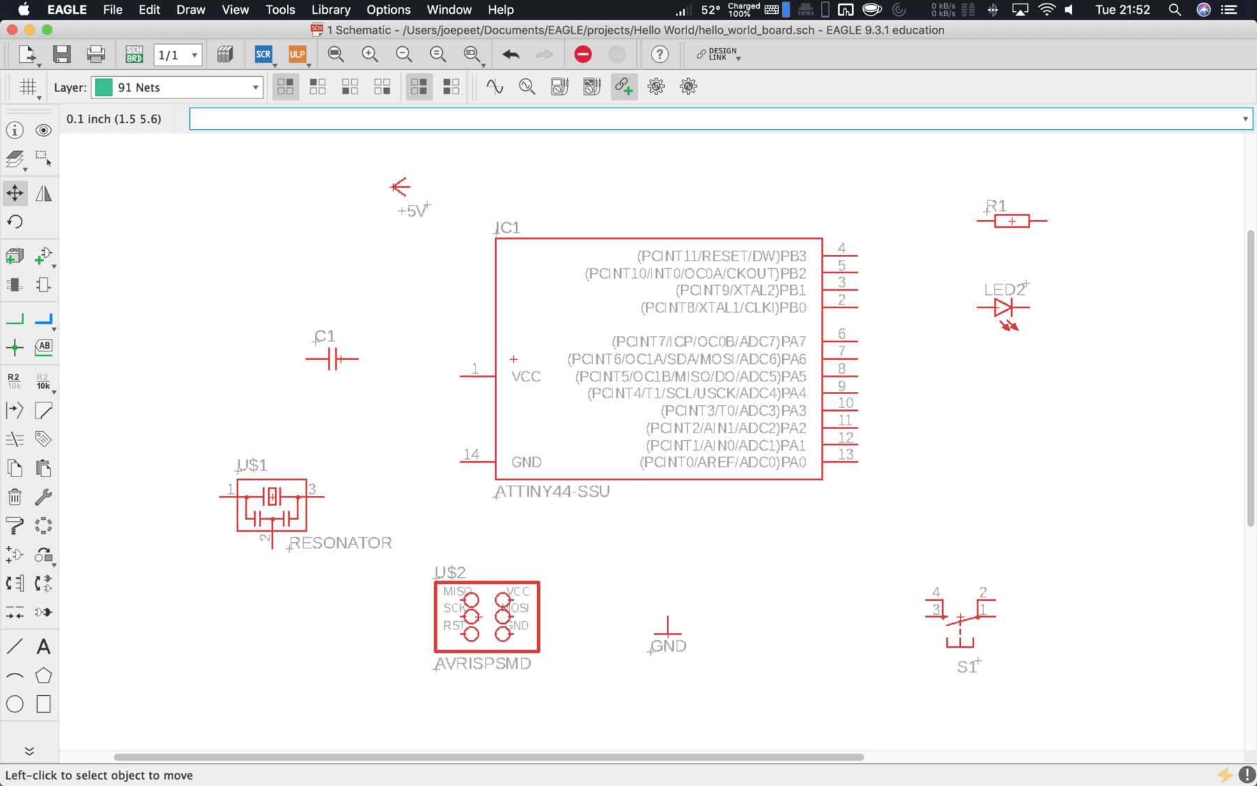
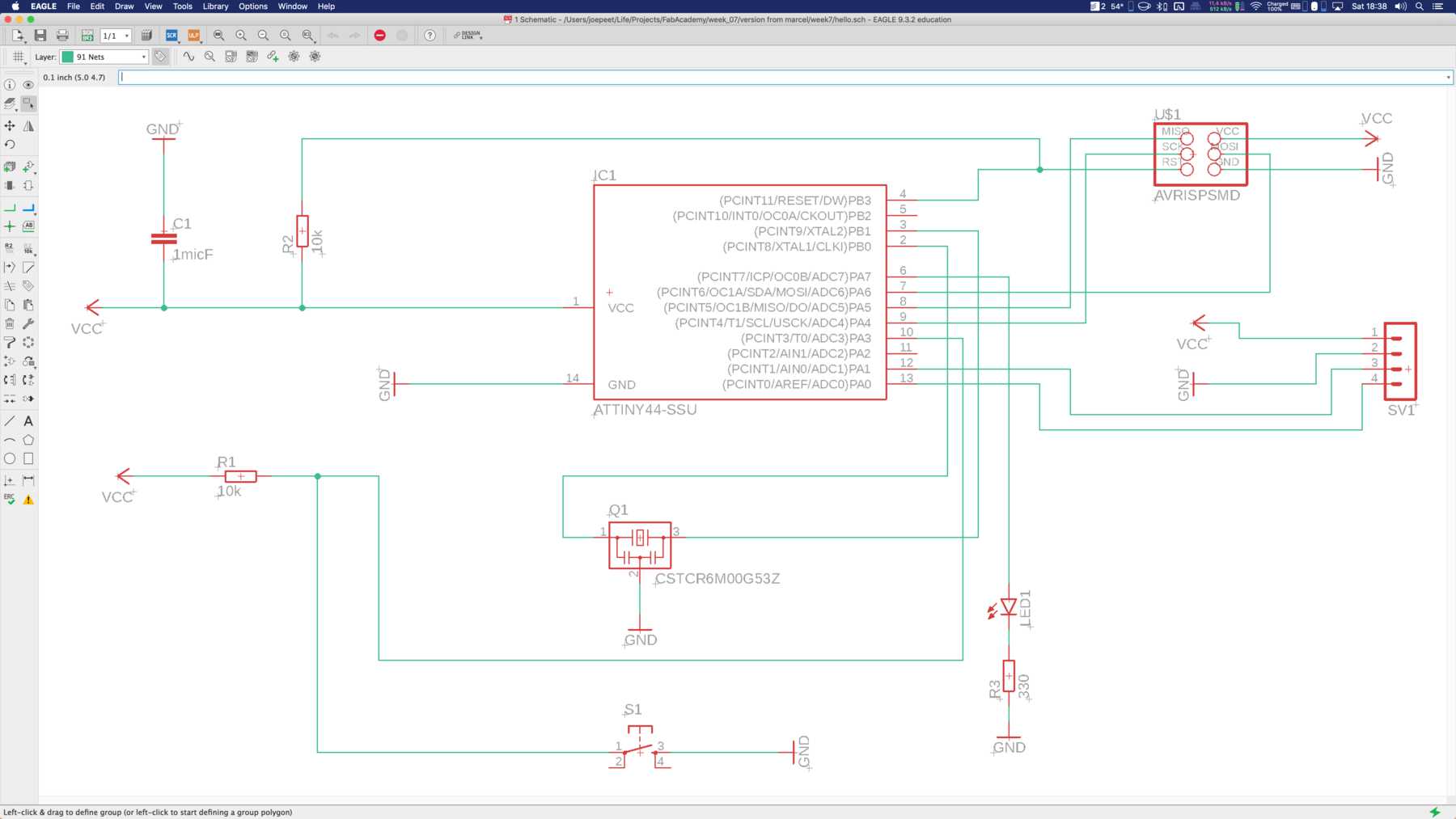
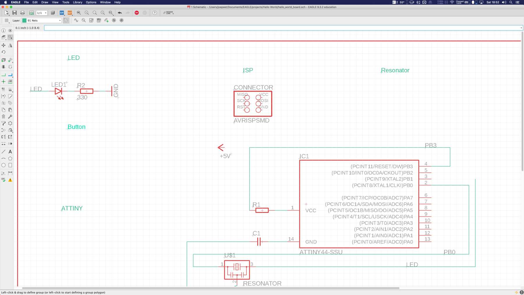
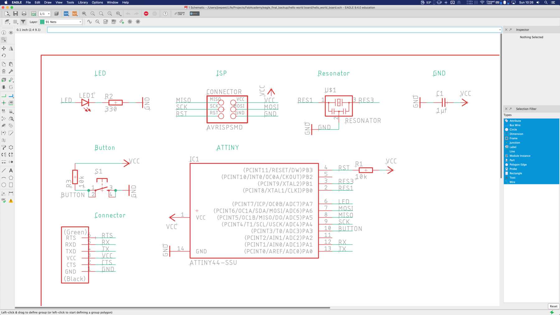
The schematic drawing was built step by step again. During the assignments I noticed several times: Check what parts are in stock. Then, and only really when you are sure that they are really these parts, include them in your drawing. Many parts weren’t there after all, so I tried to buy some SMD parts locally. This is a really difficult task, because the local selection is incredibly low. I wouldn’t invest the time I spent on it again. I praise mouser - very competitive prices and an incredibly quick shipping within two working days. Then everything was there. Unbelievable, for the fact that it is also an international shipment. Many other people do the same - either buy online at digikey, mouser or conrad. The shipping is calculated, but buying locally is not worth it, because many components are rare or only available in limited quantities. As well as with as many possible and different components as available online, it is also similar with the footprints of the individual components. There are just too many of them to have a footprint for everyone.
My final version included the following parts:
| Qty | Value | Device | Package | Parts | Description |
|---|---|---|---|---|---|
| 1 | LEDCHIPLED_1206 | CHIPLED_1206 | LED1 | LED | |
| 1 | PINHD-1X6 | 1X06 | JP1 | PIN HEADER | |
| 1 | PINHD-2X3 | 2X03 | ISP | PIN HEADER | |
| 1 | 100nF | CAP-UNPOLARIZED | C1206 | C1 | |
| 2 | 10k | R-EU_R1206 | R1206 | R1, R3 | RESISTOR, European symbol |
| 1 | 16MHz | RESONATOR-16MHZSMD_3.2X1.3 | RESONATOR-SMD-3.2X1.3 | Y1 | 16MHz Resonator |
| 1 | 330 | R-EU_R1206 | R1206 | R2 | RESISTOR, European symbol |
| 1 | ATTINY44-SSU | ATTINY44-SSU | SOIC14 | IC1 | |
| 1 | MOMENTARY-SWITCH-SPST-SMD-6.2MM-TALL | MOMENTARY-SWITCH-SPST-SMD-6.2MM-TALL | TACTILE_SWITCH_SMD_6.2MM_TALL | S1 | Momentary Switch (Pushbutton) - SPST |
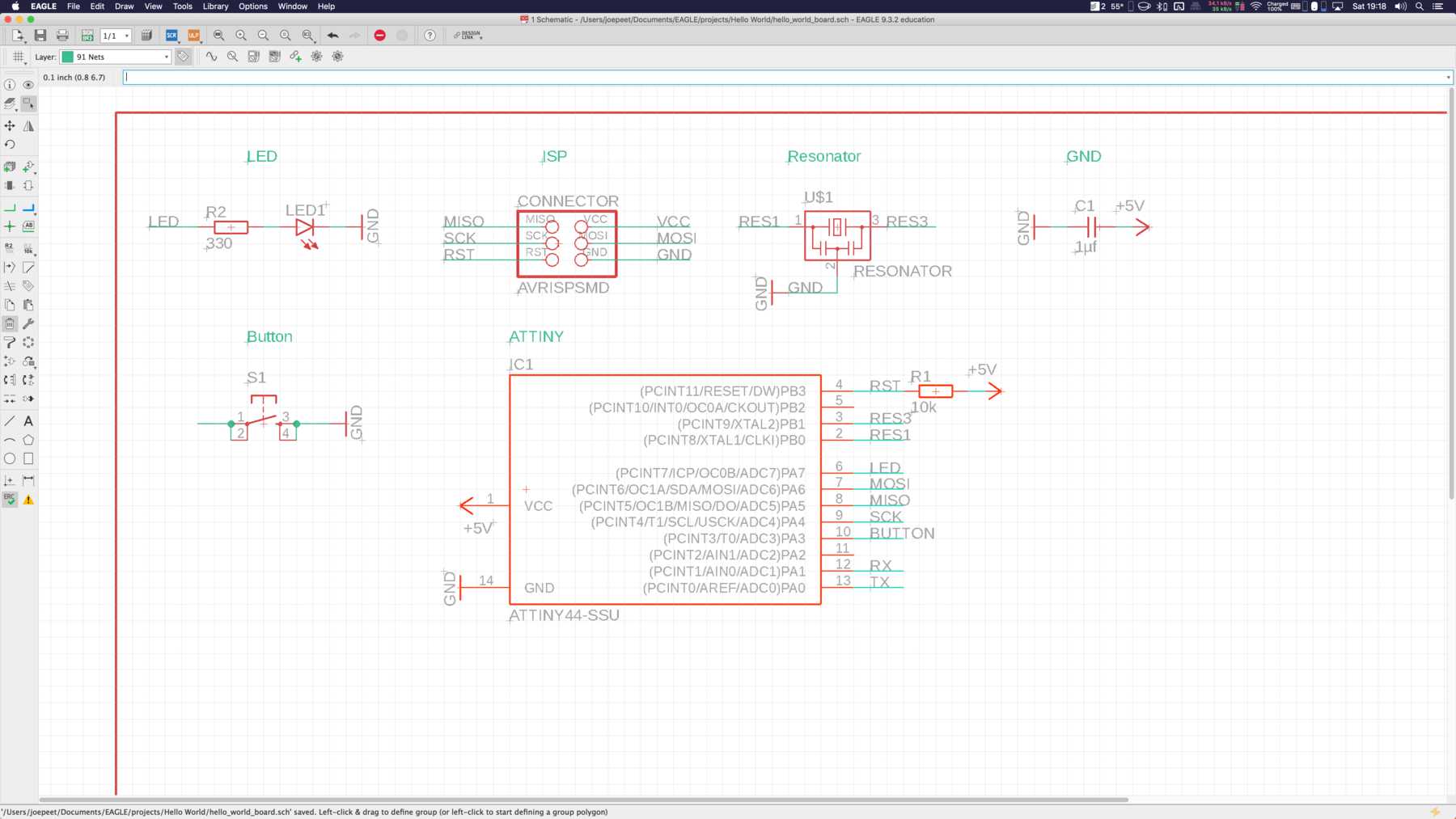
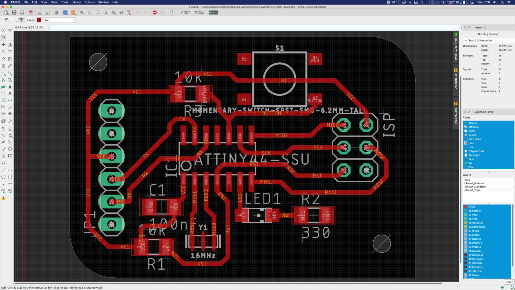
Finally I finished my board in the schematic drawing. I set the capacities to 100nF - so my schematic drawing looked like this at the end.
PCB production
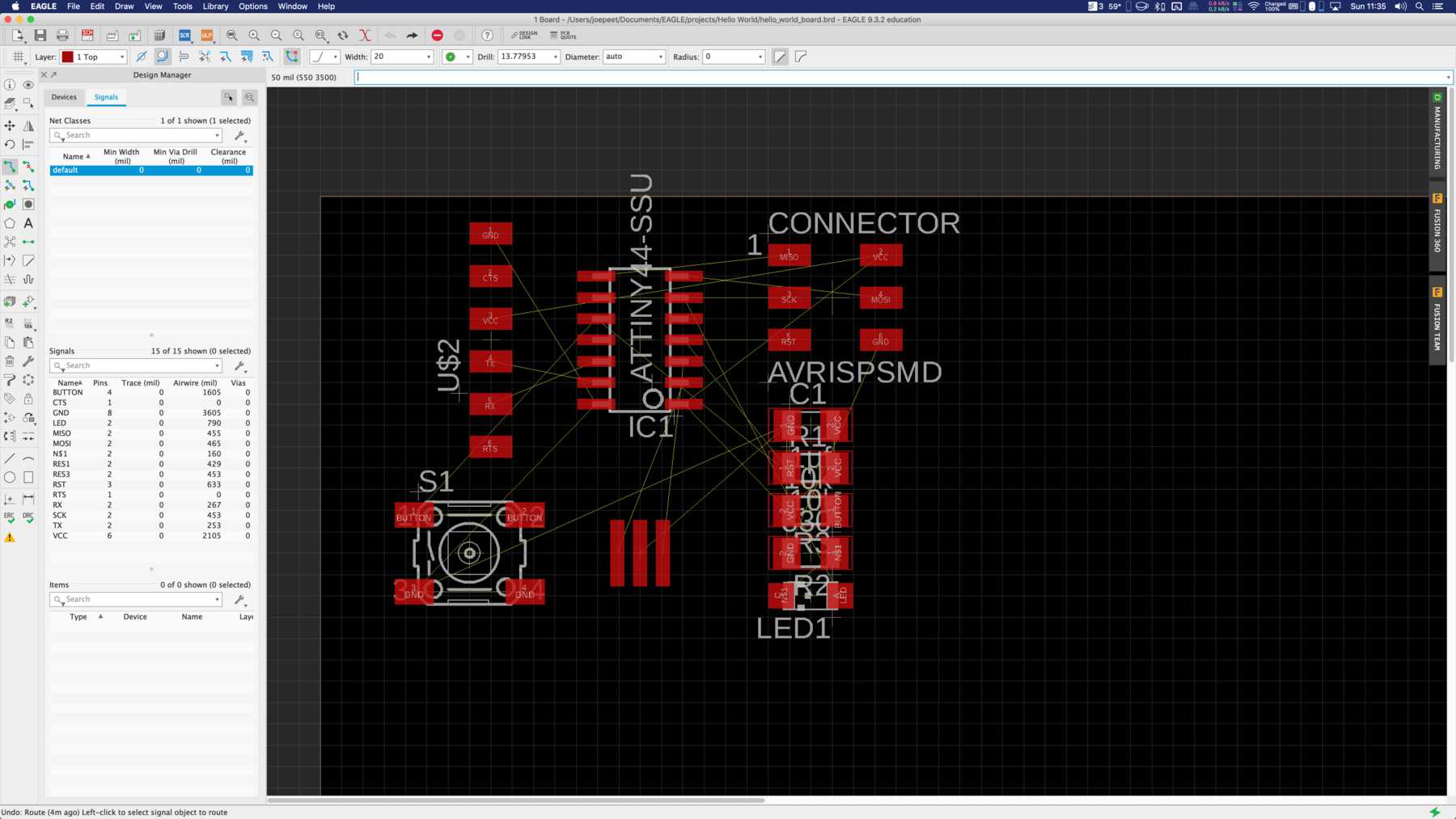
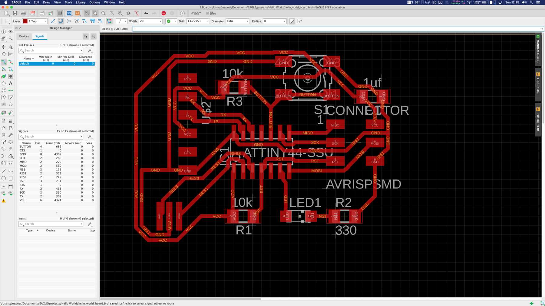
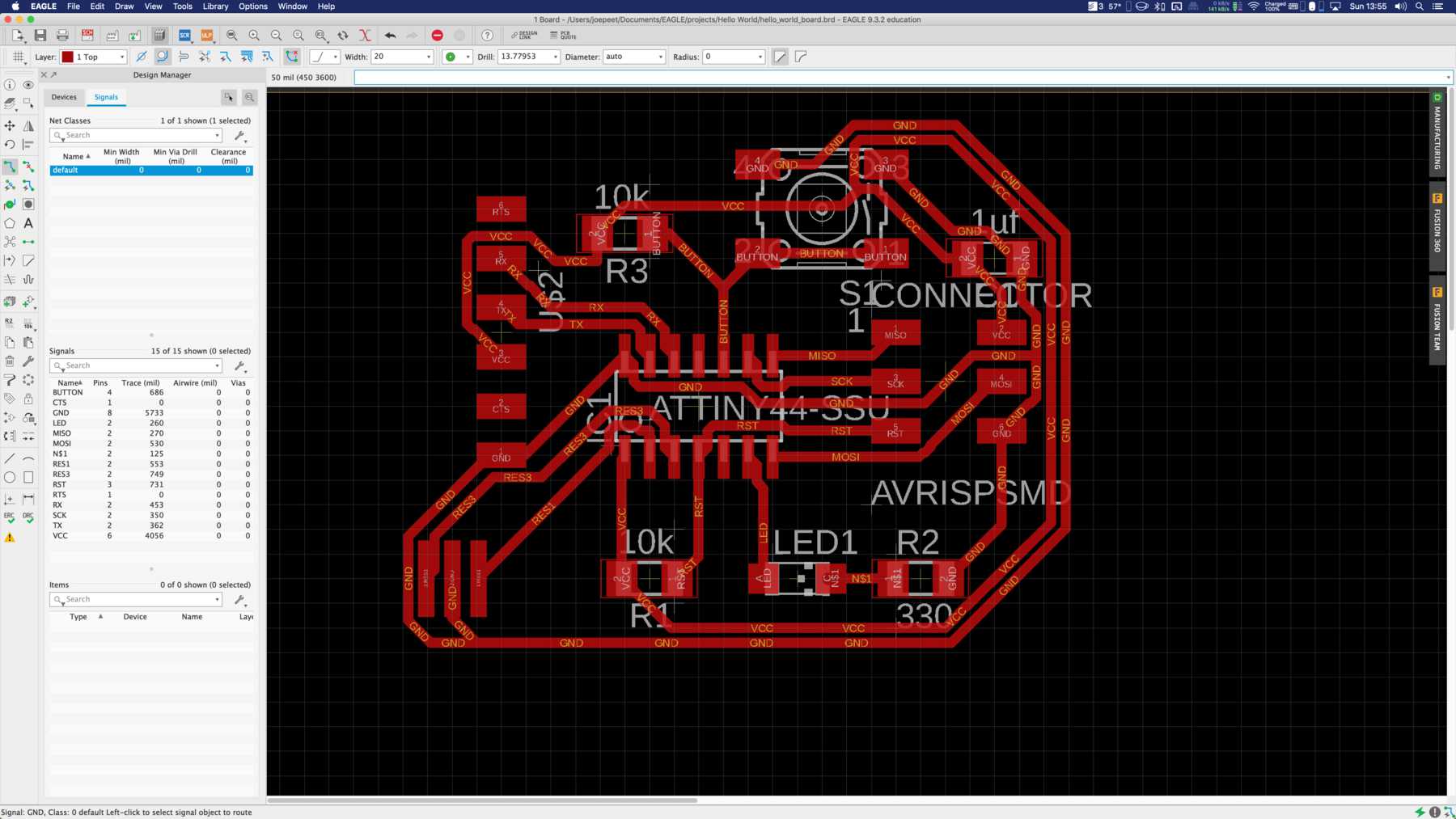
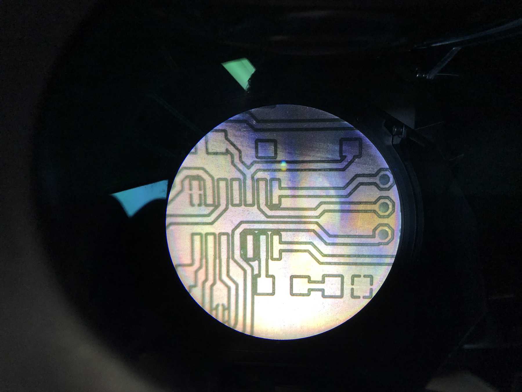
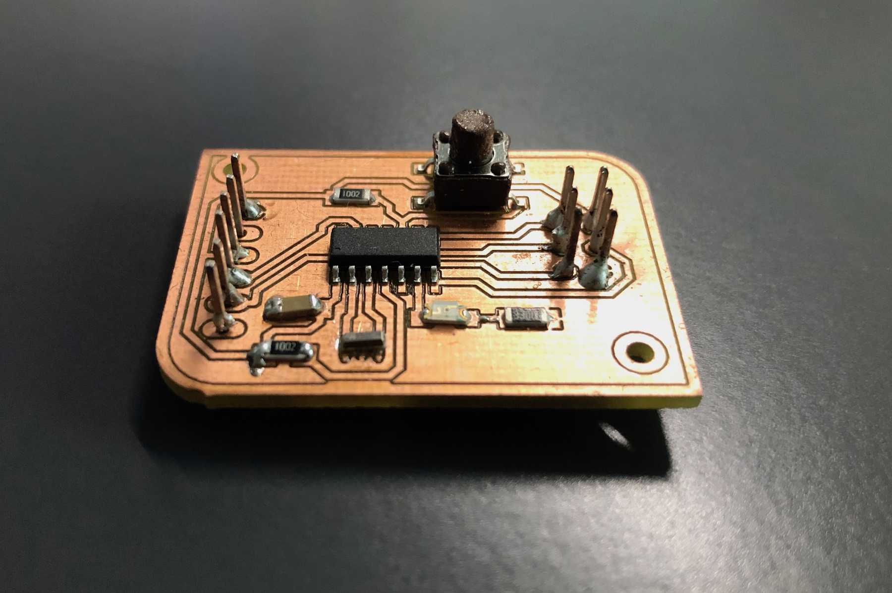
In week 05 the production of printed circuit boards was described. So I’m a little shorter here and don’t describe the whole process again. It was exciting, that small iterations, also at the design, were carried out for this board. So you can see a necessary and well thought out development of the different boards. In the end I wanted to have rounded corners, which make the whole thing more appealing. In the end I did everything with the LPKF ProtoMat S63 and soldered it.
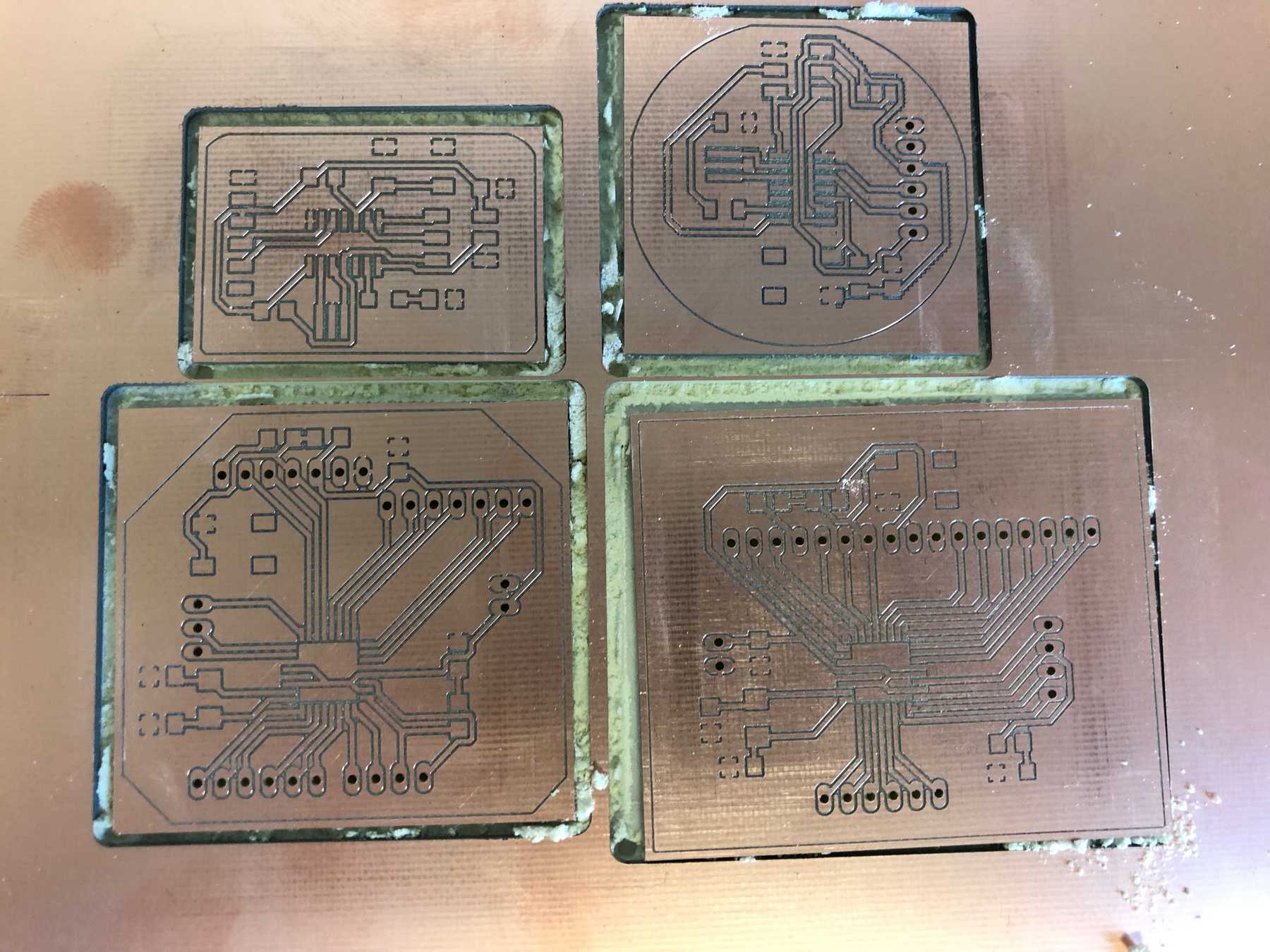
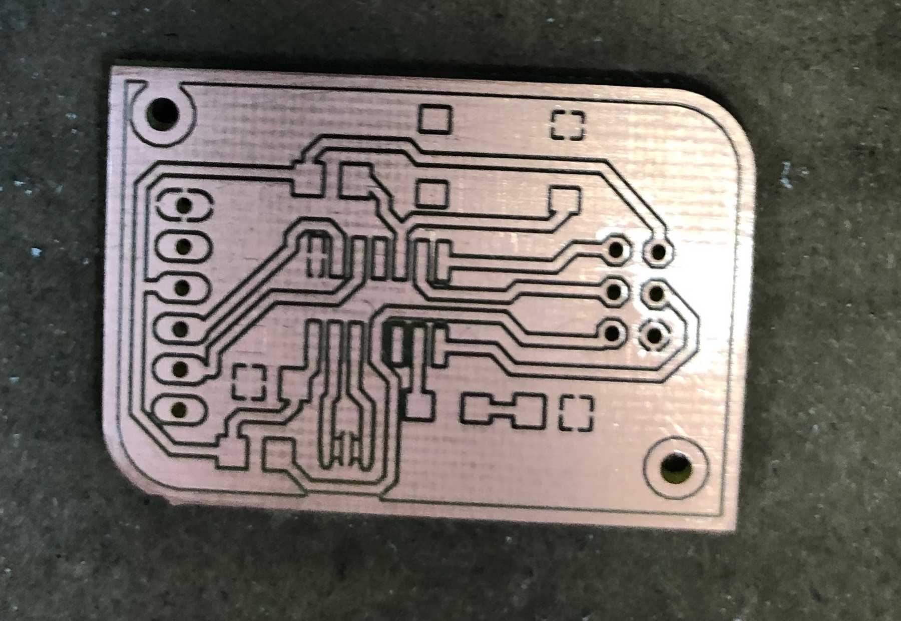

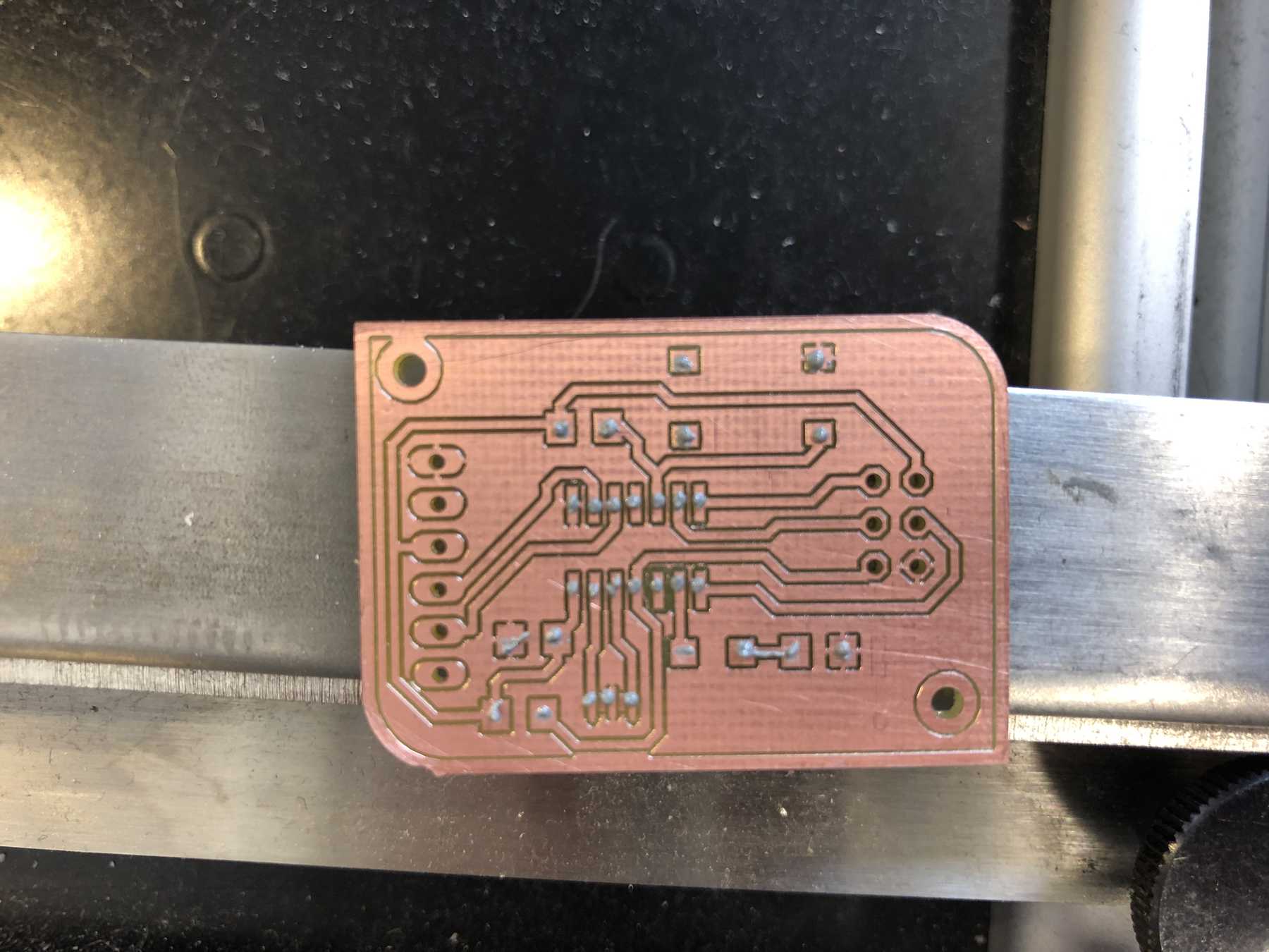
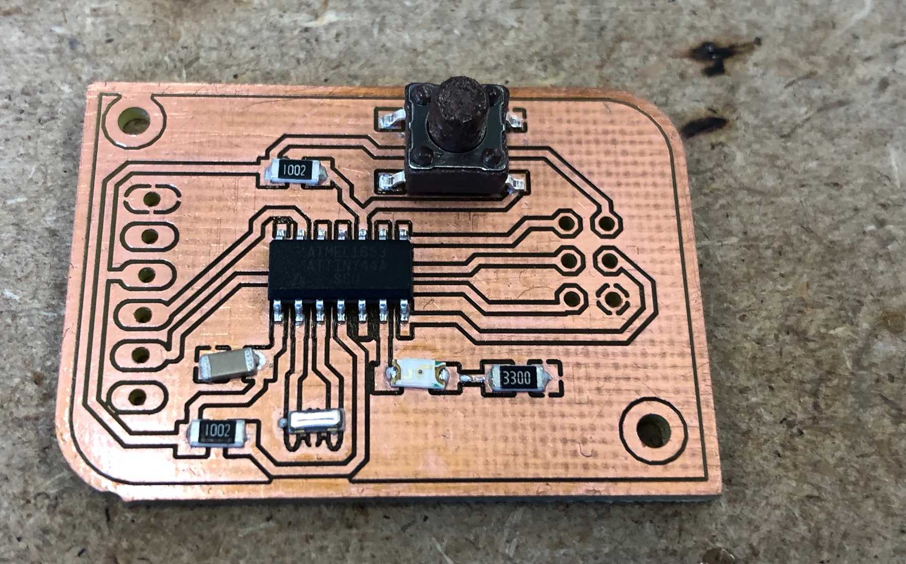
The following picture includes the final board.
Programming
Many nerves were lost in this phase, as was the number of days. Actually, if everything works, this part will be done in 10 minutes. Plug it in, put the bootloader on it, install the program code and it runs. That was an illusion!
I started downloading the following files from the Fab Academy page. In the terminal, I changed to the correct folder with the cd command. I renamed the file hello.ftdi.44.echo.c.make with the command mv hello.ftdi.44.echo.c.make Makefile in the terminal.
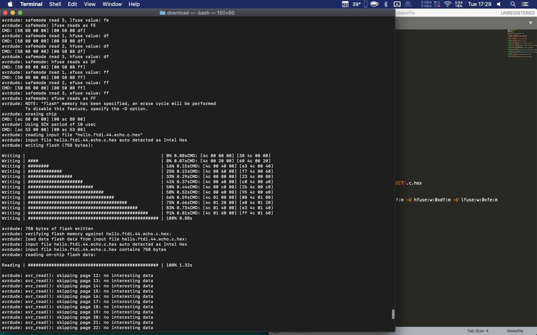
The Make command creates the necessary .hex file. This worked:
I have connected my usbtiny via ISP to my hello-world board. Unfortunately this did not work, there was always only the following error message.
Finally I tried to address the device of the usbtiny directly. That doesn’t work either - because there is no /dev/ device for it. So what now? A lot of google research didn’t help me either, so I ended up with try & error.
I tried many things and one thing that came to mind was to load the bootloader directly onto the ATtiny44 via the Arduino IDE. Under the Board Manager (Preferences) I added the library with the following url:
https://raw.githubusercontent.com/damellis/attiny/ide-1.6.x-boards-manager/package_damellis_attiny_index.json
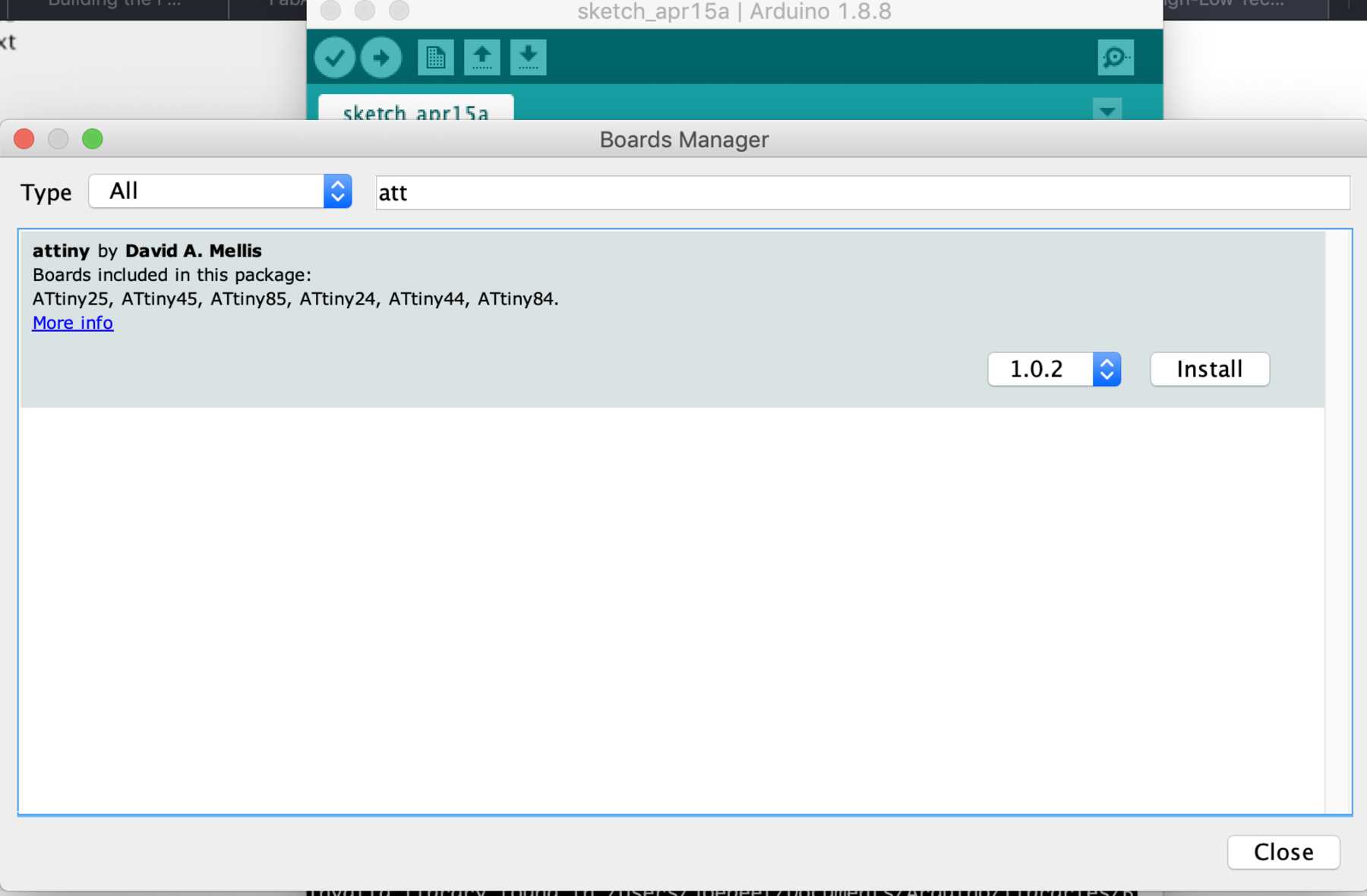
This enables a package with support for the ATtiny24/44/84, which you can select under Tools - Boards. With Tools - Processor I selected the ATtiny44. Said, done. Burn Bootloader under Tools - Burn Bootloader.
It worked. And now? Why does he address my FabTinyISP directly here? What is the difference? Via the verbose-mode I looked at the code and copied it directly into my terminal. It didn’t work either. Only the Arduino version worked. So I checked which version of AVRDUDE was installed before: 5.0.1. A look over google told me: 6.3 is current. Something went wrong here.
First at the terminal:
ruby -e "$(curl -fsSL https://raw.githubusercontent.com/Homebrew/install/master/install)" < /dev/null 2> /dev/null
Then …
brew install avrdude
Just tried the previous command make and see there: everything worked.
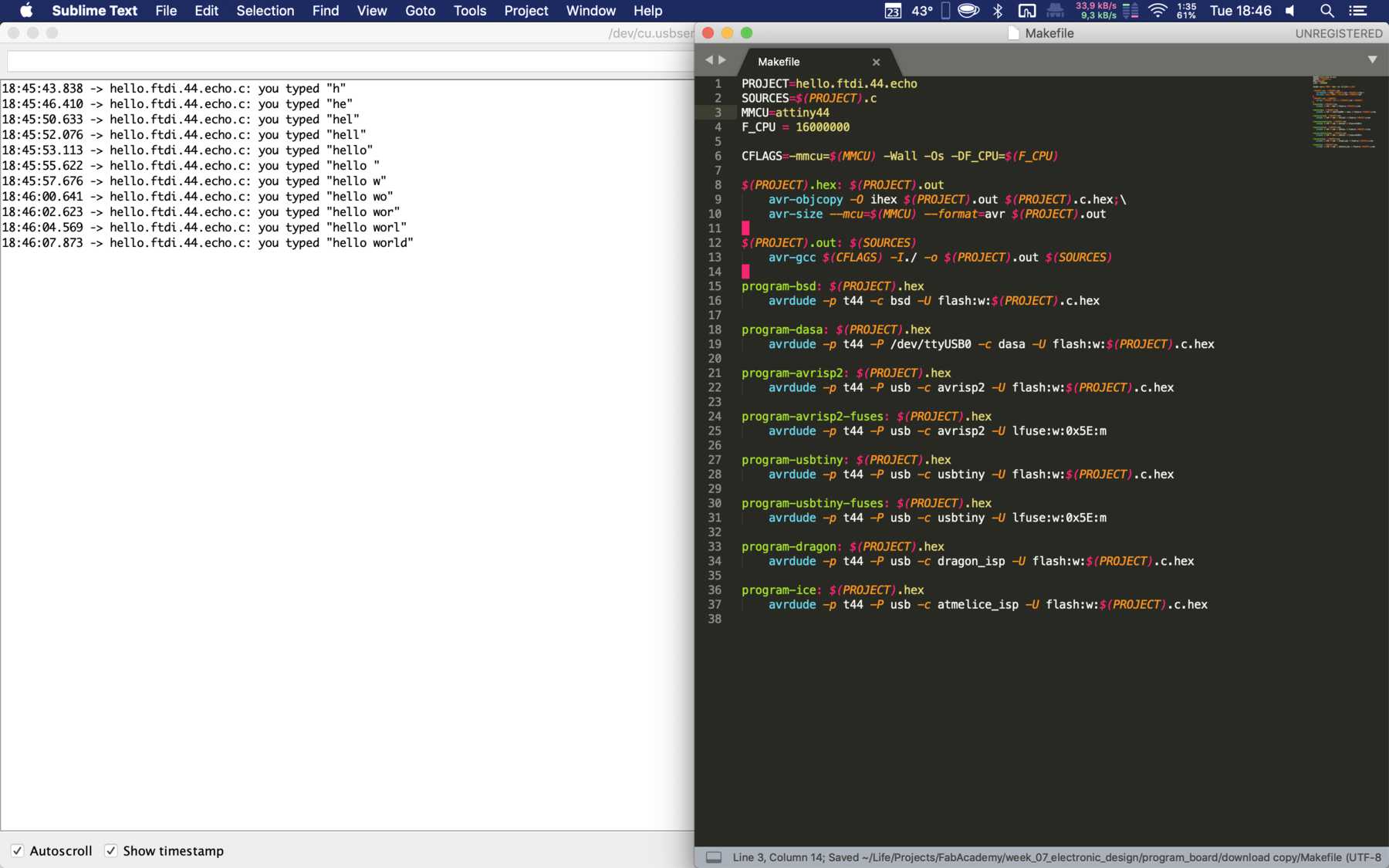
I lost a lot of time by installing the wrong version of AVRDUDE on my mac. Next I realized that I had a 16MHz crystal on my board and not a 20MHz. I changed this in the Makefile file as follows. With the command make program-usbtiny and program-usbtiny-fuses I could upload the files to ATtiny44.
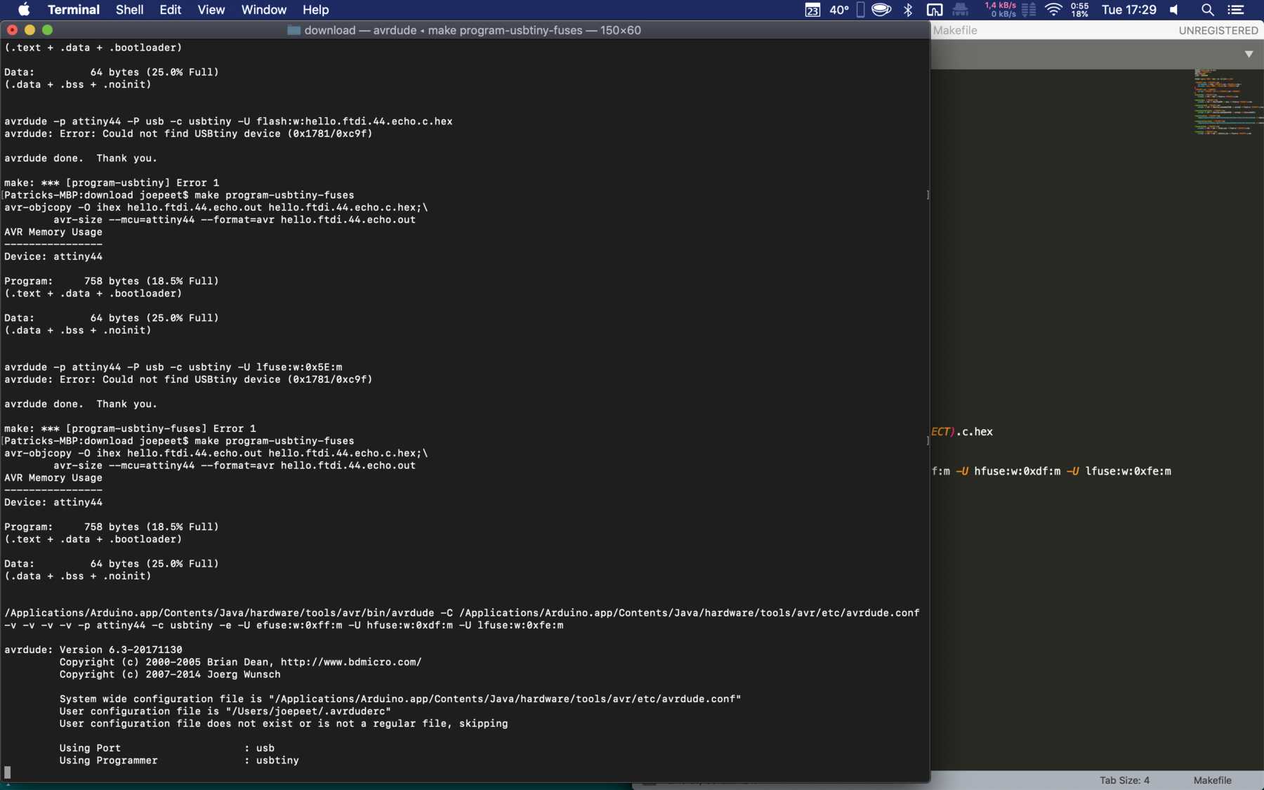
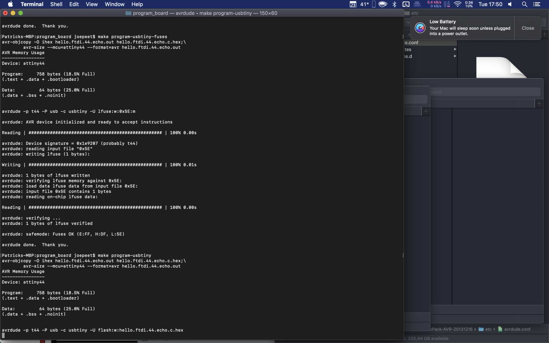
You could also upload the files directly with the avrdude command: avrdude -p t44 -P usb -c usbtiny -U flash:w:hello.ftdi.44.echo.c.hex and avrdude -p t44 -P usb -c usbtiny -U lfuse:w:0x5E:m.
The following video shows Neil’s test script with “hello world” - unfortunately the video doesn’t show my joy that it finally worked:
Here you can download the EAGLE files for my hello world board:
EAGLE files