
13/3/2019
Compare the performance and development workflows for other architectures
Read a microcontroller data sheet, program your board to do something with as many different programming languages and programming environments as possible


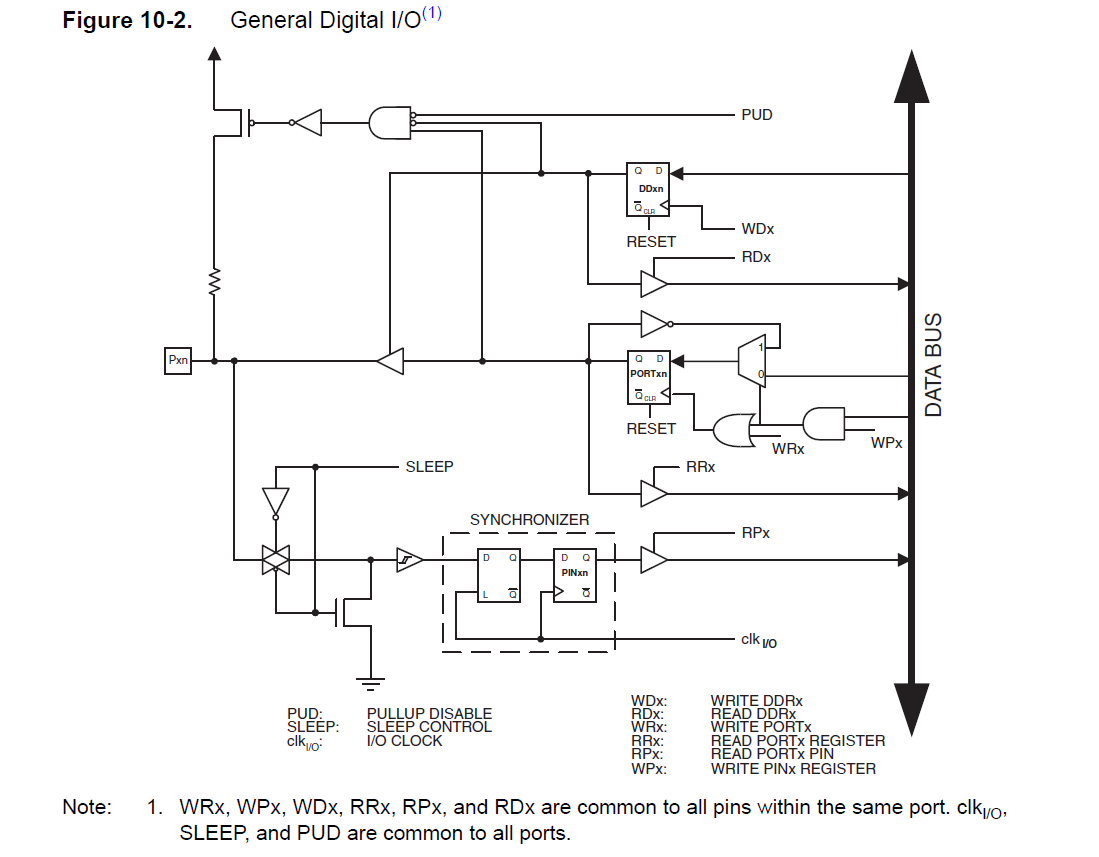
Each port pin consists of three register bits: DDxn, PORTxn, and PINxn. As shown in “Register Description” on page 66, the DDxn bits are accessed at the DDRx I/O address, the PORTxn bits at the PORTx I/O address, and the PINxn bits at the PINx I/O address
The DDxn bit in the DDRx Register selects the direction of this pin. If DDxn is written logic one, Pxn is configured as an output pin. If DDxn is written logic zero, Pxn is configured as an input pin
If PORTxn is written logic one when the pin is configured as an input pin, the pull-up resistor is activated. To switch the pull-up resistor off, PORTxn has to be written logic zero or the pin has to be configured as an output pin. The port pins are tri-stated when reset condition becomes active, even if no clocks are running
If PORTxn is written logic one when the pin is configured as an output pin, the port pin is driven high (one). If PORTxn is written logic zero when the pin is configured as an output pin, the port pin is driven low (zero)
When switching between tri-state ({DDxn, PORTxn} = 0b00) and output high ({DDxn, PORTxn} = 0b11), an intermediate state with either pull-up enabled {DDxn, PORTxn} = 0b01) or output low ({DDxn, PORTxn} = 0b10) must occur. Normally, the pull-up enabled state is fully accept- able, as a high-impedant environment will not notice the difference between a strong high driver and a pull-up. If this is not the case, the PUD bit in the MCUCR Register can be set to disable all pull-ups in all ports
Switching between input with pull-up and output low generates the same problem. The user must use either the tri-state ({DDxn, PORTxn} = 0b00) or the output high state ({DDxn, PORTxn} = 0b10) as an intermediate step
Table 10-1 summarizes the control signals for the pin value

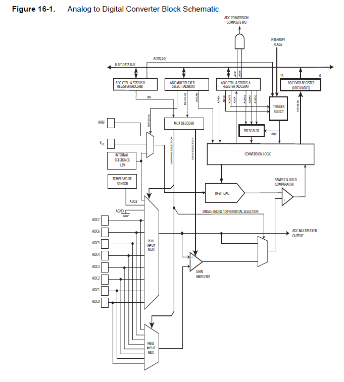
Above were the main information or summary of the ATTINY 44 Datasheet and the most essential bits that we need to know...
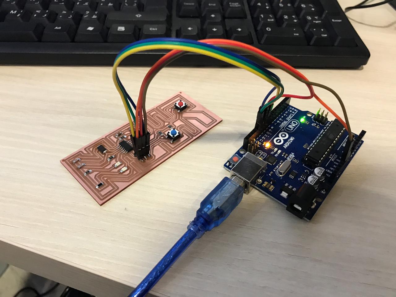
First thing is to identify the components of my hello board and which are the following:
Then we should follow the same steps done during week7as per the below for doing TEST PROGRAM 1:
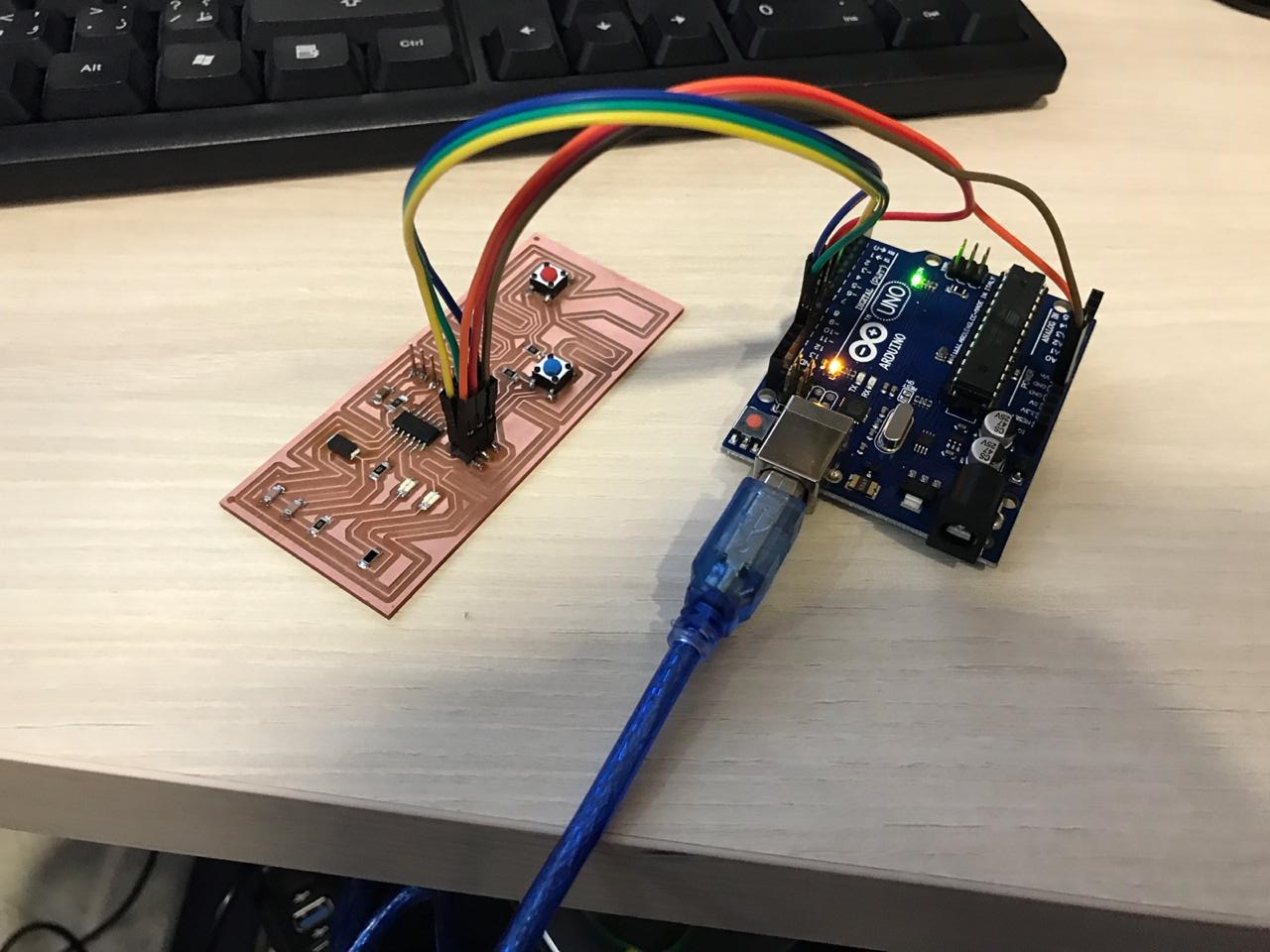
The programming will take place using ARDUINO UNO; So the first thing that needs to happen is to let the Arduino work as ISP so that we can use it to program the board for the very first time
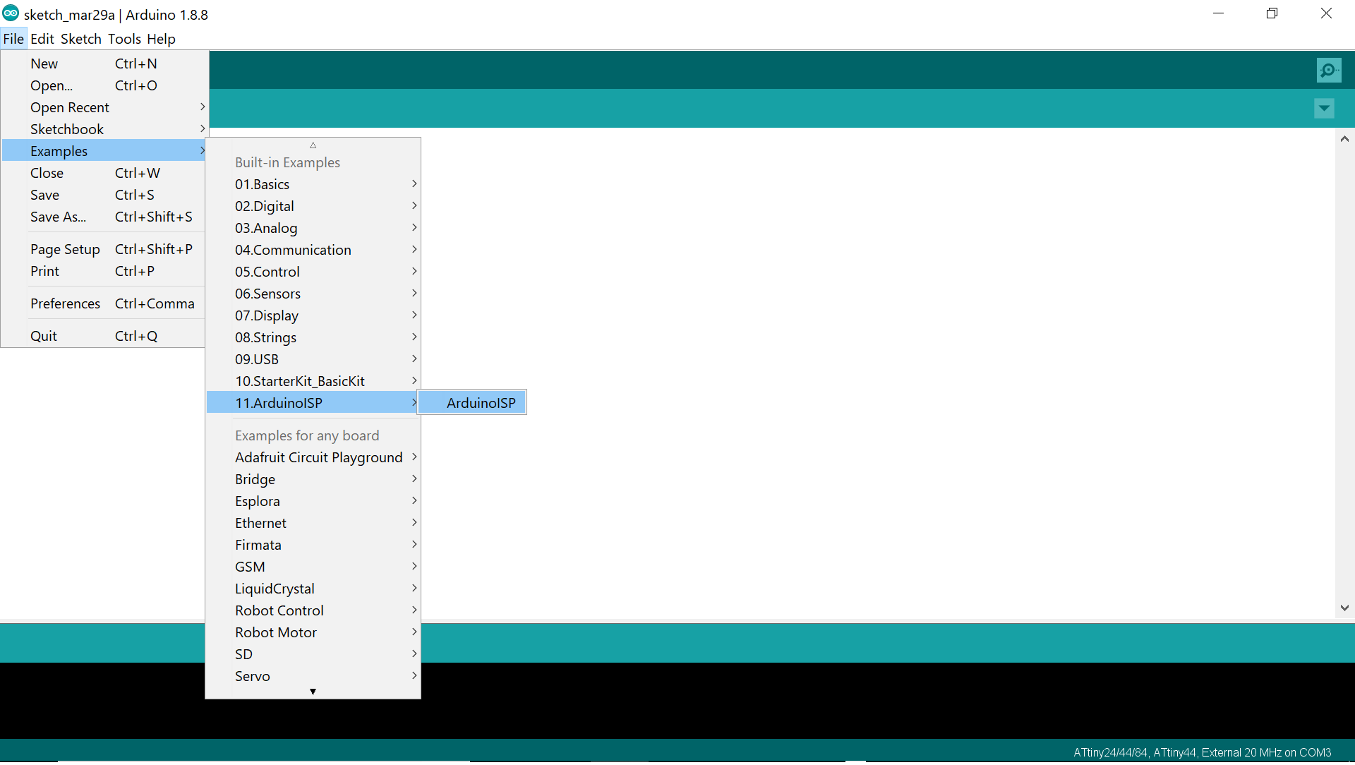
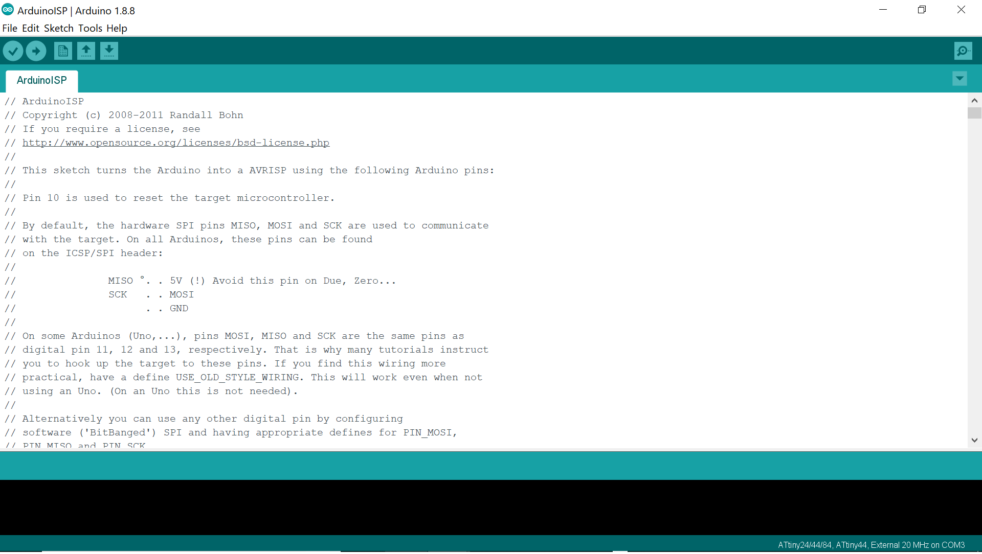
For doing so, we open the Arduino IDE and we connect the Arduino UNO board to the laptop and upload the ArduinoISP sketch from examples to the ARDUINO UNO board all while making sure to select the ARDUINO UNO in boards and the right port as per the below:

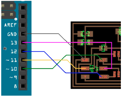
Then disconnect, and connect the hello board to the Arduino board via the ISP on the board following the below schemata and reconnect it to the laptop
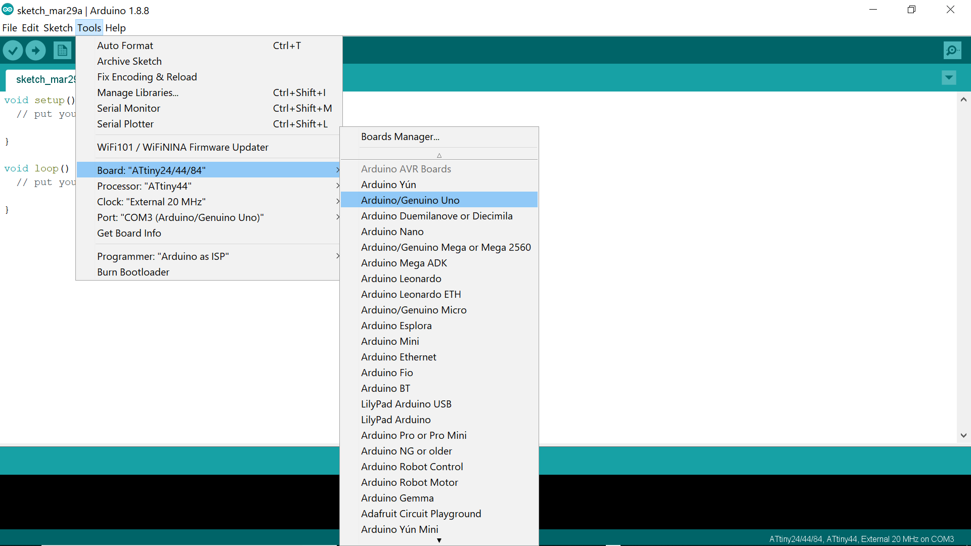
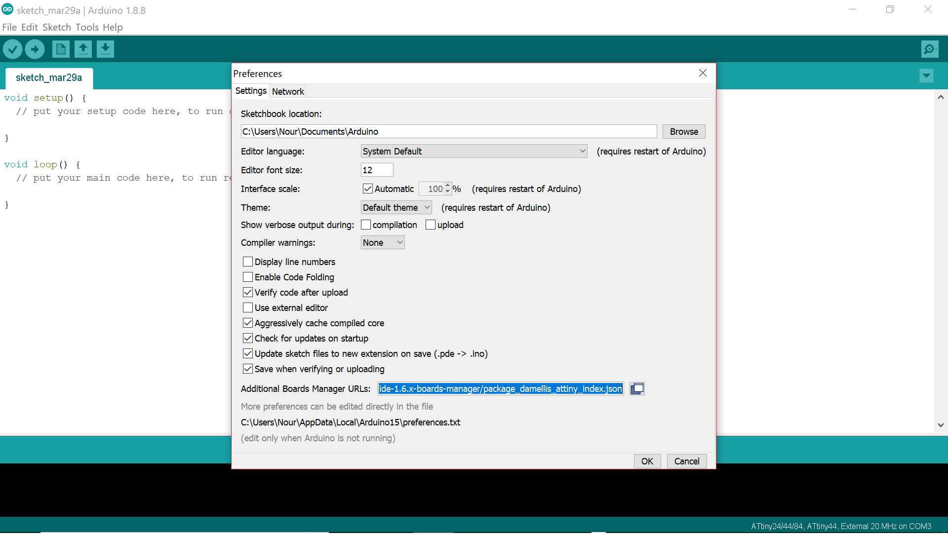
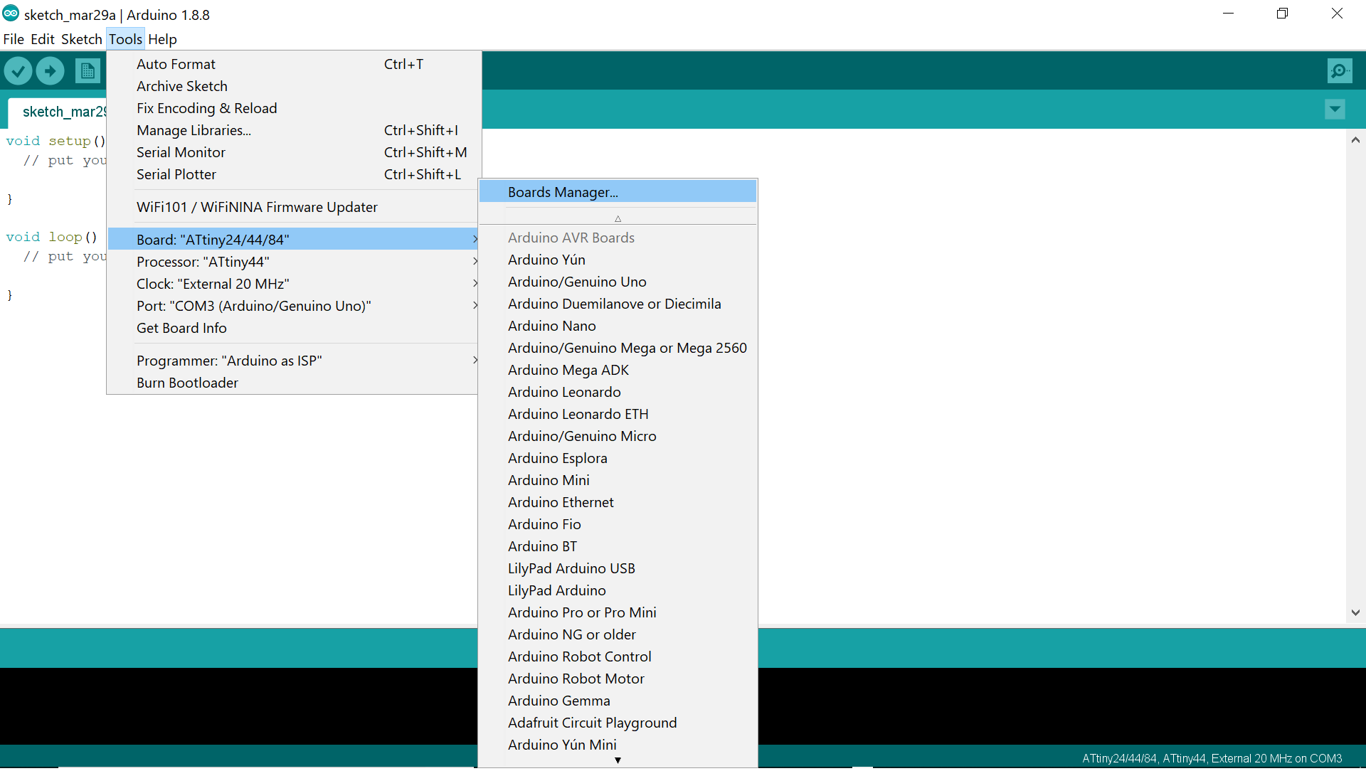
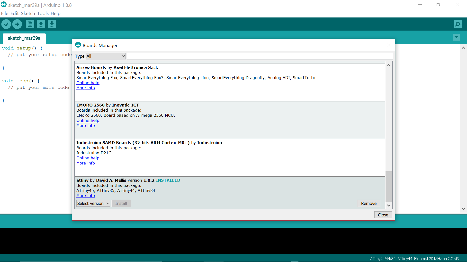
The microcontroller on the Hello Board is the ATTINY 44 so we need to make it clear for the ARDUINO that it is dealing with this MCU. And for doing so, we need to install the ATTINY 44 by going to FILE>PREFERENCES and inserting the following link: "https://raw.githubusercontent.com/damellis/attiny/ide-1.6.x-boards-manager/package_damellis_attiny_index.json" in the Additional Boards Manager URLs
Then go to TOOLS> Boards Manager and install the attiny44 then choose processor as Attiny44 and select clock
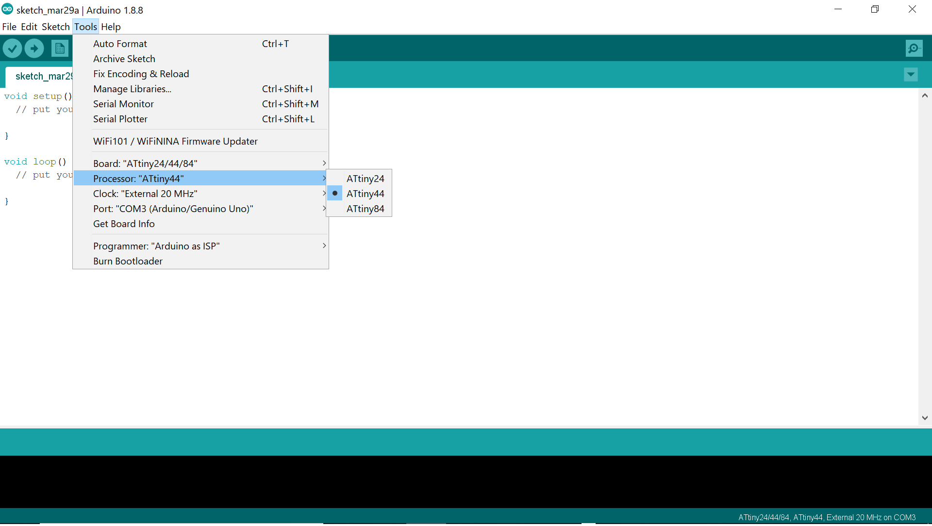
Then select programmer as ArduinoISP, burn Bootloader, and finally upload my sketch
In order to write down my sketch, I need to know the below connections that explain how the ATTINY44 can be connected to an ARDUINO
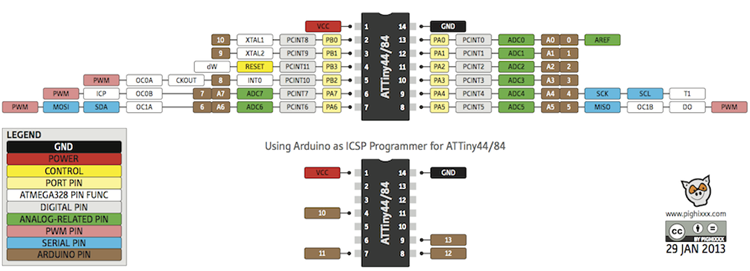
Following the above, we can note the following:
And here is the sketch that I have used in which I wanted the red button to light up the red LED when pressed for 1 second and the blue button to light up the blue LED when pressed for 1 second
  // constants won't change. Used here to set a pin number:
                        const int button1Pin = 3;//the number of the pushbutton pin
                        const int button2Pin = 2;//the number of the pushbutton pin
                        const int ledPingreen = 7;// the number of the greenLED pin
                        const int ledPinred = 8;// the number of the redLED pin

                        // Variables will change:
                        int ledState = LOW; // ledState used to set the LED

                        int button1State = 0;
                        int button2State = 0;
                        int sensorValue = 0; // variable to store the value coming from the sensor


                        void setup()
                        {
                        // put your setup code here, to run once:
                        // set the digital pin as output:
                        pinMode(ledPingreen, OUTPUT);
                        pinMode(ledPinred, OUTPUT);

                        // set the digital pin as input:
                        pinMode(button1Pin, INPUT);
                        pinMode(button2Pin, INPUT);

                        }

                        void loop()
                        {
                        // read the state of the pushbutton value:
                        button1State = digitalRead(button1Pin);
                        button2State = digitalRead(button2Pin);

                        // check if the pushbutton is pressed. If it is, the buttonState is HIGH:
                        if (button1State == LOW)
                        {
                        // put your main code here, to run repeatedly:
                        digitalWrite(ledPingreen, HIGH); // turn the LED on (HIGH is the voltage level)
                        digitalWrite(ledPinred, LOW); // turn the LED on (HIGH is the voltage level)
                        delay(1000);
                        }
                        else
                        {
                        digitalWrite(ledPingreen, LOW); // turn the LED off by making the voltage LOW
                        digitalWrite(ledPinred, LOW); // turn the LED off by making the voltage LOW
                        }
                        // wait for a second
                        // check if the pushbutton is pressed. If it is, the buttonState is HIGH:

                        if (button2State == LOW)
                        {
                        // put your main code here, to run repeatedly:
                        digitalWrite(ledPingreen, LOW); // turn the LED on (HIGH is the voltage level)
                        digitalWrite(ledPinred, HIGH); // turn the LED on (HIGH is the voltage level)
                        delay(1000);
                        }
                        else
                        {
                        digitalWrite(ledPingreen, LOW); // turn the LED off by making the voltage LOW
                        digitalWrite(ledPinred, LOW); // turn the LED off by making the voltage LOW
                        }

                        }
And you may finally check out the test working in the video below!!
In order to understand the ARDUINO coding language, I have watched several tutorials that you may refer too and read some books too:
I am now able to explain the commands that we are using and the syntax:
Time to test different programs:
In this test, I want the LED to blink while keep pushing the button
                              // constants won't change. Used here to set a pin number:
                        const int button1Pin = 3;//the number of the pushbutton pin
                        const int button2Pin = 2;//the number of the pushbutton pin
                        const int ledPingreen = 7;// the number of the greenLED pin
                        const int ledPinred = 8;// the number of the redLED pin

                        // Variables will change:
                        int ledState = LOW; // ledState used to set the LED

                        int button1State = 0;
                        int button2State = 0;
                        int sensorValue = 0; // variable to store the value coming from the sensor


                        void setup()
                        {
                        // put your setup code here, to run once:
                        // set the digital pin as output:
                        pinMode(ledPingreen, OUTPUT);
                        pinMode(ledPinred, OUTPUT);

                        // set the digital pin as input:
                        pinMode(button1Pin, INPUT);
                        pinMode(button2Pin, INPUT);

                        }

                        void loop()
                        {
                        // read the state of the pushbutton value:
                        button1State = digitalRead(button1Pin);
                        button2State = digitalRead(button2Pin);

                        // check if the pushbutton is pressed. If it is, the buttonState is HIGH:
                        if (button1State == LOW)
                        {
                        // put your main code here, to run repeatedly:
                        digitalWrite(ledPingreen, HIGH); // turn the LED on (HIGH is the voltage level)
                        digitalWrite(ledPinred, LOW); // turn the LED on (HIGH is the voltage level)
                        delay(1000);
                        digitalWrite(ledPingreen, LOW); // turn the LED on (HIGH is the voltage level)
                        digitalWrite(ledPinred, LOW); // turn the LED on (HIGH is the voltage level)
                        delay(1000);
                        }
                        else
                        {
                        digitalWrite(ledPingreen, LOW); // turn the LED off by making the voltage LOW
                        digitalWrite(ledPinred, LOW); // turn the LED off by making the voltage LOW
                        }
                        // wait for a second
                        // check if the pushbutton is pressed. If it is, the buttonState is HIGH:

                        if (button2State == LOW)
                        {
                        // put your main code here, to run repeatedly:
                        digitalWrite(ledPingreen, LOW); // turn the LED on (HIGH is the voltage level)
                        digitalWrite(ledPinred, HIGH); // turn the LED on (HIGH is the voltage level)
                        delay(1000);
                        digitalWrite(ledPingreen, LOW); // turn the LED on (HIGH is the voltage level)
                        digitalWrite(ledPinred, LOW); // turn the LED on (HIGH is the voltage level)
                        delay(1000);
                        }
                        else
                        {
                        digitalWrite(ledPingreen, LOW); // turn the LED off by making the voltage LOW
                        digitalWrite(ledPinred, LOW); // turn the LED off by making the voltage LOW
                        }

                        }
And you may finally check out the test working in the video below!!