27/2/2019
Use the test equipment in your lab to observe the operation of a microcontroller circuit board
Redraw the echo hello-world board, add (at least) a button and LED (with current-limiting resistor). Check the design rules, make it, and test it. Extra credit: simulate its operation
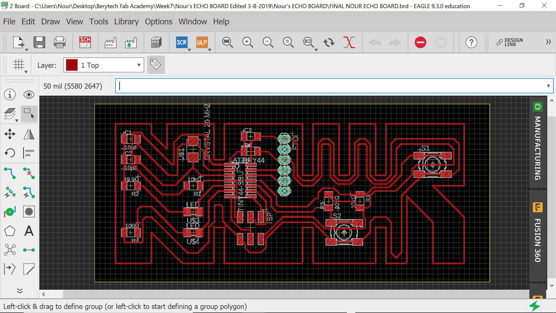
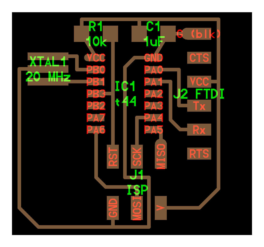
Redraw the echo hello-world board like the below schematic and which needs to look something like the other real photo
So the main components used in the echo hello-board are the below:
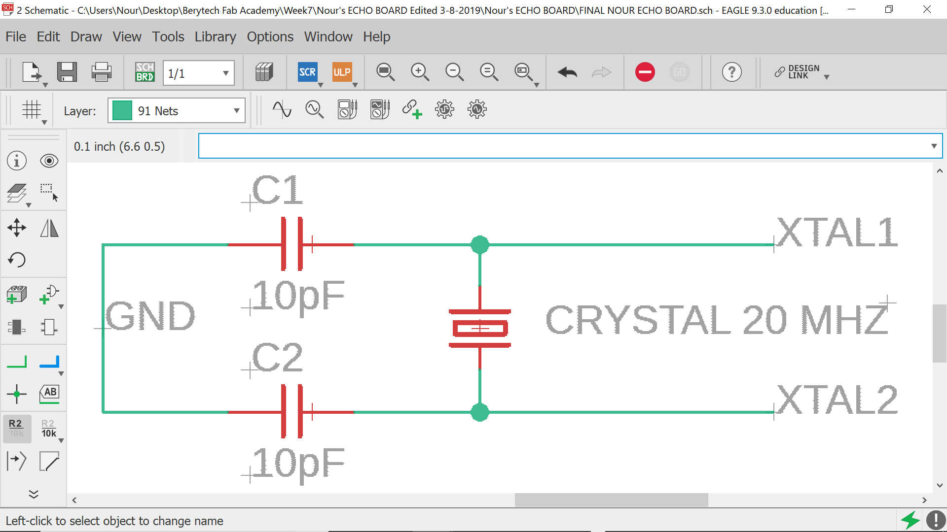
In our case, we will not use a resonator like the image above; We will use a crystal of MHz and which needs two capacitors of 8pF. However, the available capacitors we have at the lab are of 10pF. The latter need to be added to the above list as per the following:
In order to understand the role of each component used in the echo hello-board you need to know that:
In general, most of the components have GND (ground), VCC (voltage).
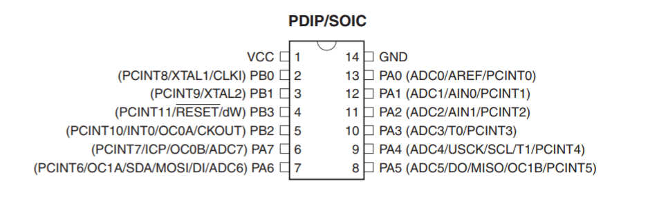
According to its datasheet , the Attiny 44 has the following pins:
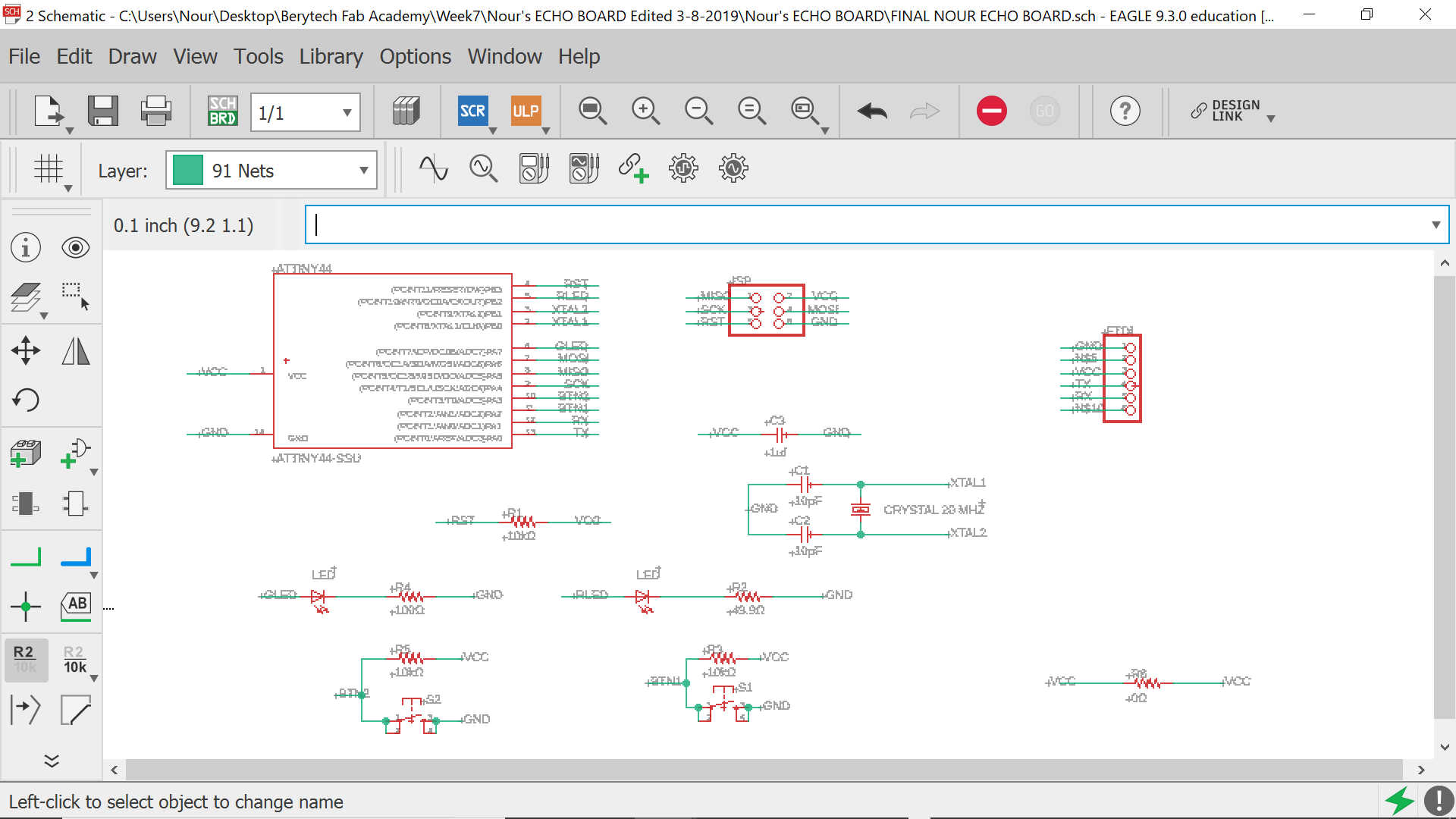
We can start redrawing the echo hello-board on Eagle before adding the needed components (button and LED)
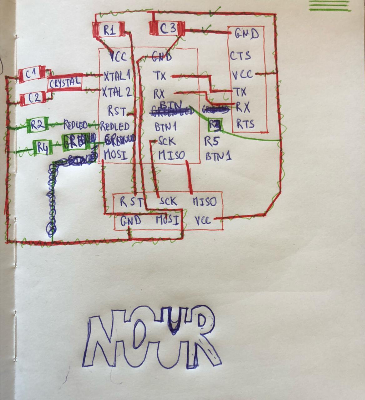
Before starting to draw on Eagle, I have tried to sketch the connections on my sketchbook so I can understand better the wiring and had the idea of having the board in the shape of my name. But I will start first by drawing the basic shape of the board and then modify it...
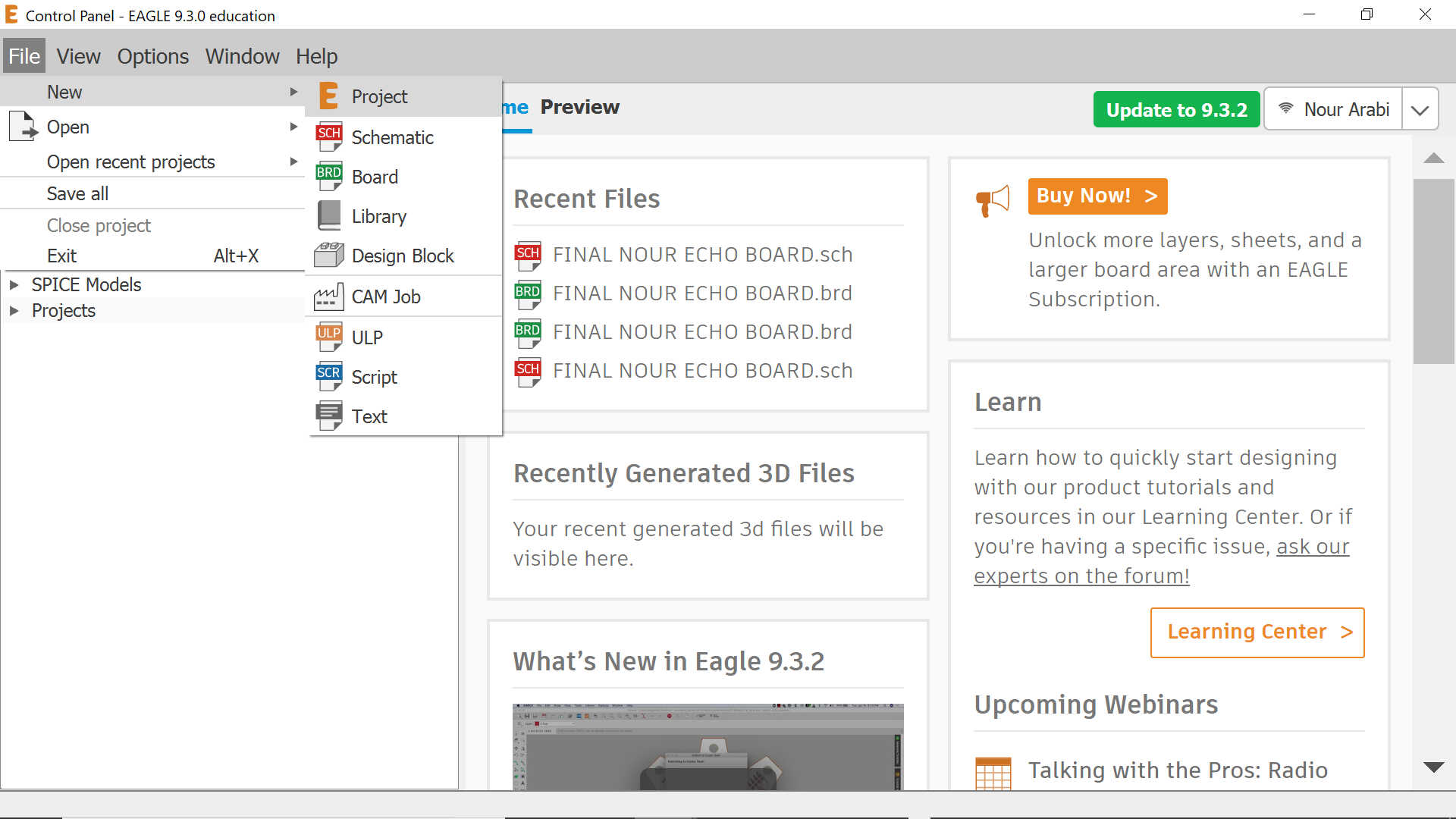
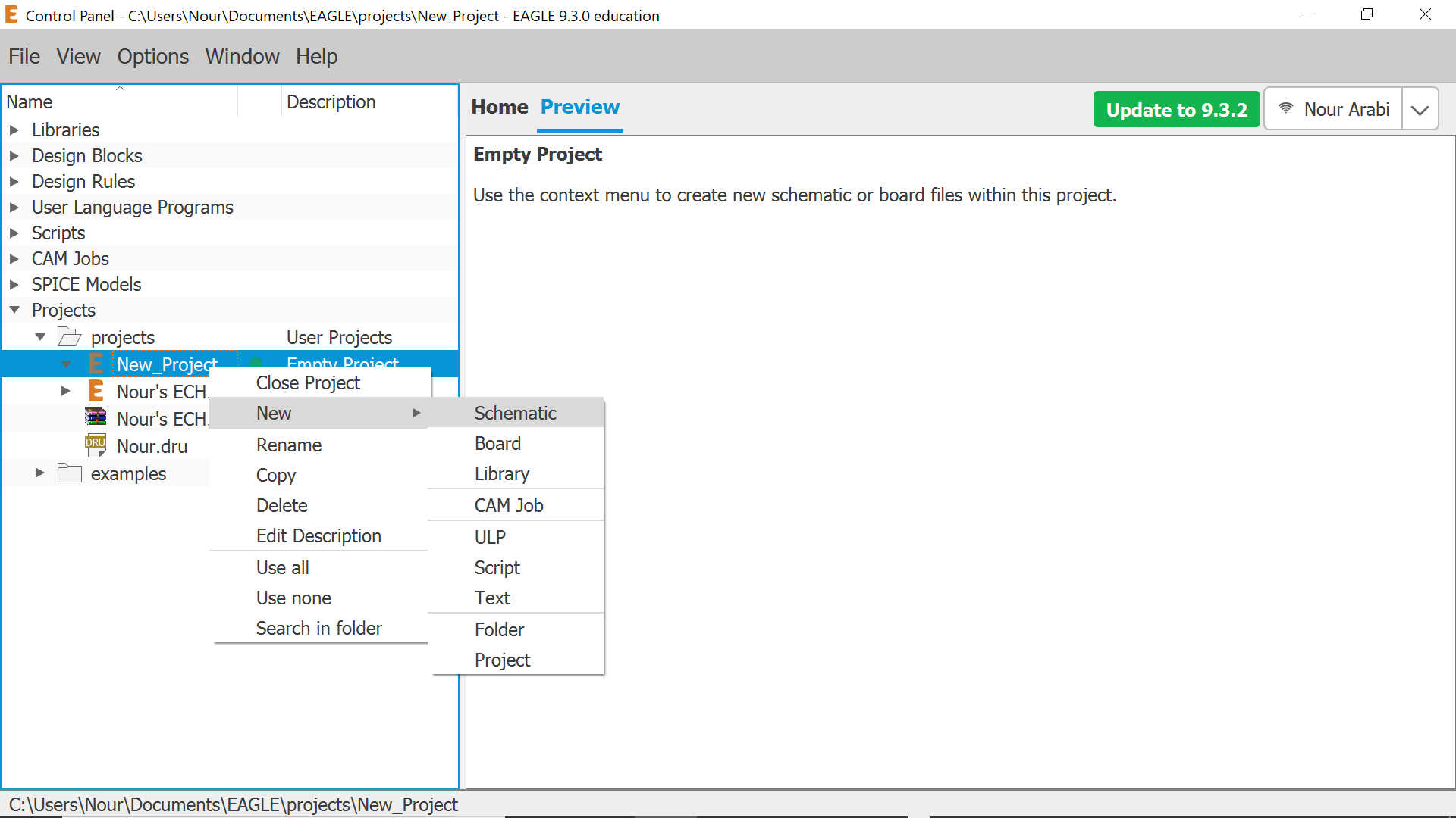
The first thing you need to do when opening Eagle is to open a new project and a new schematic as per the below photos. So the schematic is the main sketch of your components and how they are going to be logically connected before actually drawing the final routes or wires of the board; All your files will be saved in one folder, which is the folder of your project
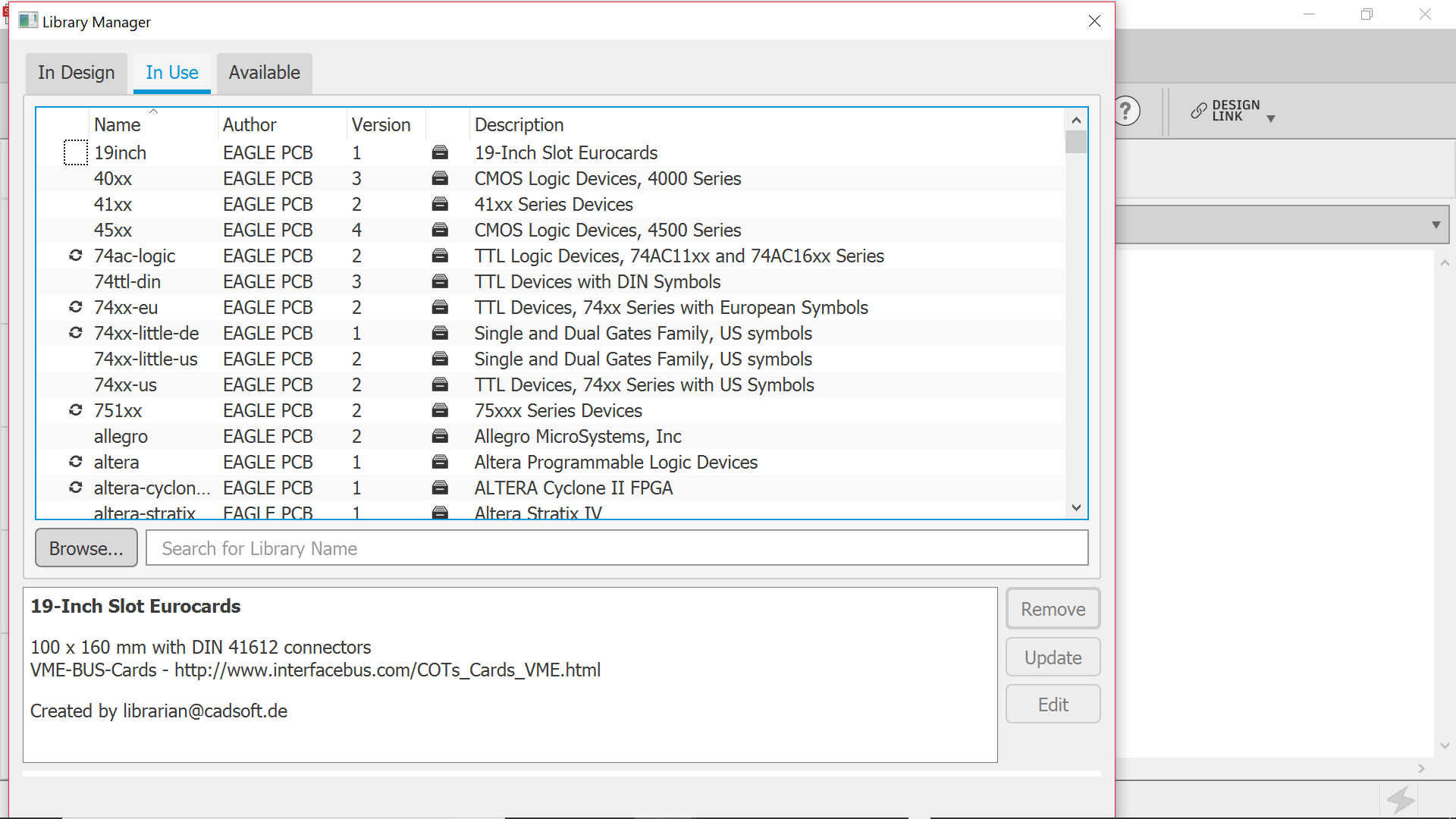
You will then need to add the fab library which you may download from here
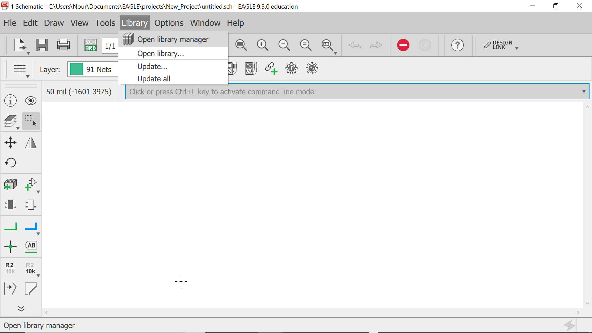
In order to add it, click on Library then Open Library Manager. Go to In Use and browse for the fab library and open it
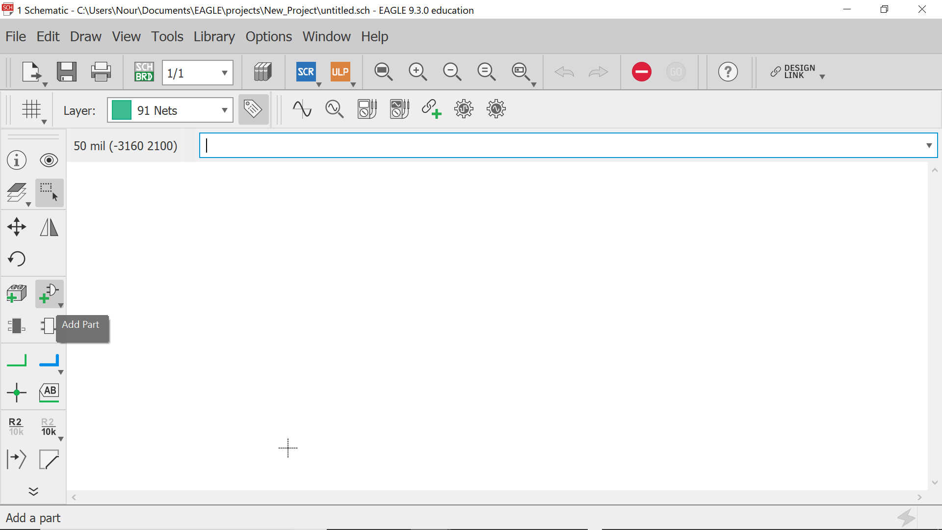
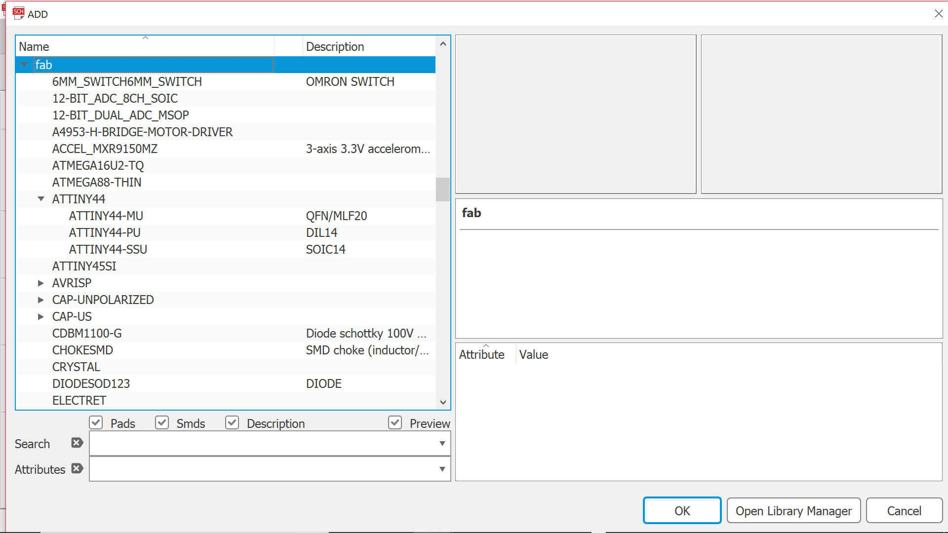
Then you may start placing your components by clicking on the Add Part icon and look for them under the fab library section -as per the below example
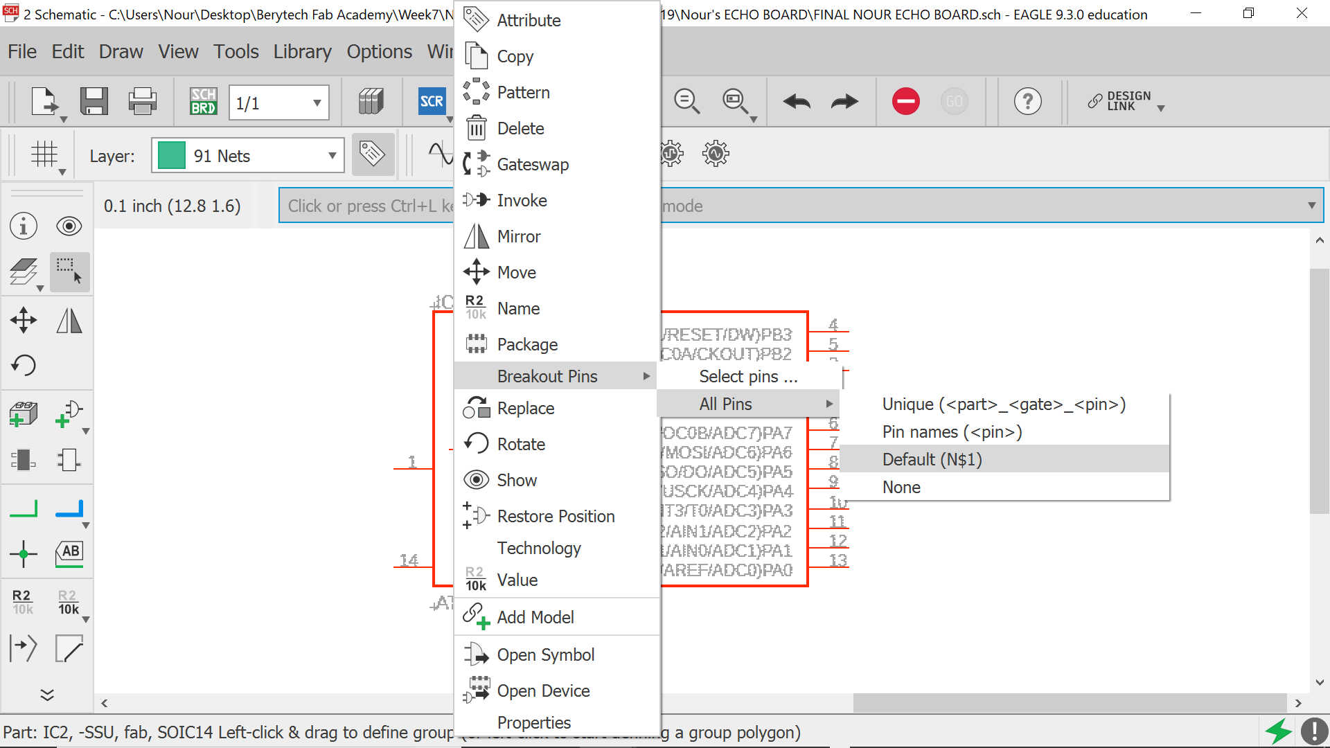
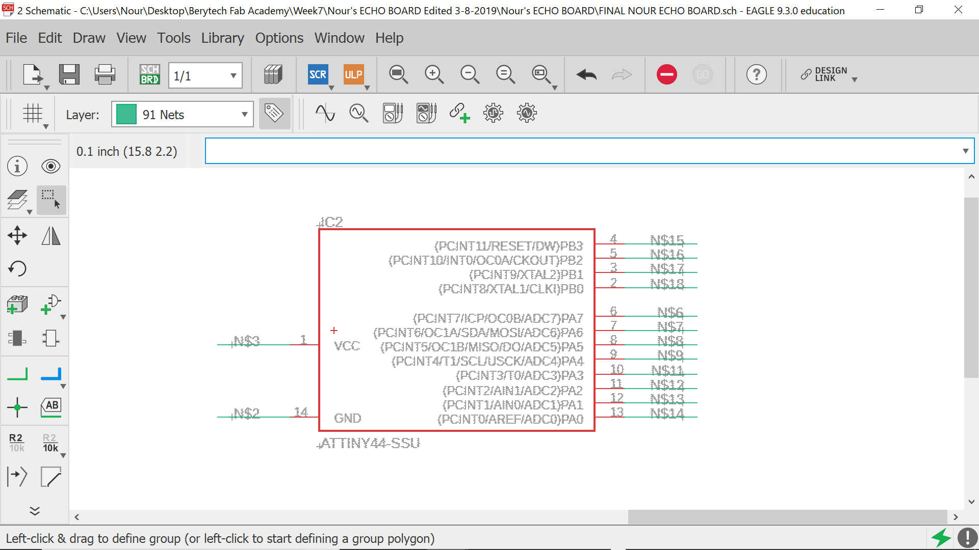
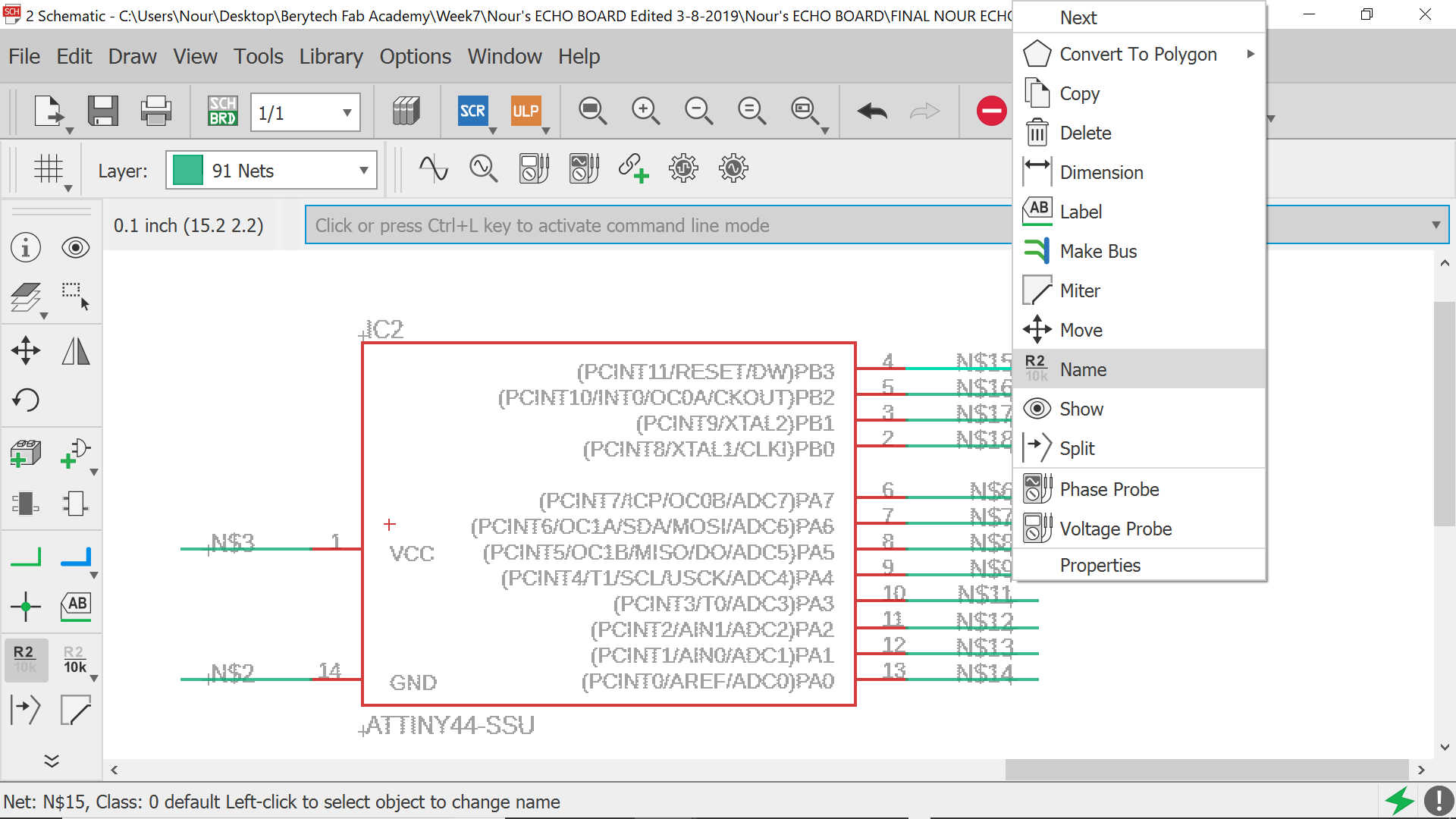
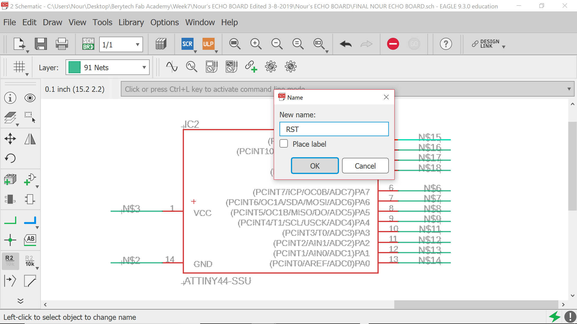
For each component, we need to add its breakout default pins and name them and accept that they get connected
The same process needs to be done for all other components, all while adding the corresponding values
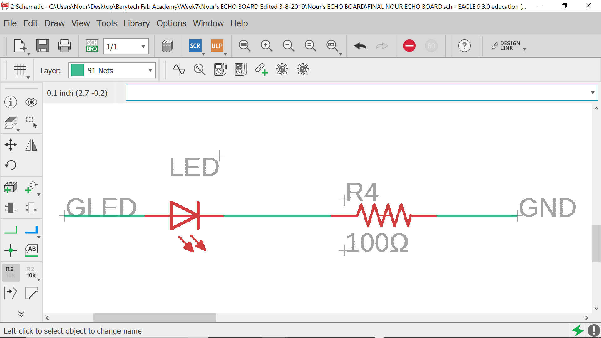
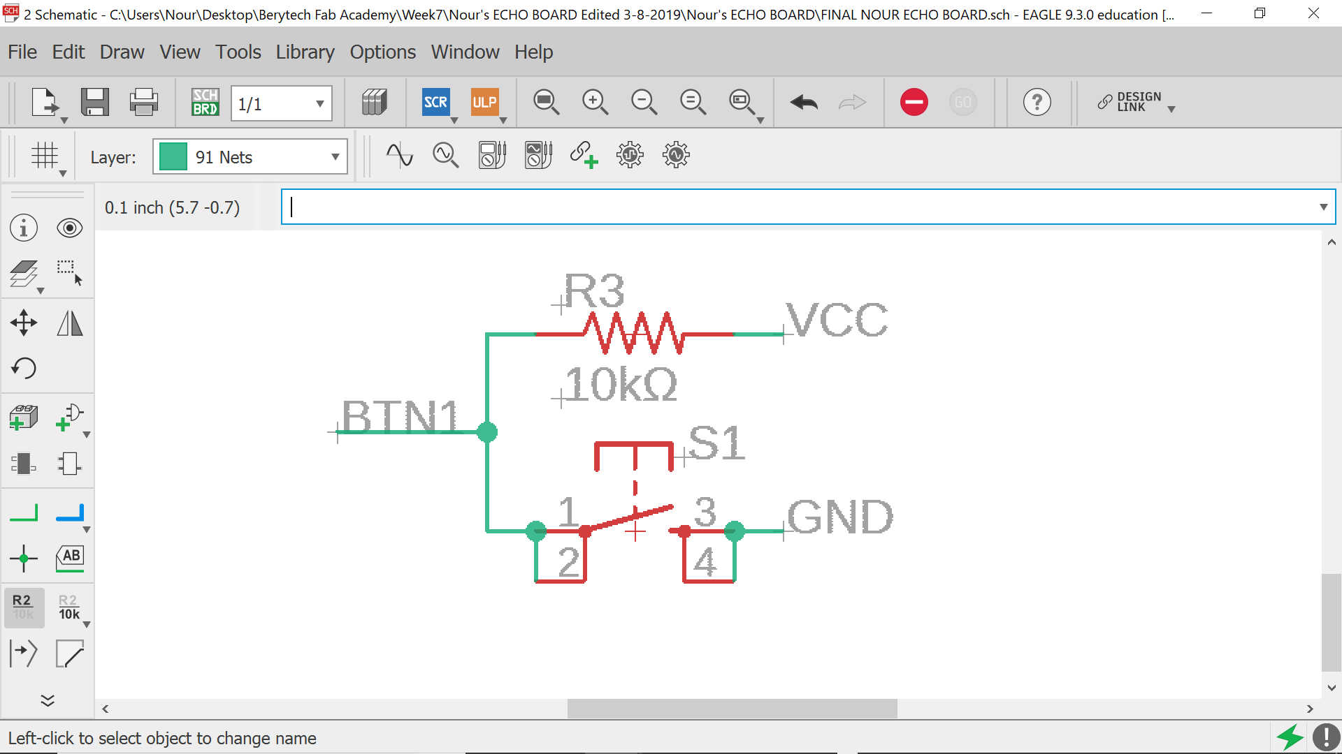
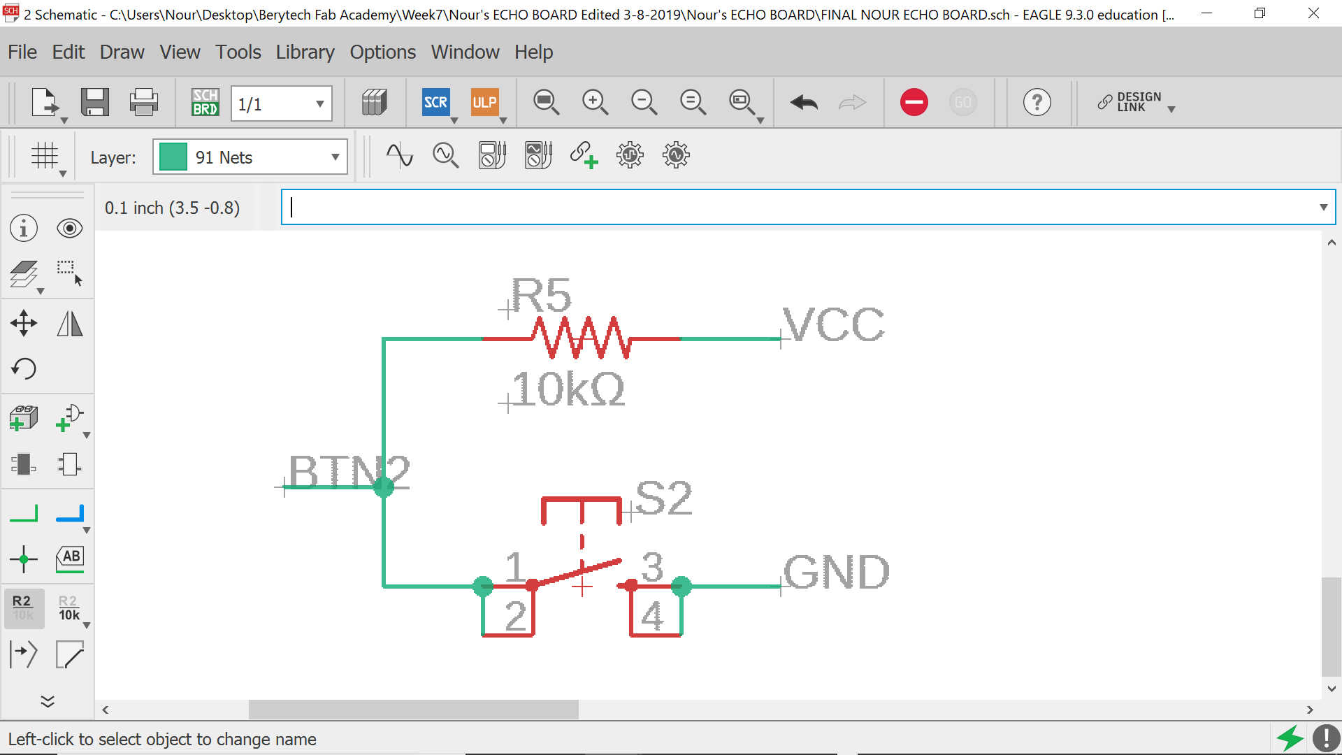
It is crucial here to point out that I have decided to add 2 buttons and 2 leds: one red and one green
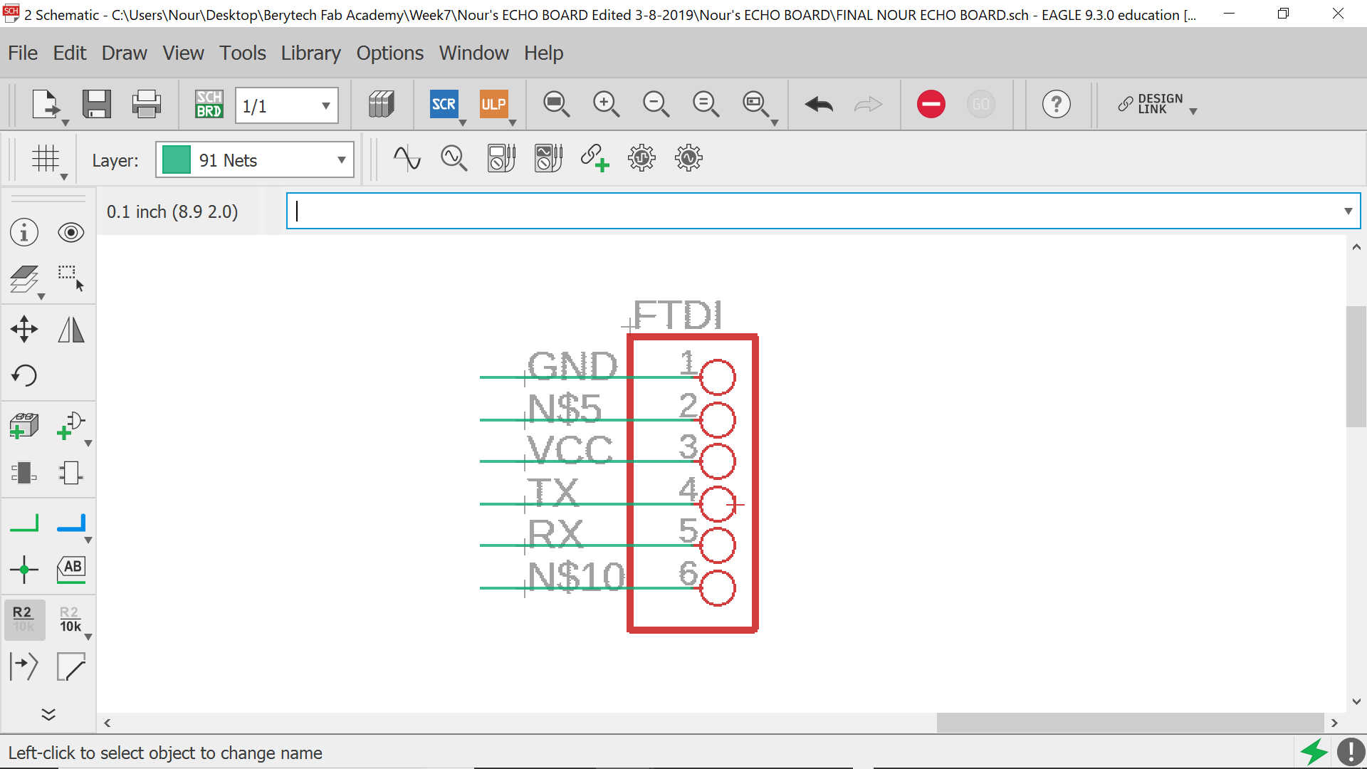
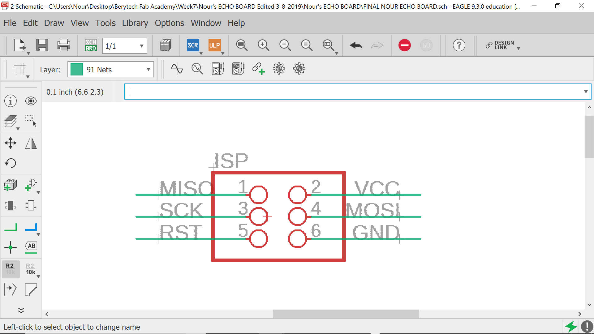
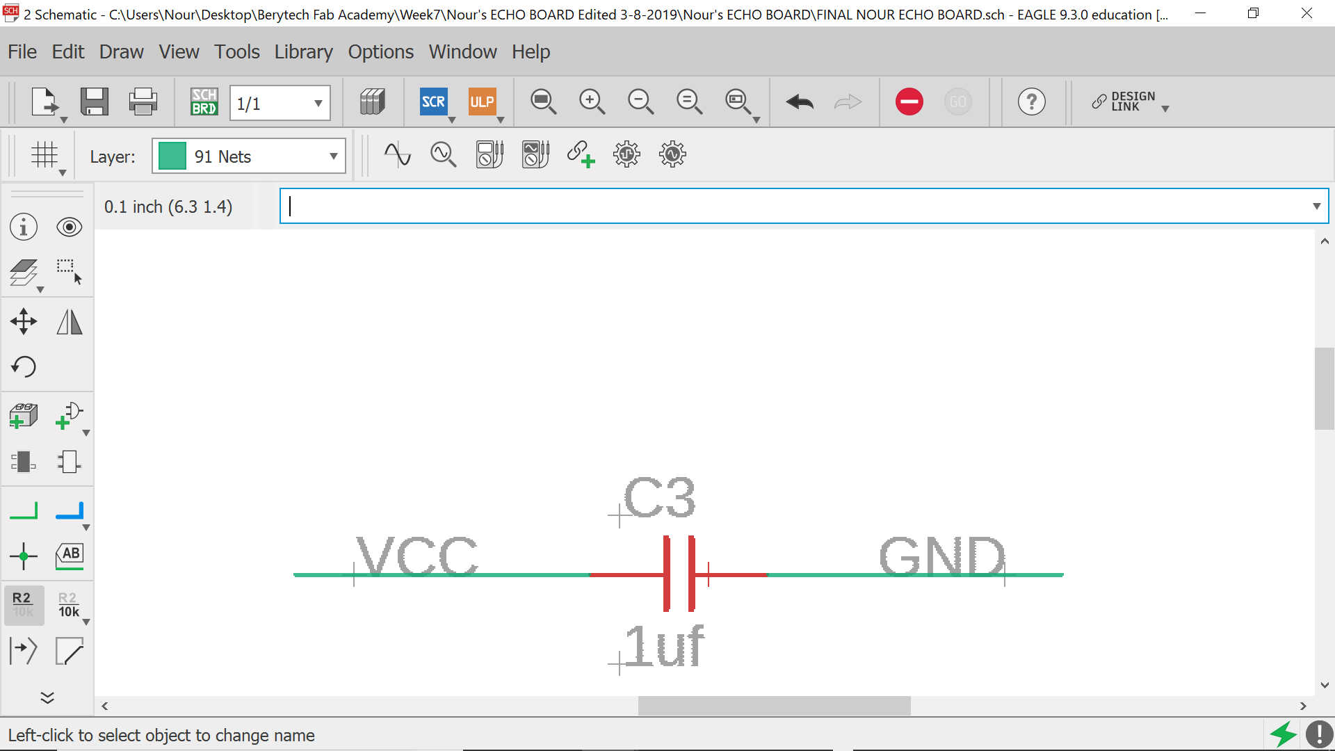
The default connections for the FTDI, ISP and capacitor are as per the below:
Below you may find the connections of the Crystal with the 2 capacitors as per its datasheet
And according to the red LED datasheet, and as per the below equation, we can calculate the resistance needed and which is 86.6Ω. The closest number available at the lab is 100Ω.
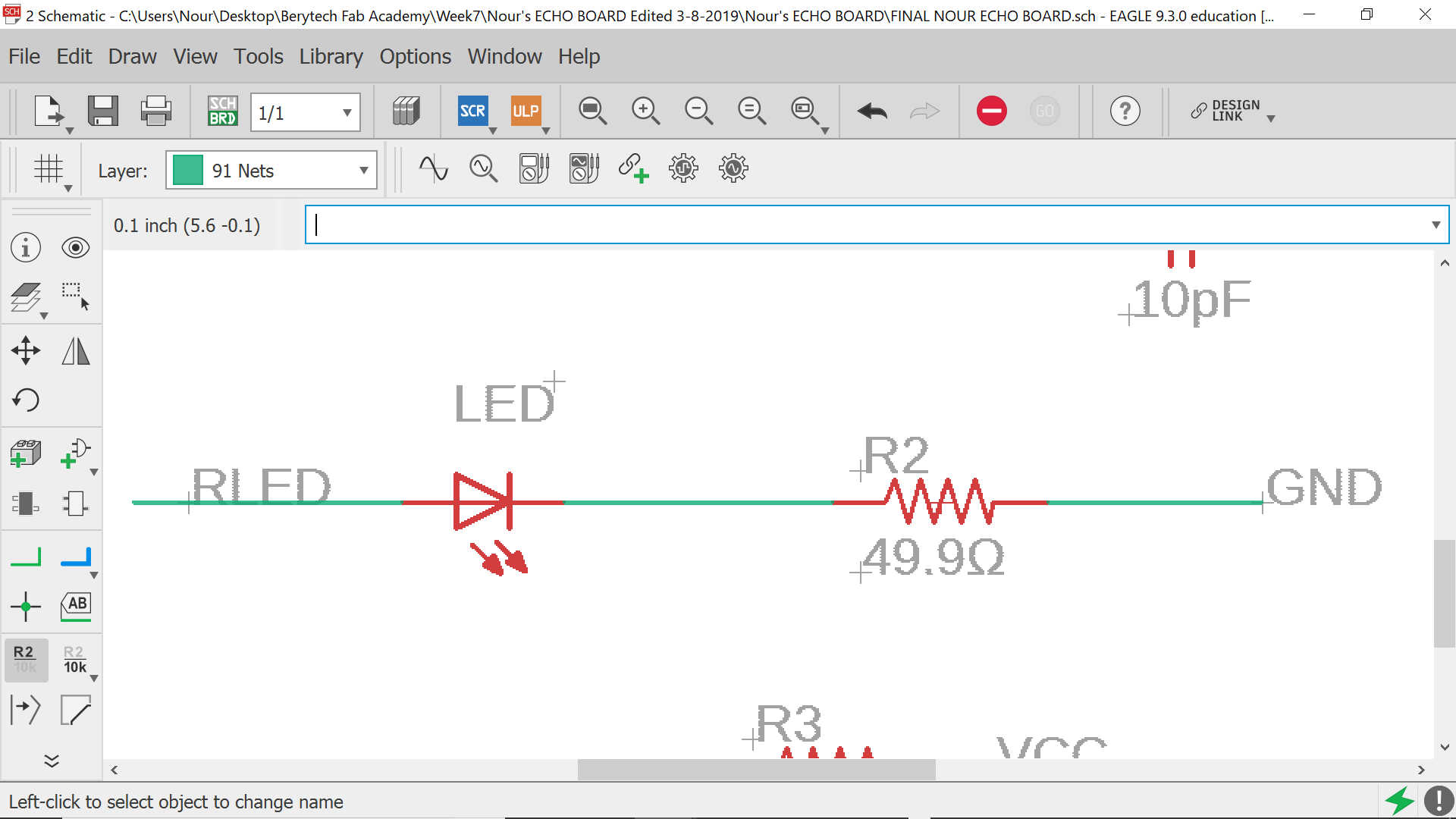
And according to the green LED datasheet, and as per the below equation, we can calculate the resistance needed and which is 40Ω. The closest number available at the lab is 49.9Ω.

And finally and according to the push button datasheet, the resistors needed are 10kΩ for each button.
Now you have your schematic ready
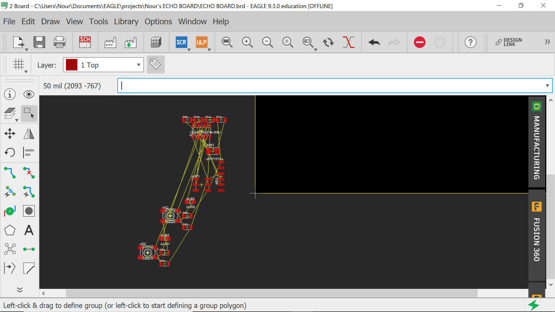
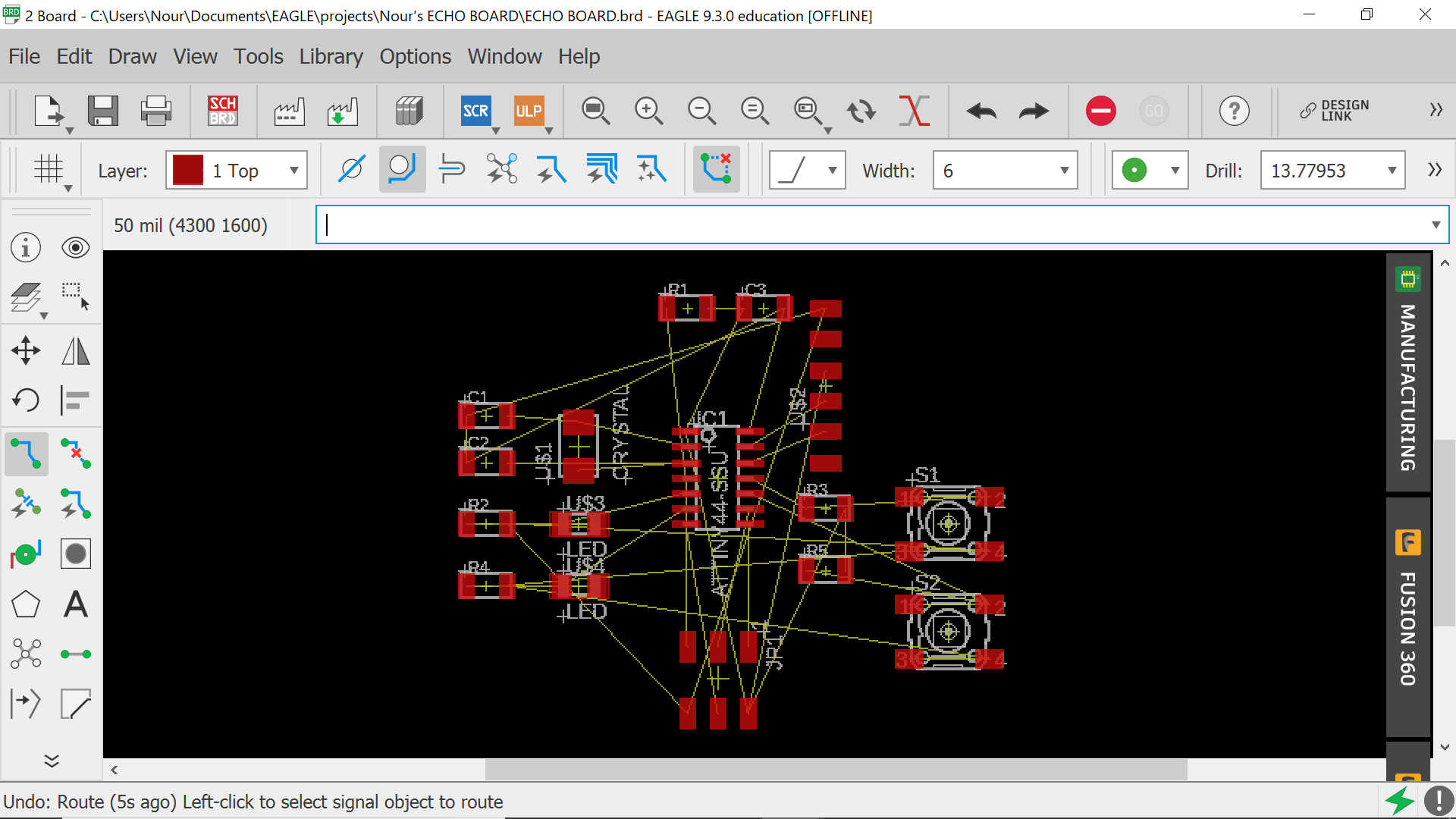
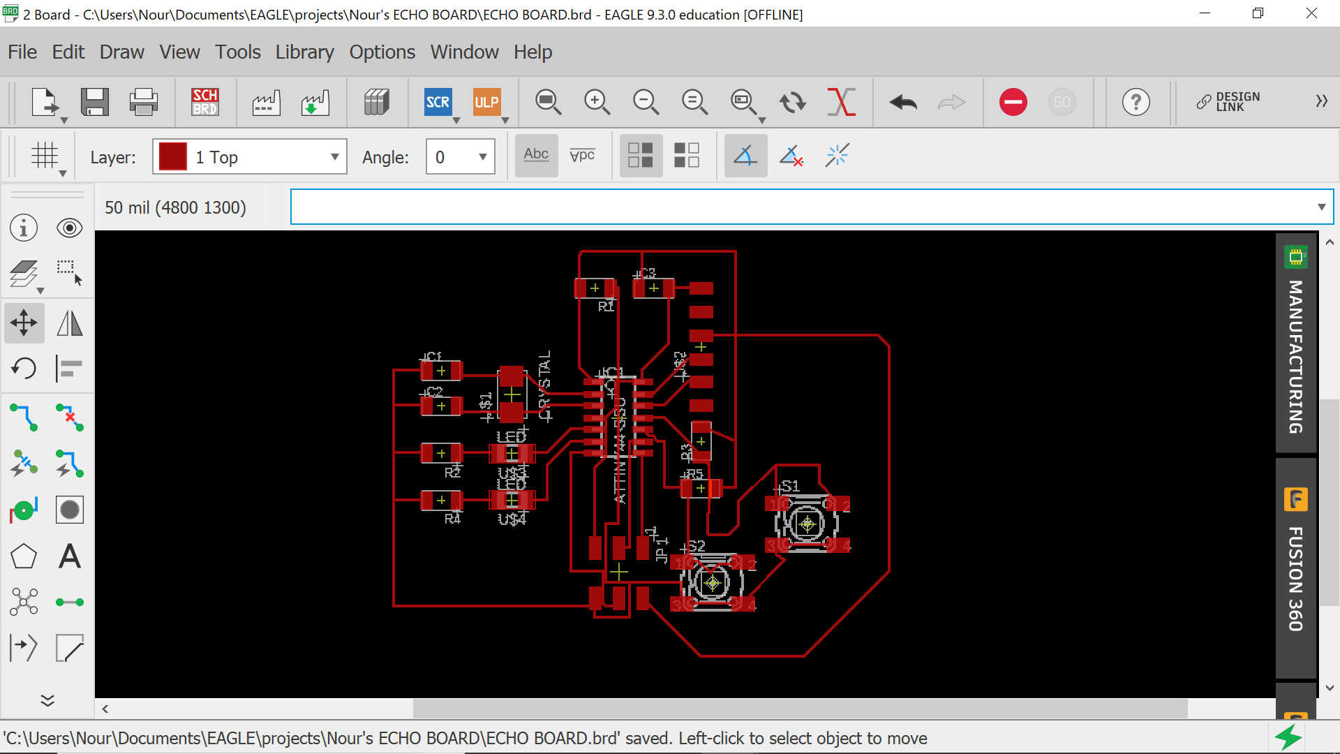
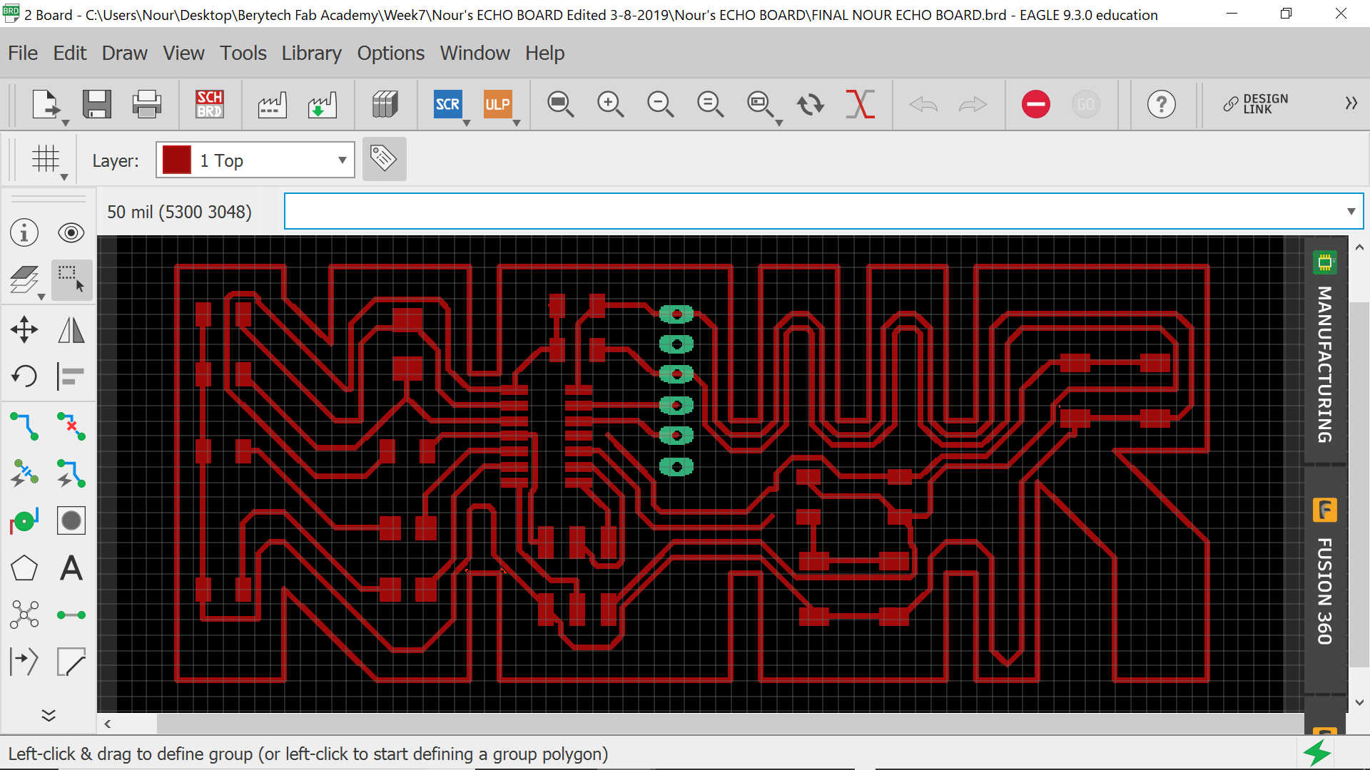
The next step is to generate the board and complete the needed basic wiring by moving the components into the frame and drawing the ROUTES as per the below:
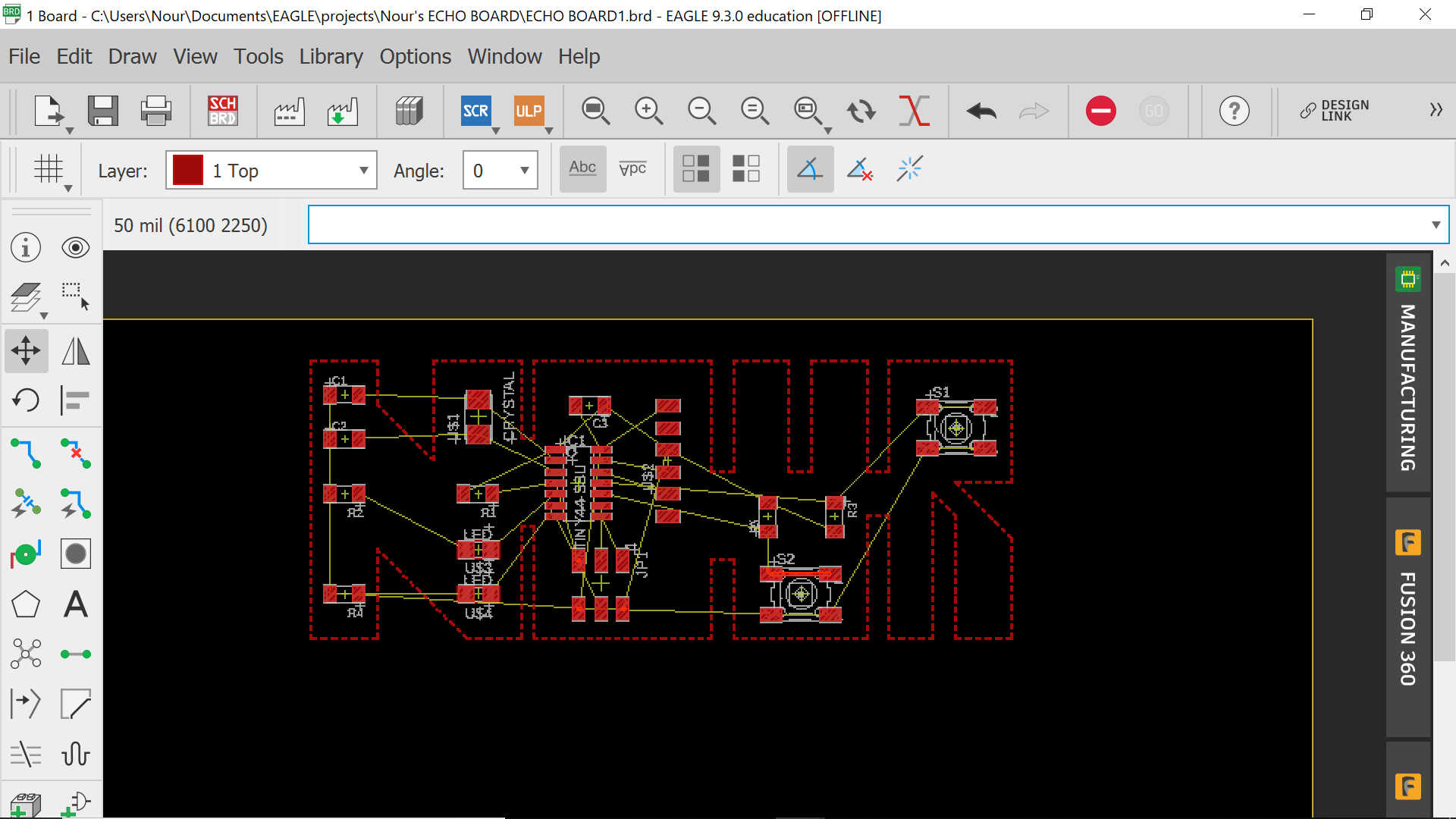
And now is the time to change the board from its basic shape to the shape of my name NOUR
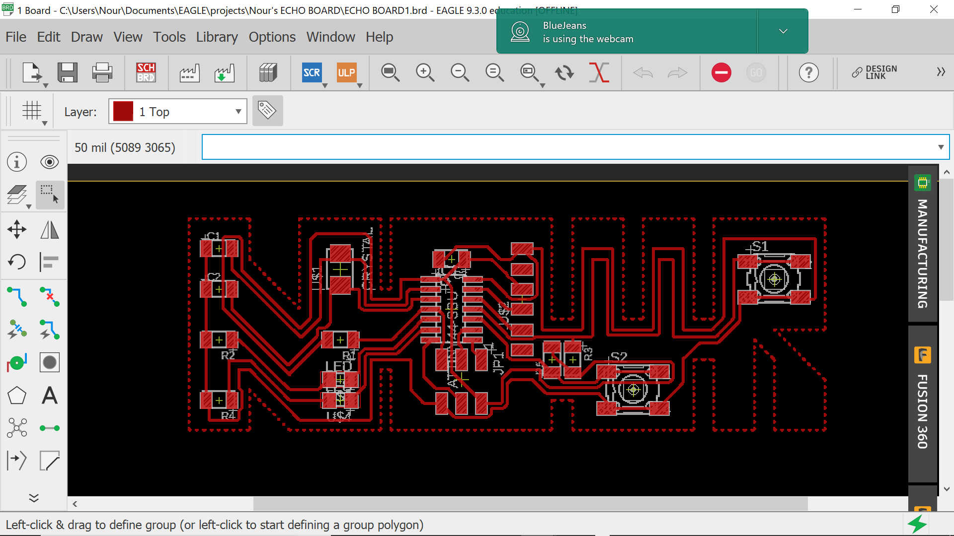
Until I realized that the FTDI I am using from the library is the wrong one and that I should be using the one with the holes
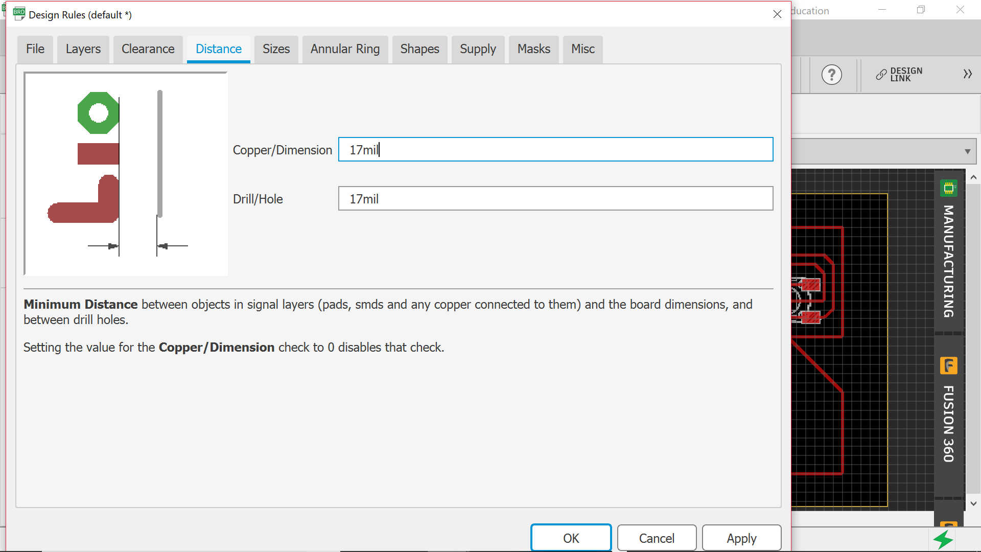
And later I have realized that I need to change the design rules for my board as per the below:
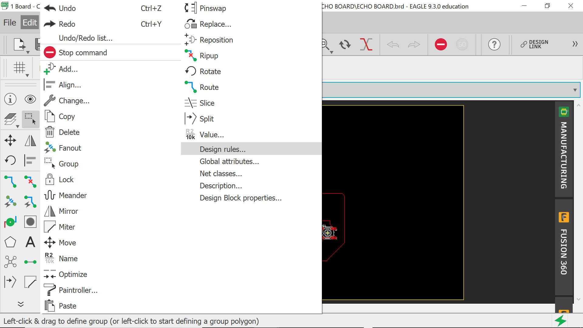
You will need to change the clearance, distance and size
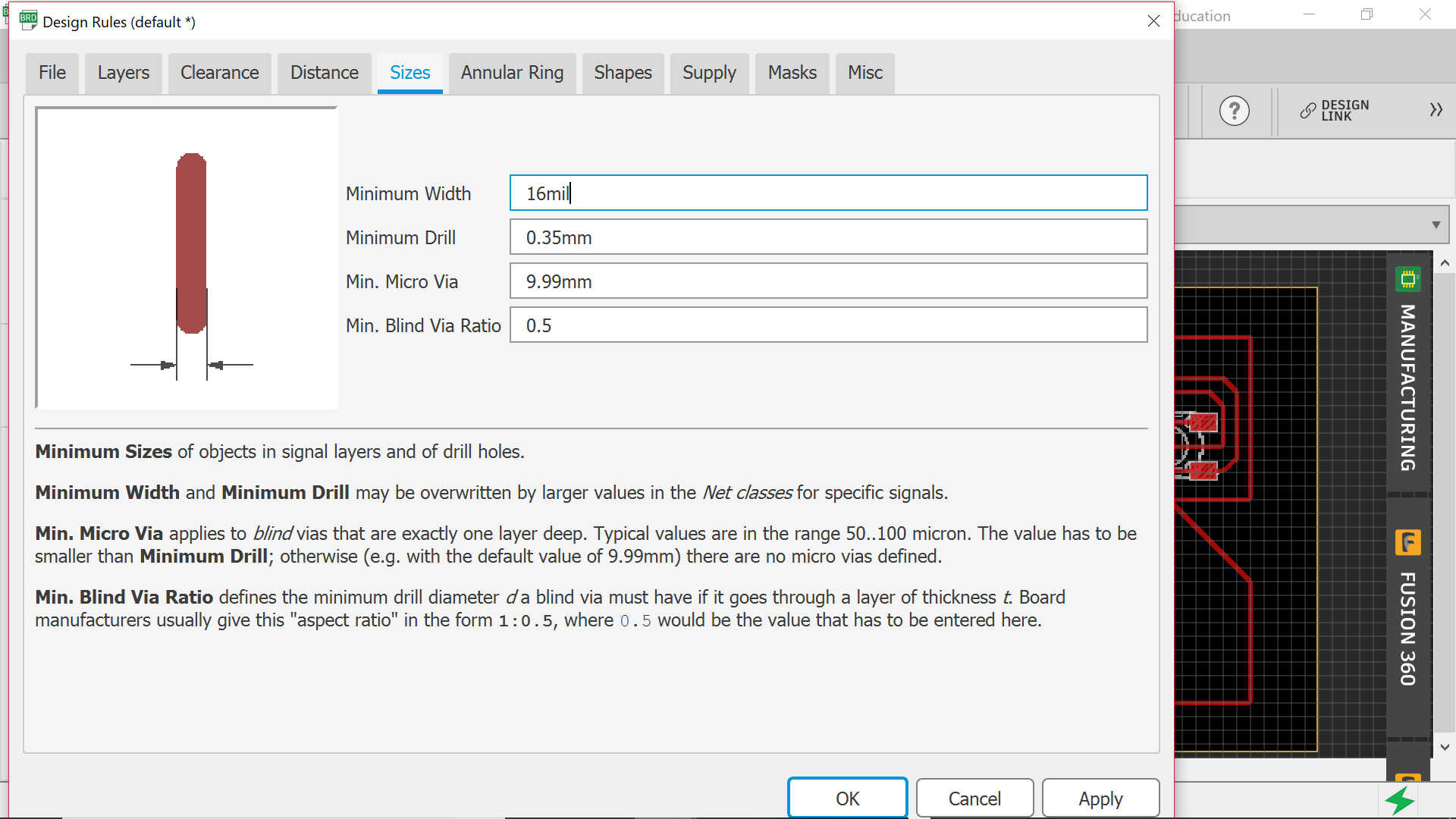
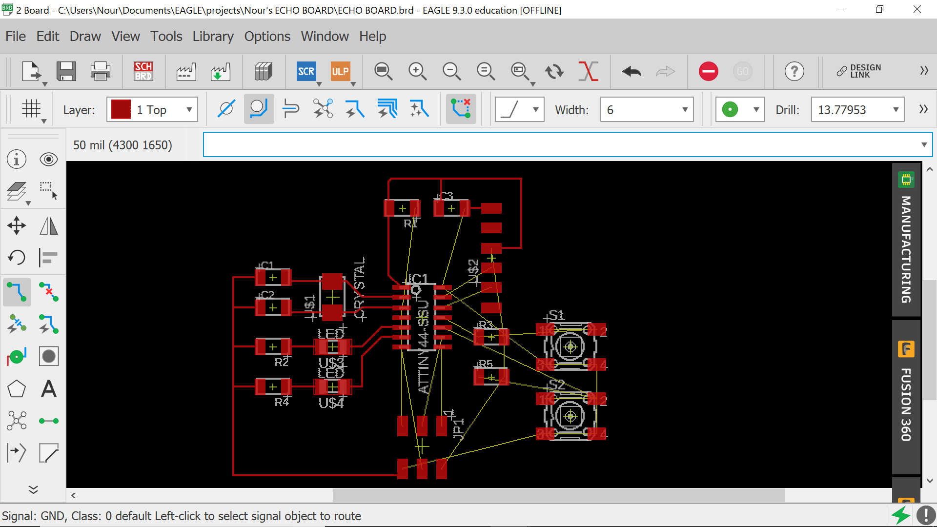
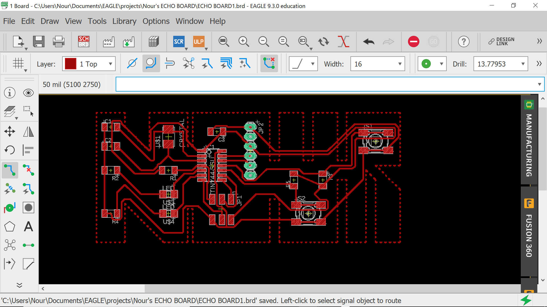
What happened here is that the routes I have previously drawn are not fitting between the components when I changed the design rules. Therefore, I had to place a 0Ω resistor in order to connect VCC together and GND together
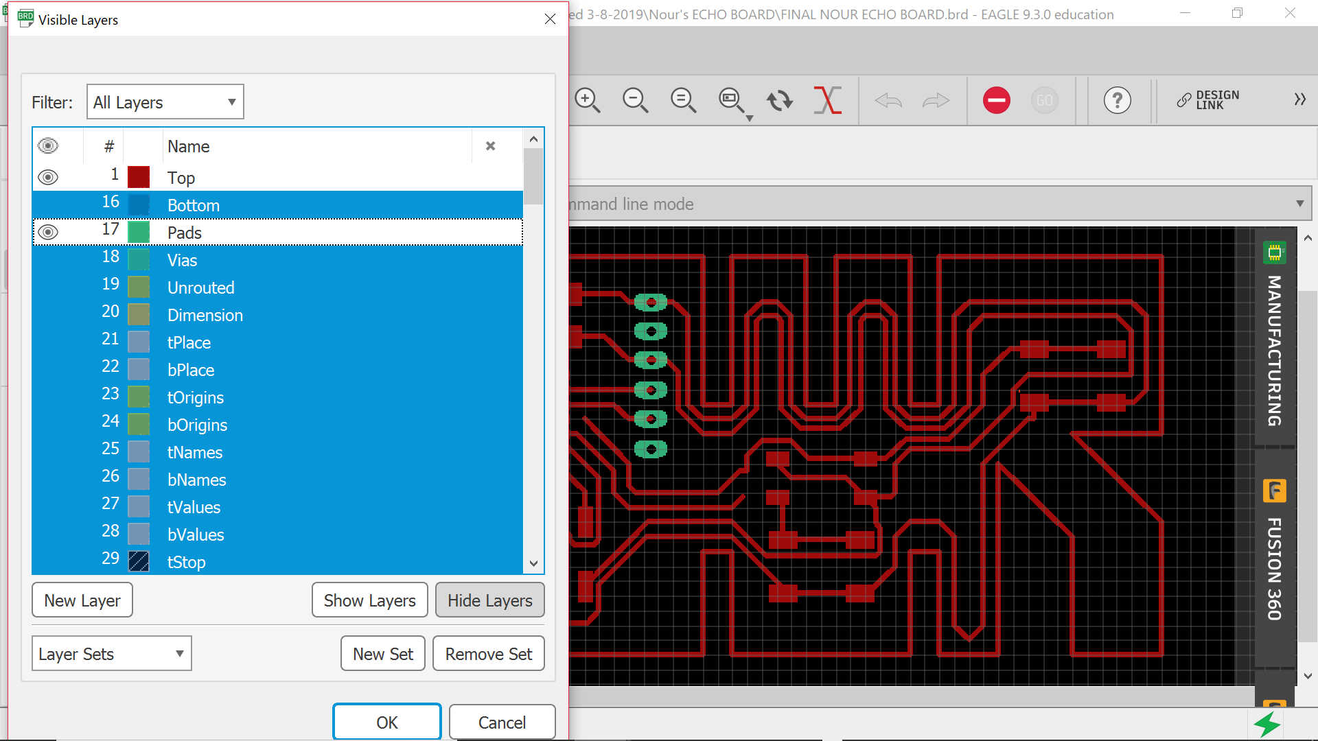
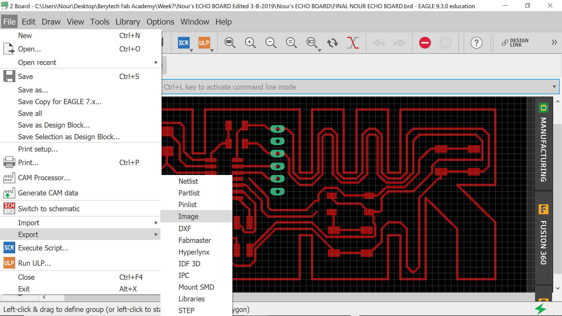
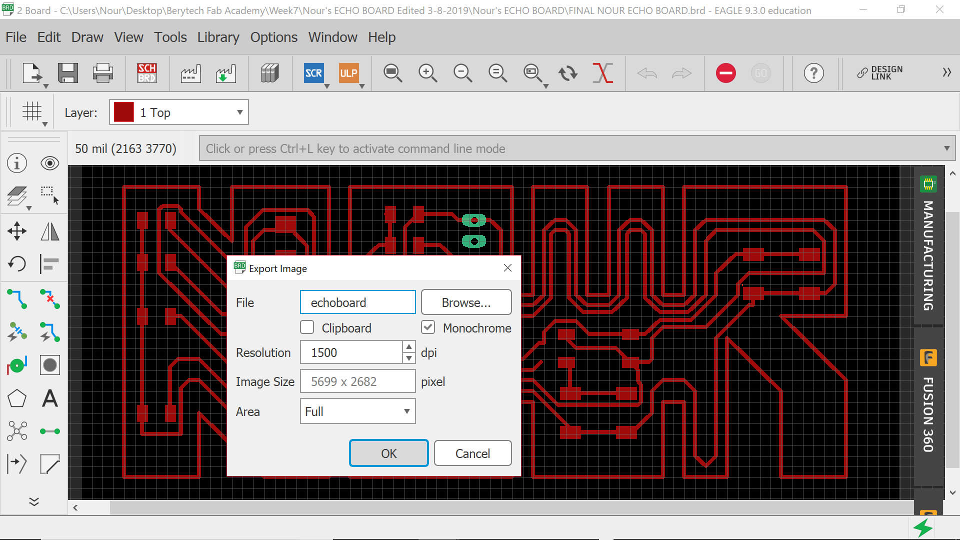
Now is the time for exporting the image. Before doing so, you need to turn off all layers and keep the one of the top and the pads on
Then export the image and make it monochrome (so you can have it in black & white) for generating the G code needed for milling. You also need to put the resolution as 1500 dpi
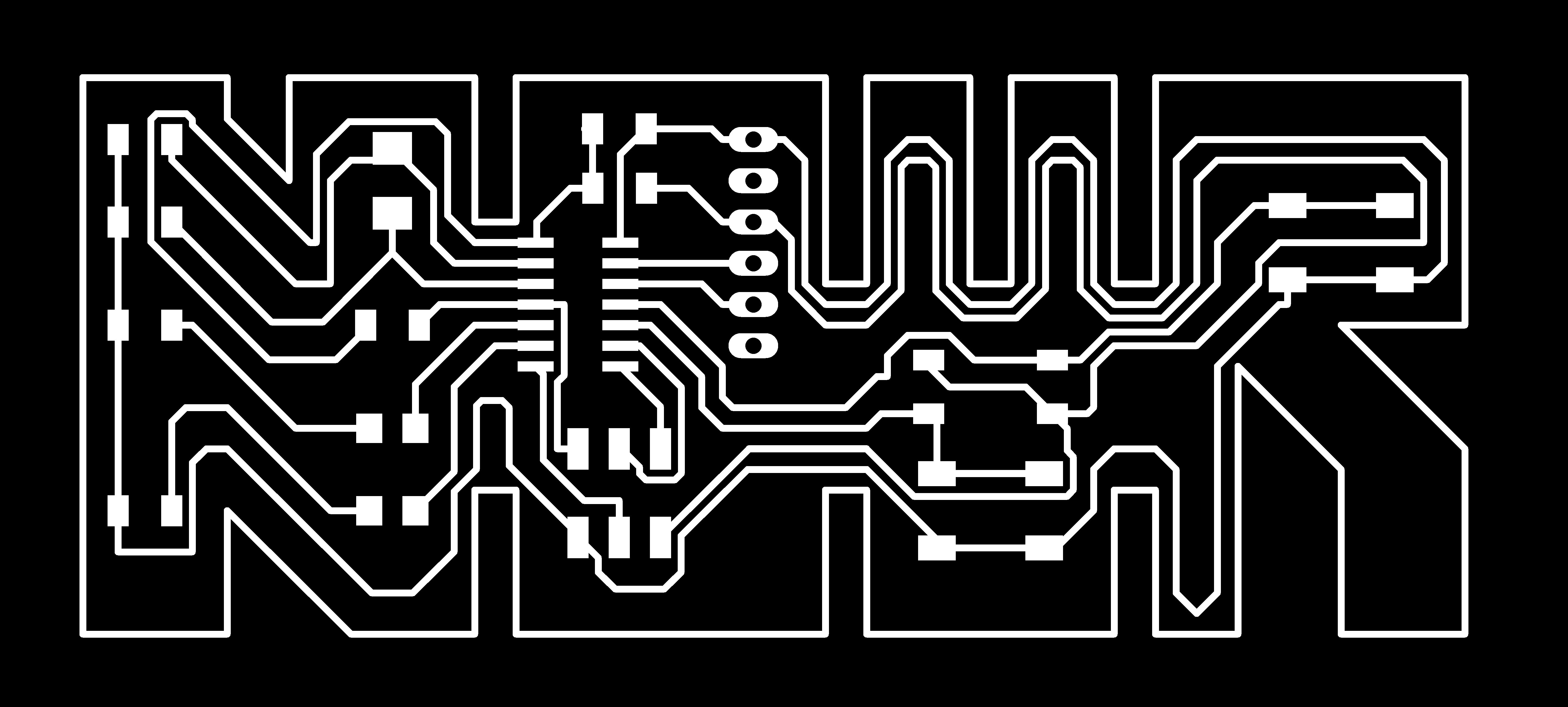
So you may get the final below image:

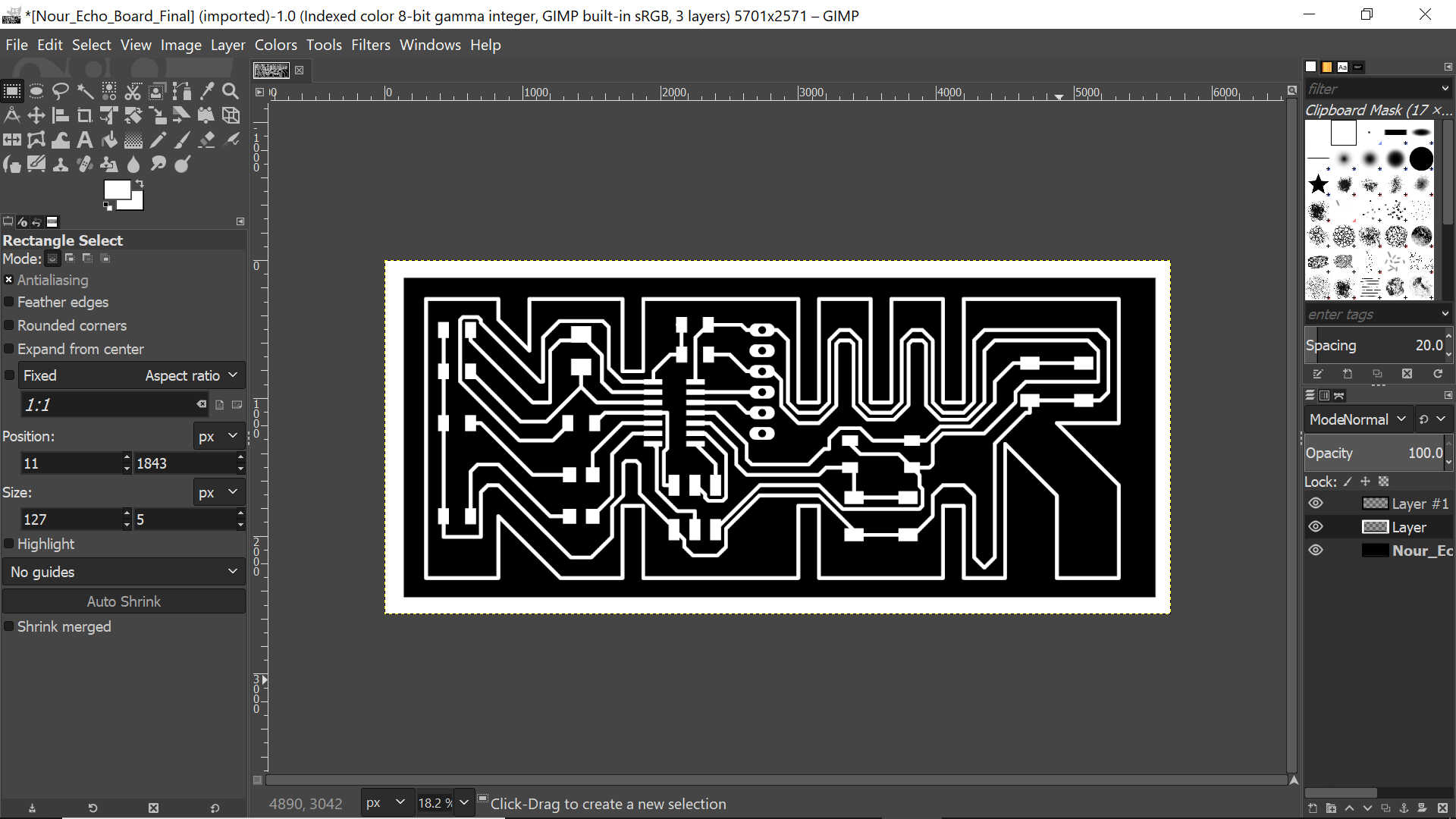
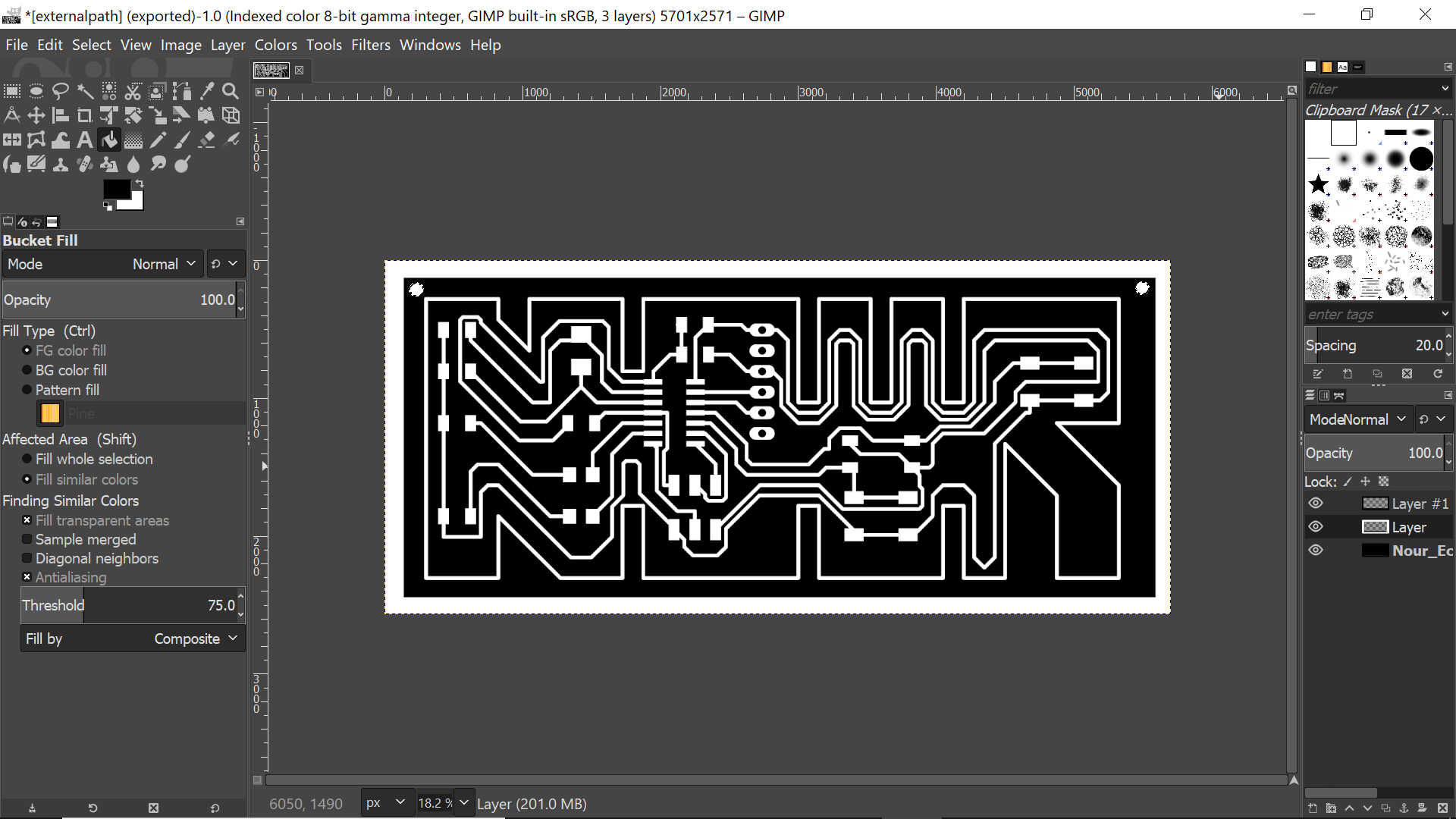
Which you need to edit on GIMP in order to get the internal and external path and the holes:
Internal Path:
External Path:

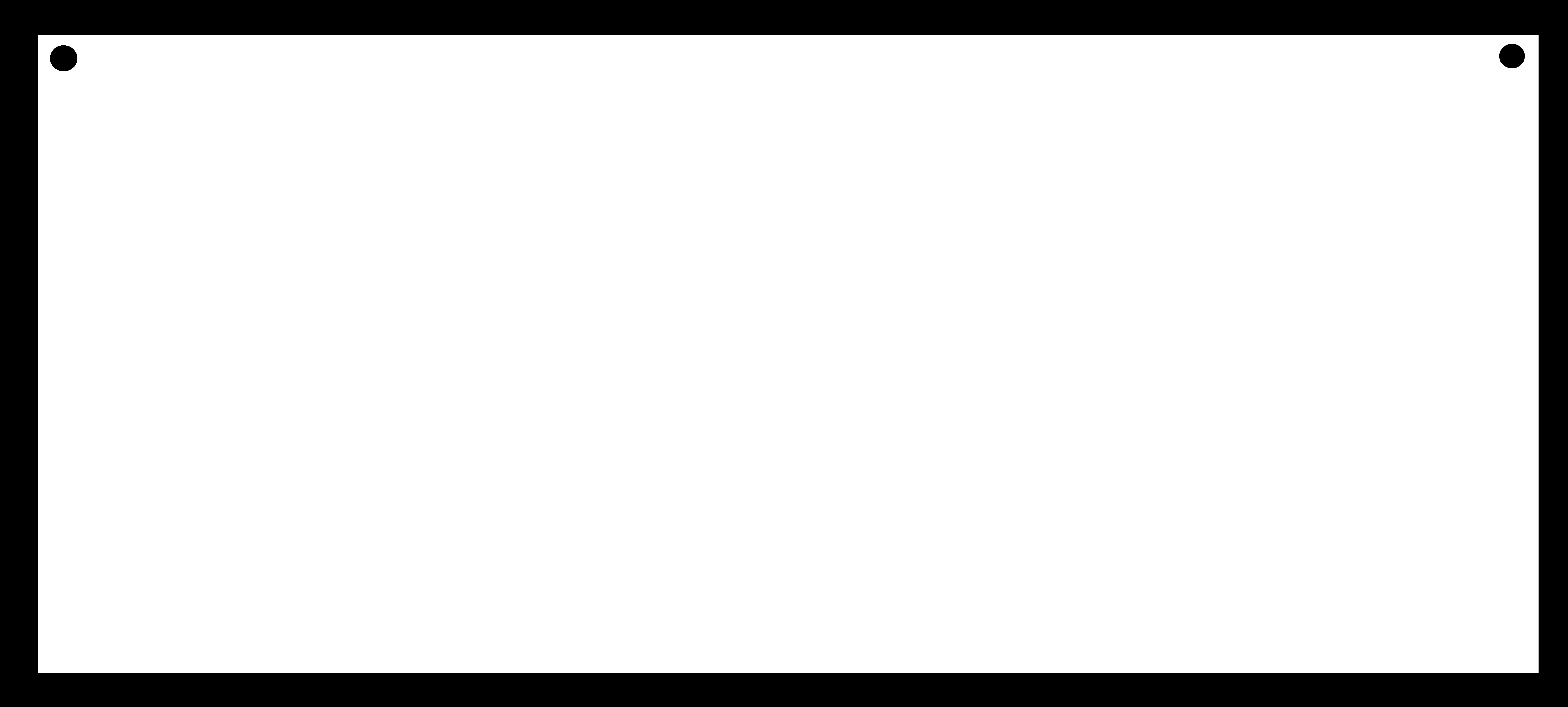
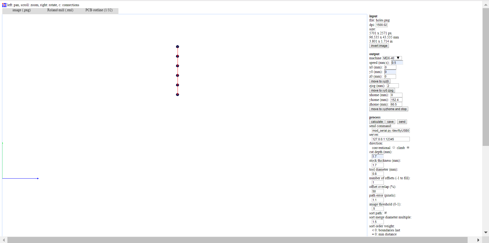
You may notice that I have added two holes on the external path to be drilled so that I can wear my board as a necklace!
Holes:

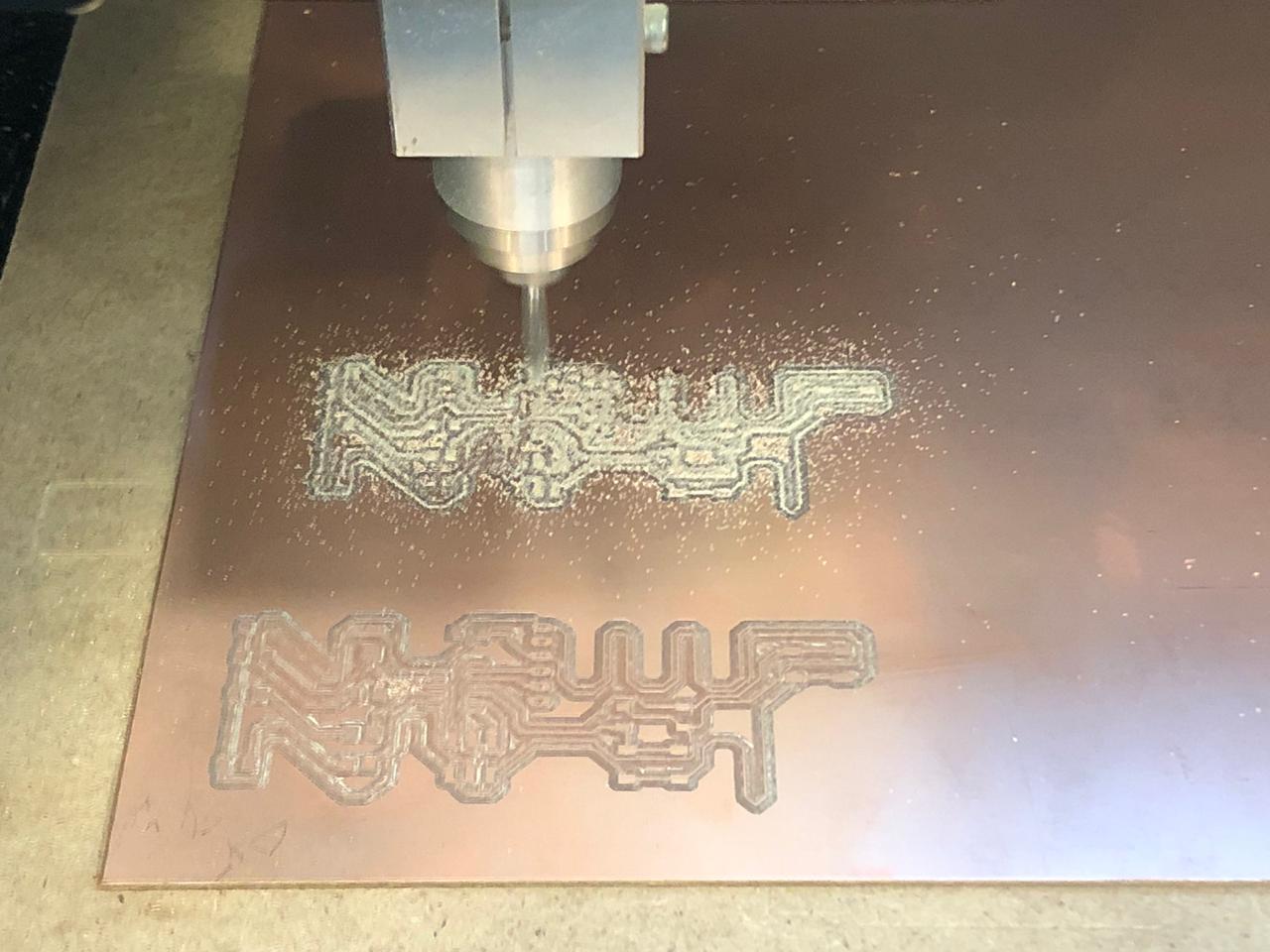
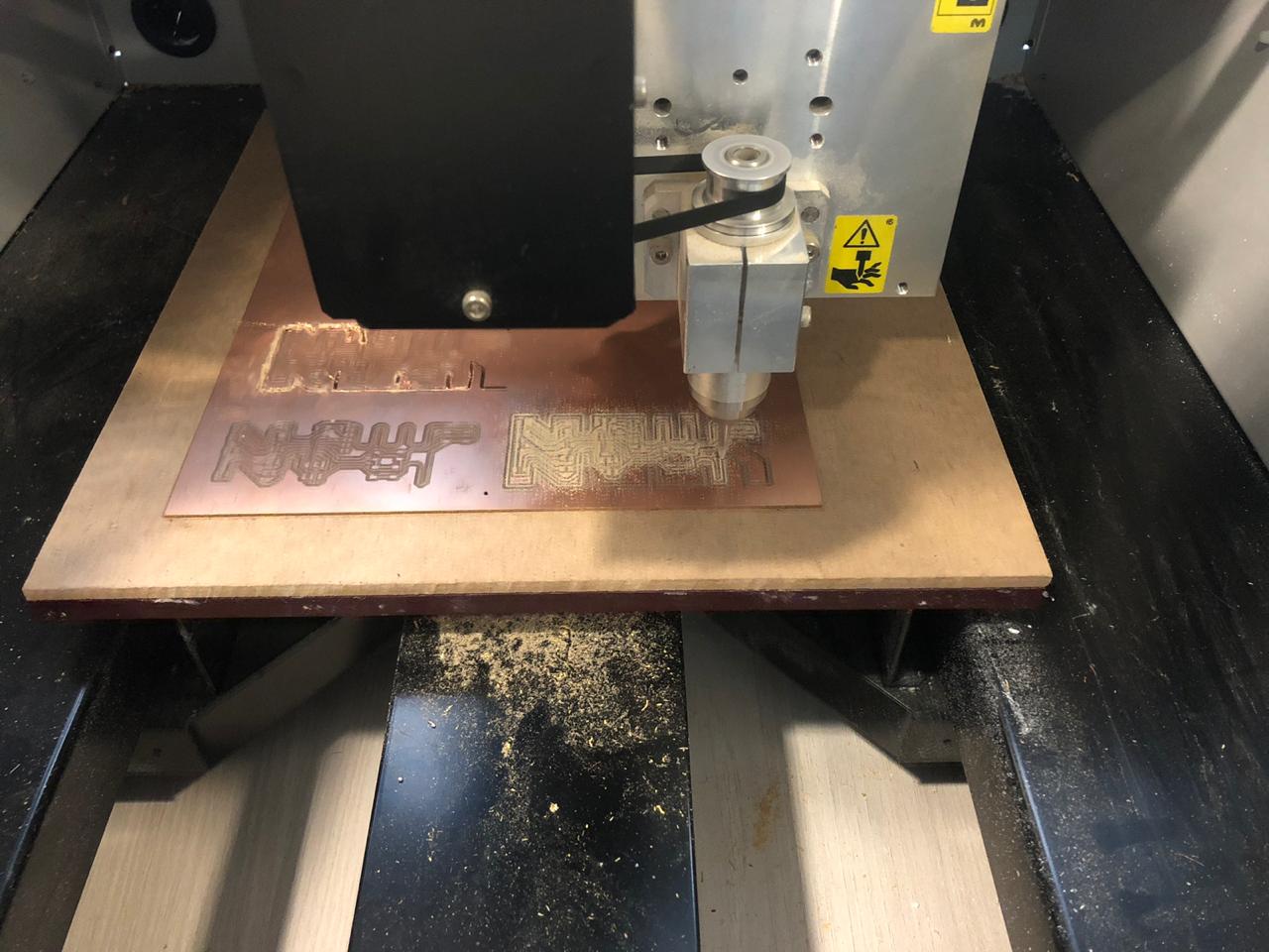
Then generate the G code for milling
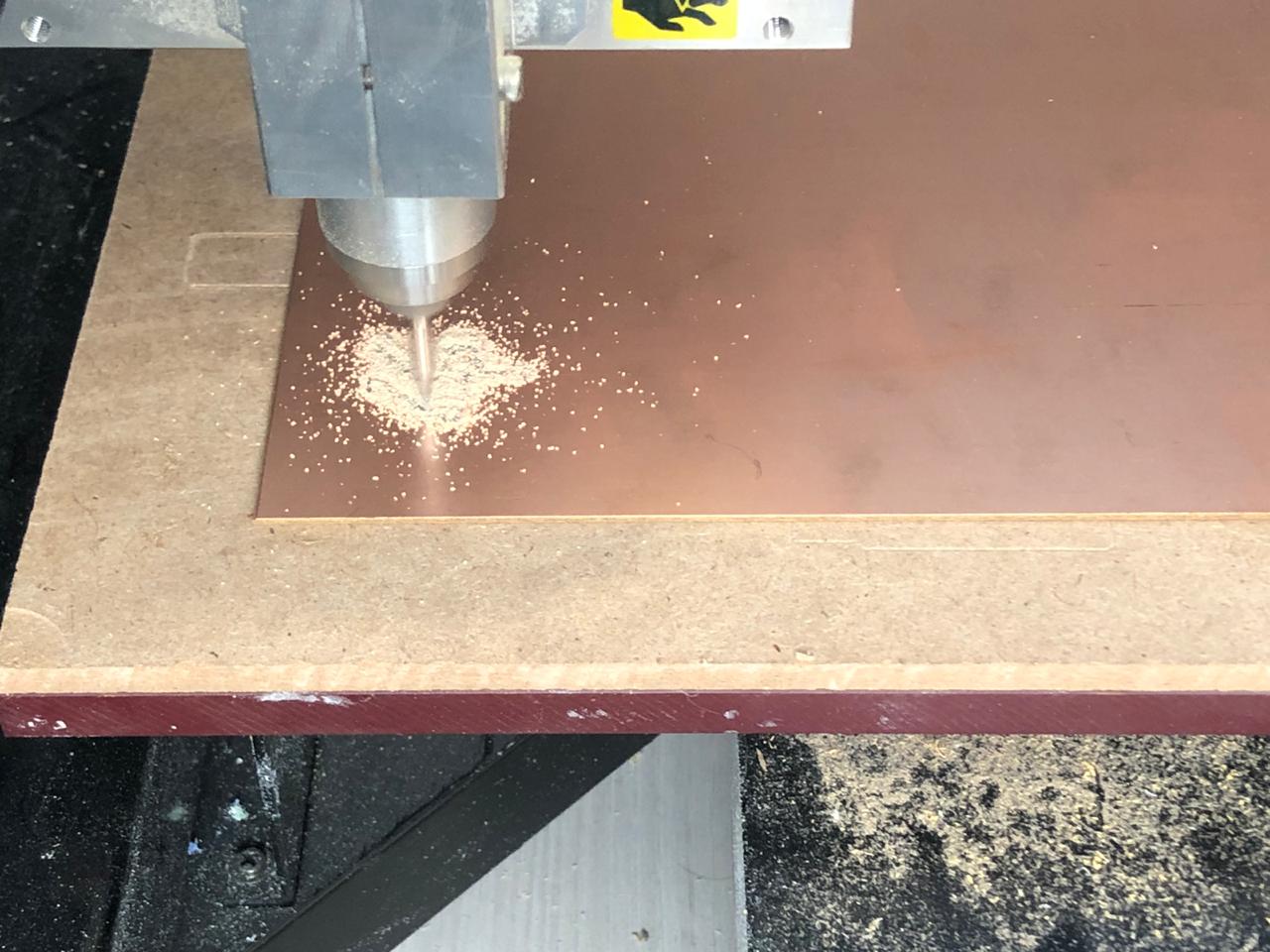
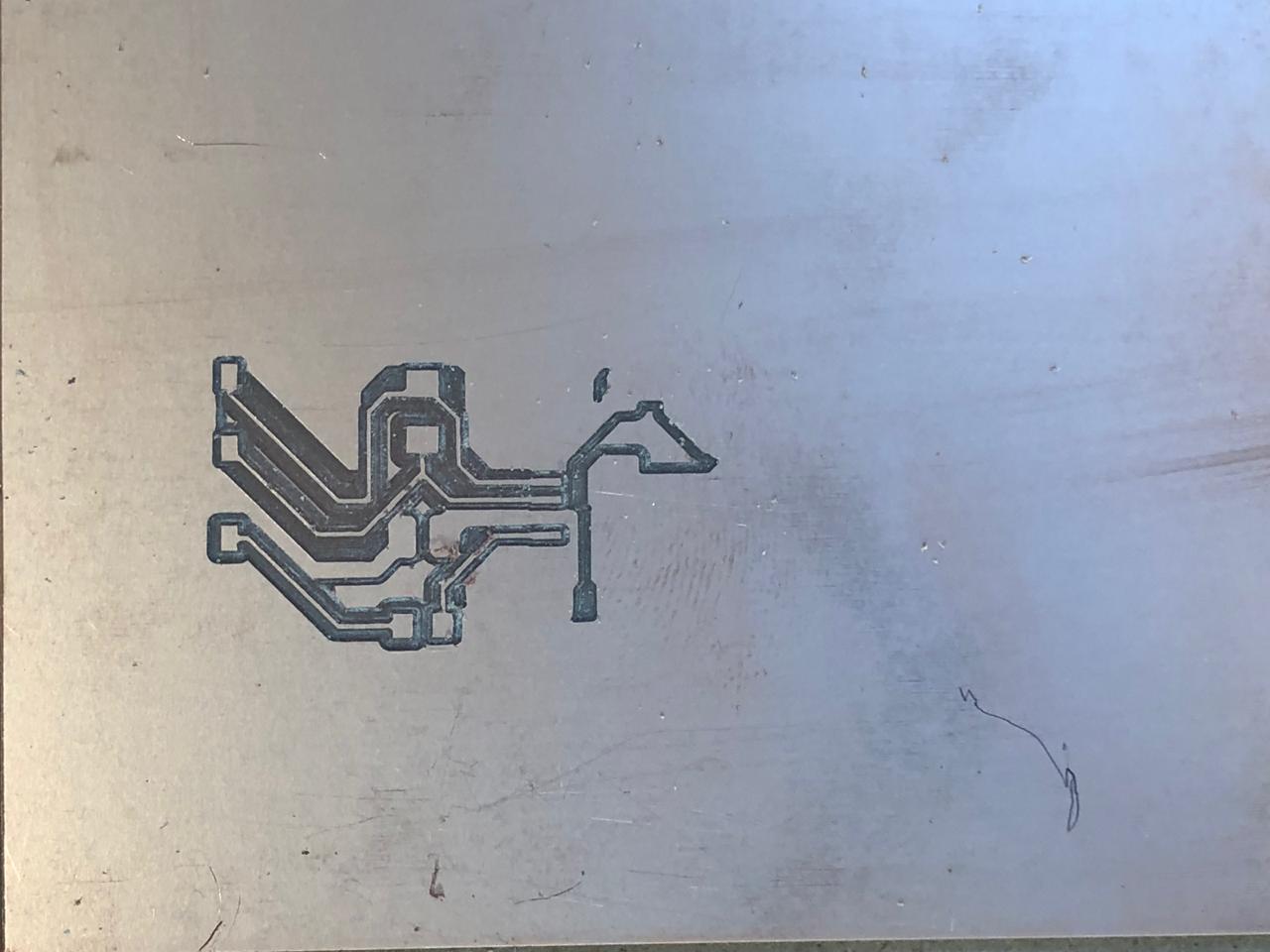
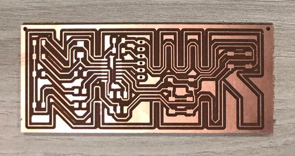
Unfortunately, the first trial went wrong because there was a line that was not milled by the machine. So we had to do another trial
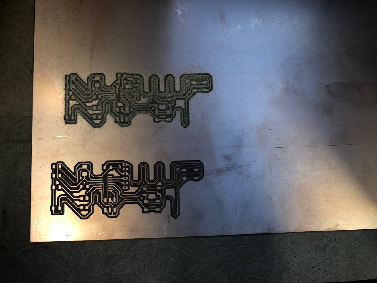
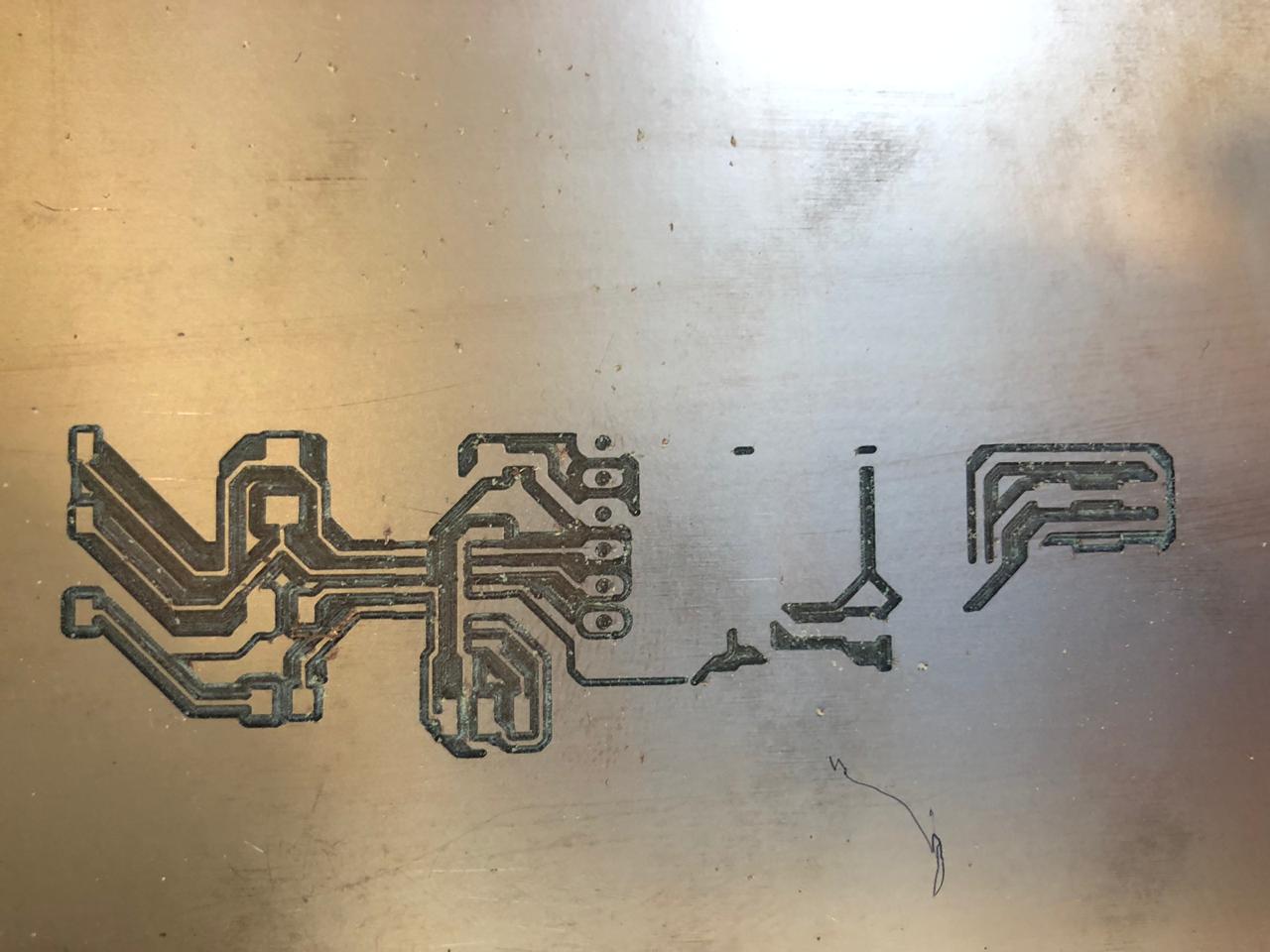
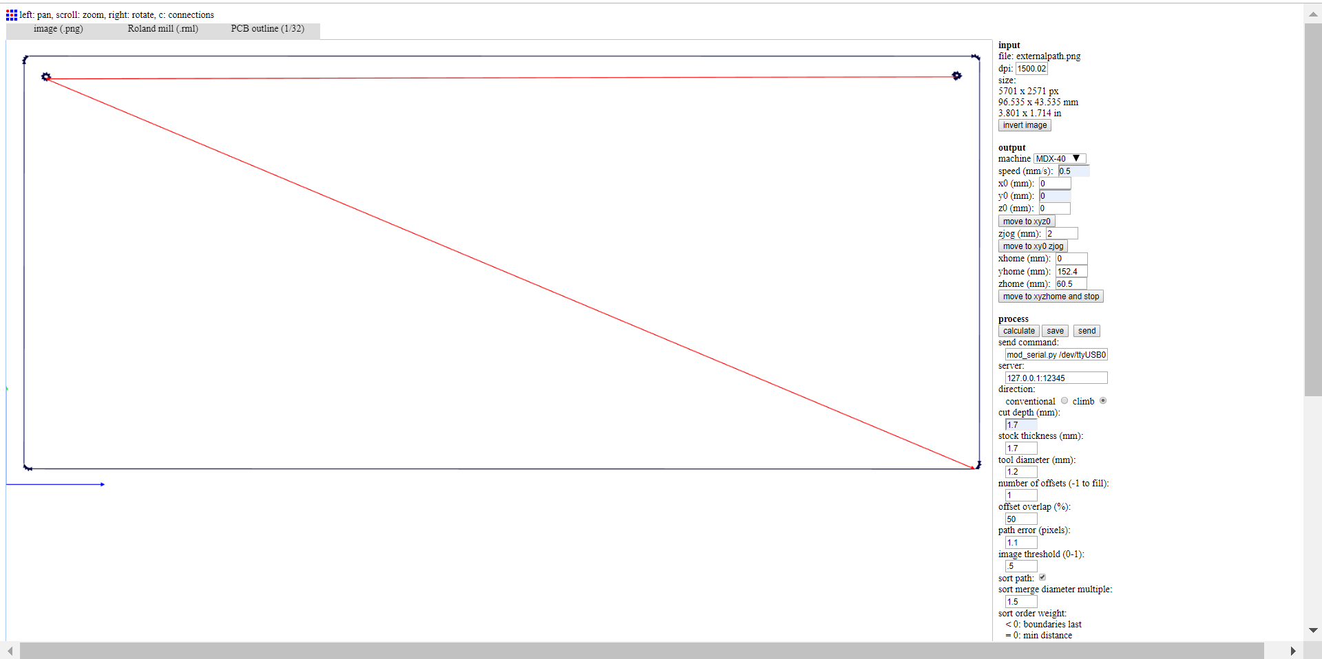
And as you can see in the photo above, the external path had ruined the whole board because the spacing between the letters of my name was too small for the milling bit that is used (1.2mm). So there was of course a third trial, where I have applied modifications to the external path and drew it as a rectangle that is independant from the letters of my name -which was the best scenario at that time in order to save time. I could have edited the whole board to make the spacing bigger but I ran out of time...
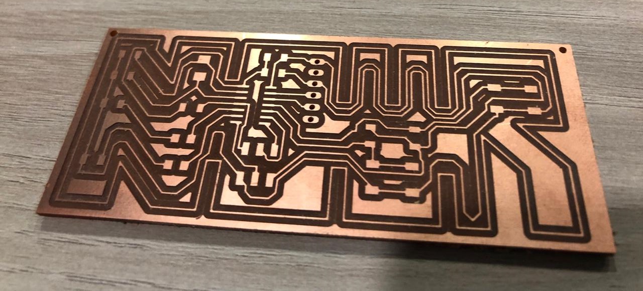
And then we get the final internal and external path, where the shape of my letters is now part of the internal path and the external one is taking the shape of a rectangle as I have previously mentioned above
Final Internal Path:
Final Holes:
Final External Path:
And for generating the G code, the drilling bit for the internal path that is going to be used is 0.4mm, for the holes 0.8mm and for the external path is 1.2mm
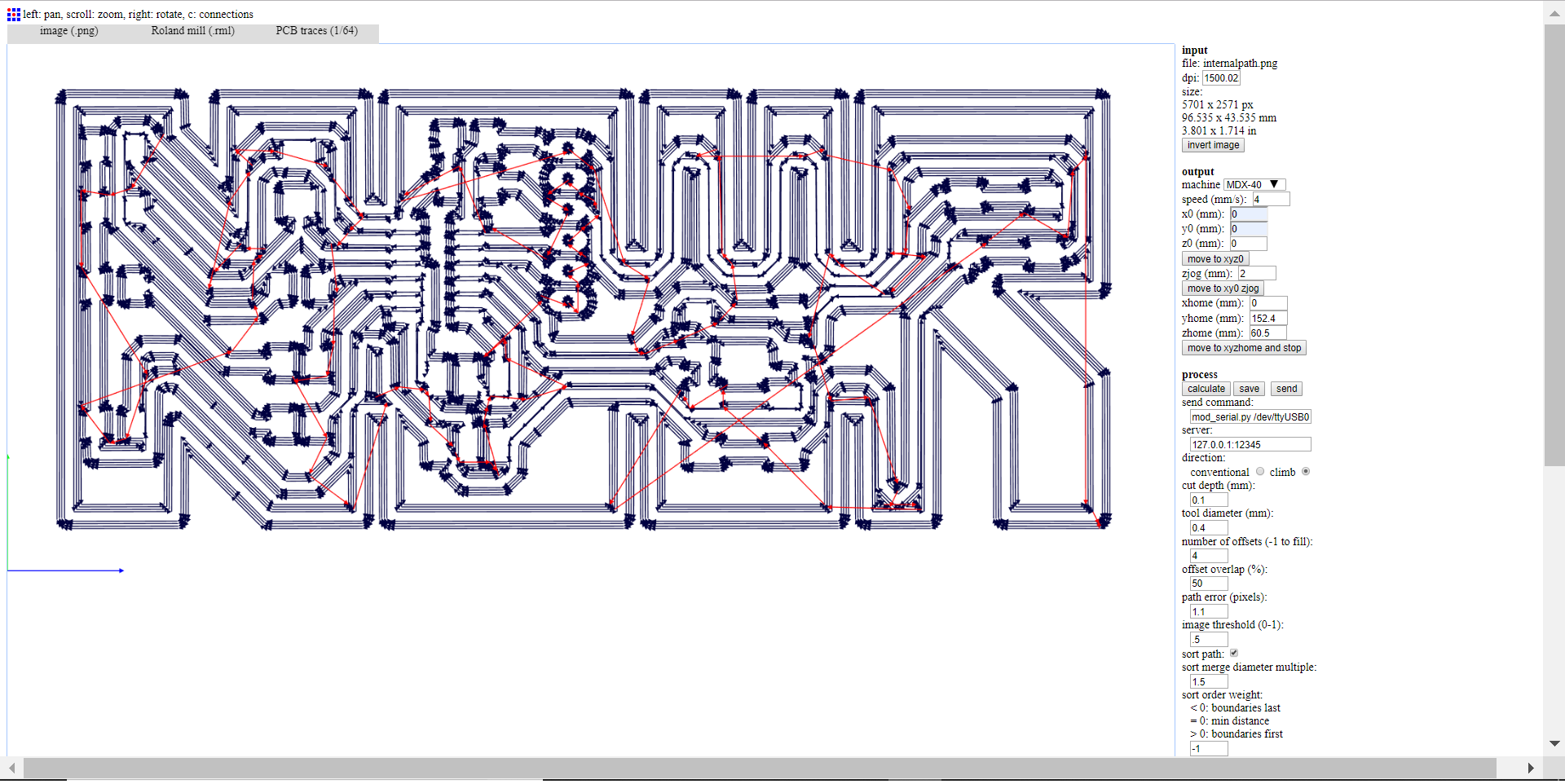
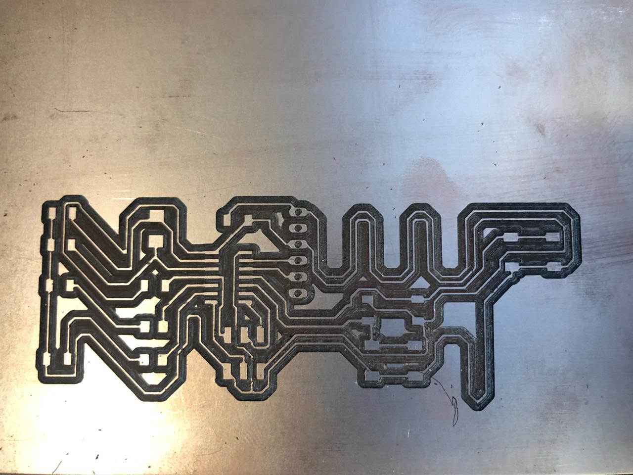
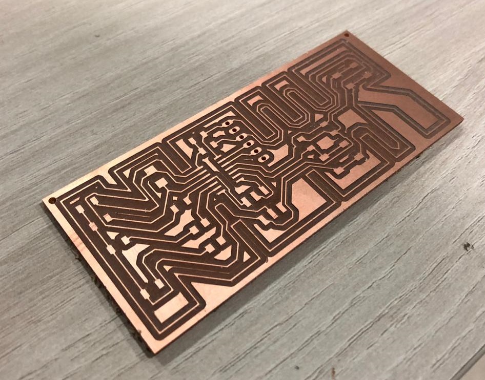
And for generating the G code, the drilling bit for the internal path that is going to be used is 0.4mm, for the holes 0.8mm and for the external path is 1.2mm. And the milling started...
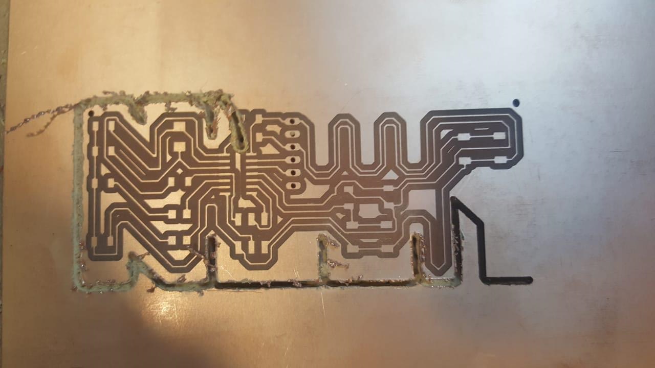
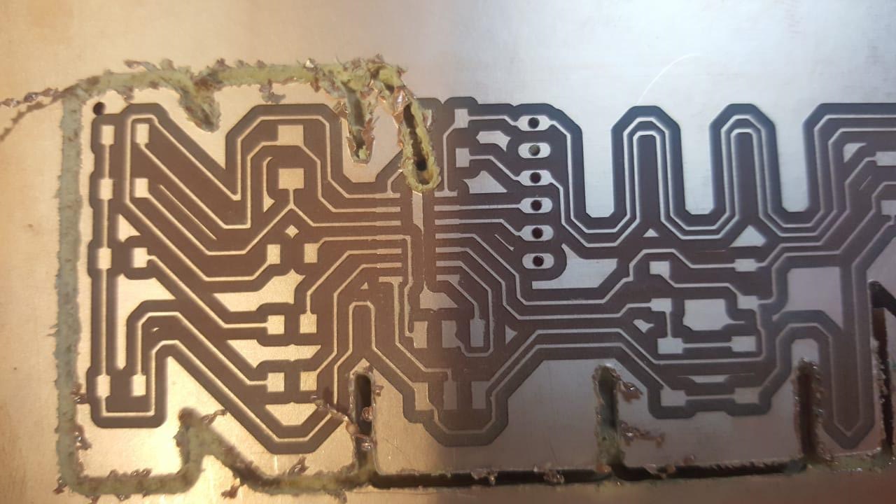
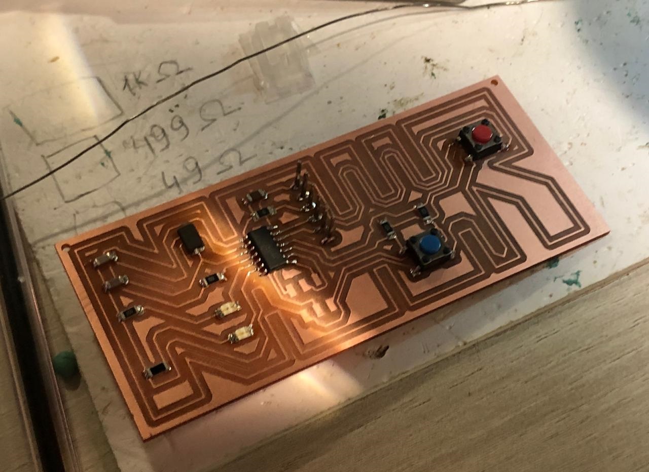
And the final result is...
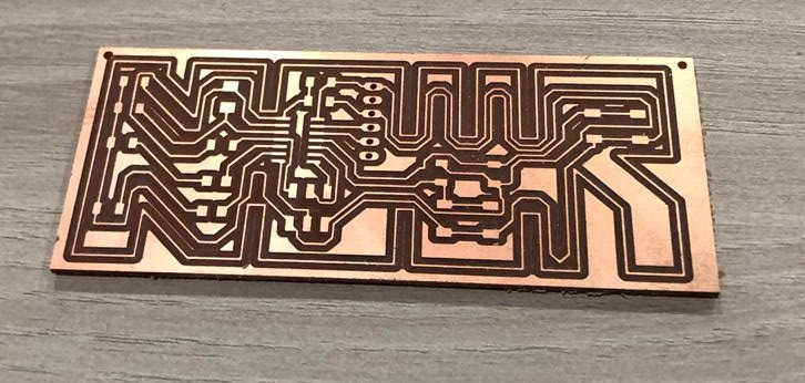
Then you prepare your components and you start soldering...shiny and smooth!
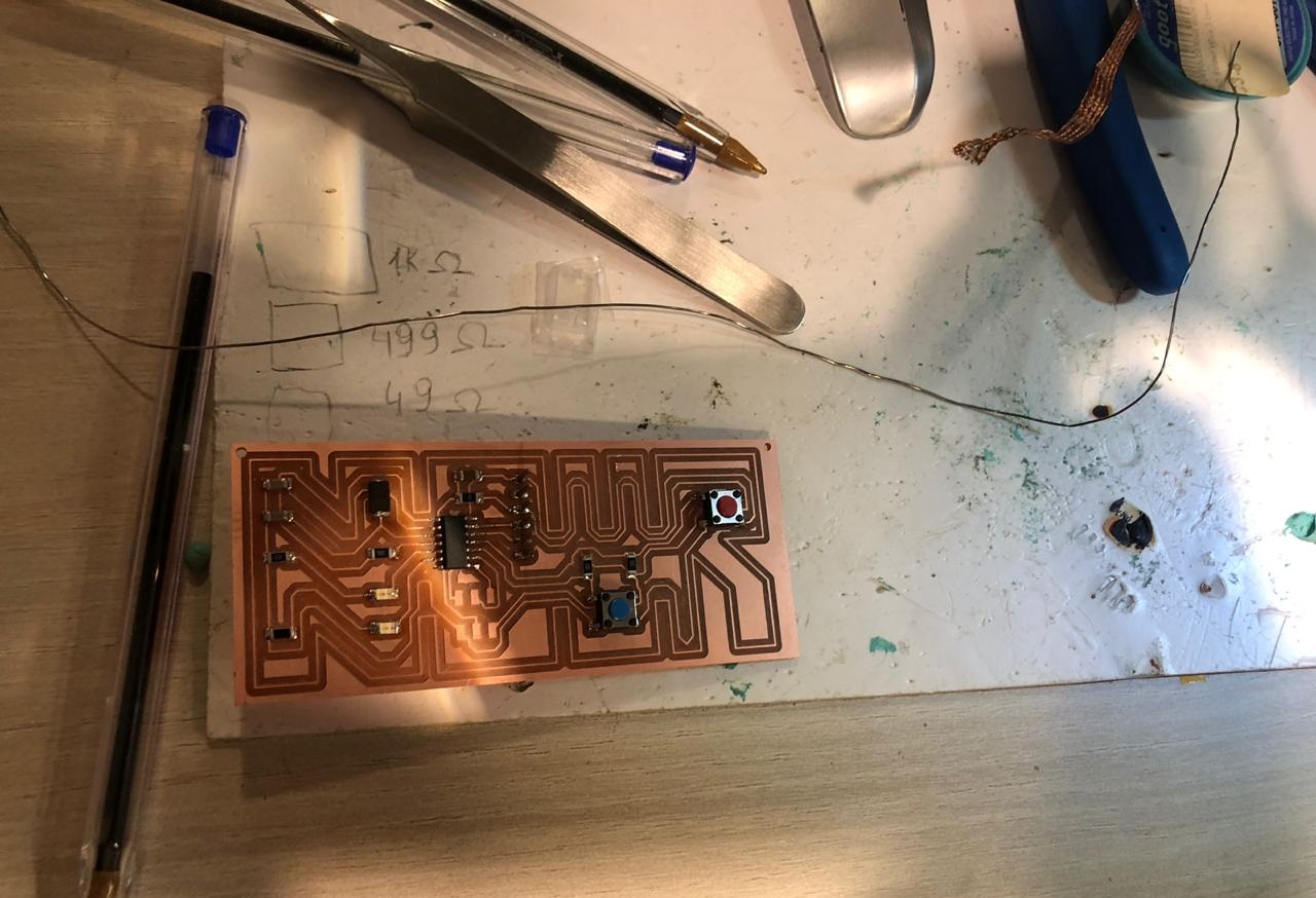
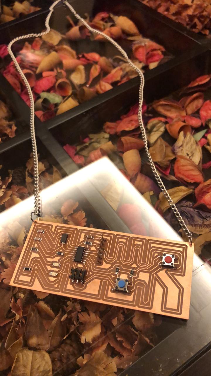
TIME TO GET EXCITED AND TEST THE BOARD!
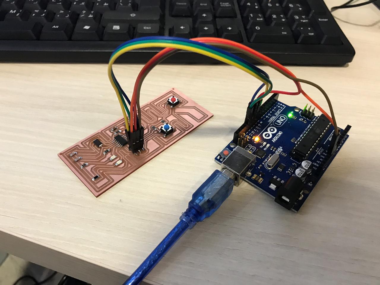
The programming will take place using ARDUINO UNO; So the first thing that needs to happen is to let the Arduino work as ISP so that we can use it to program the board for the very first time
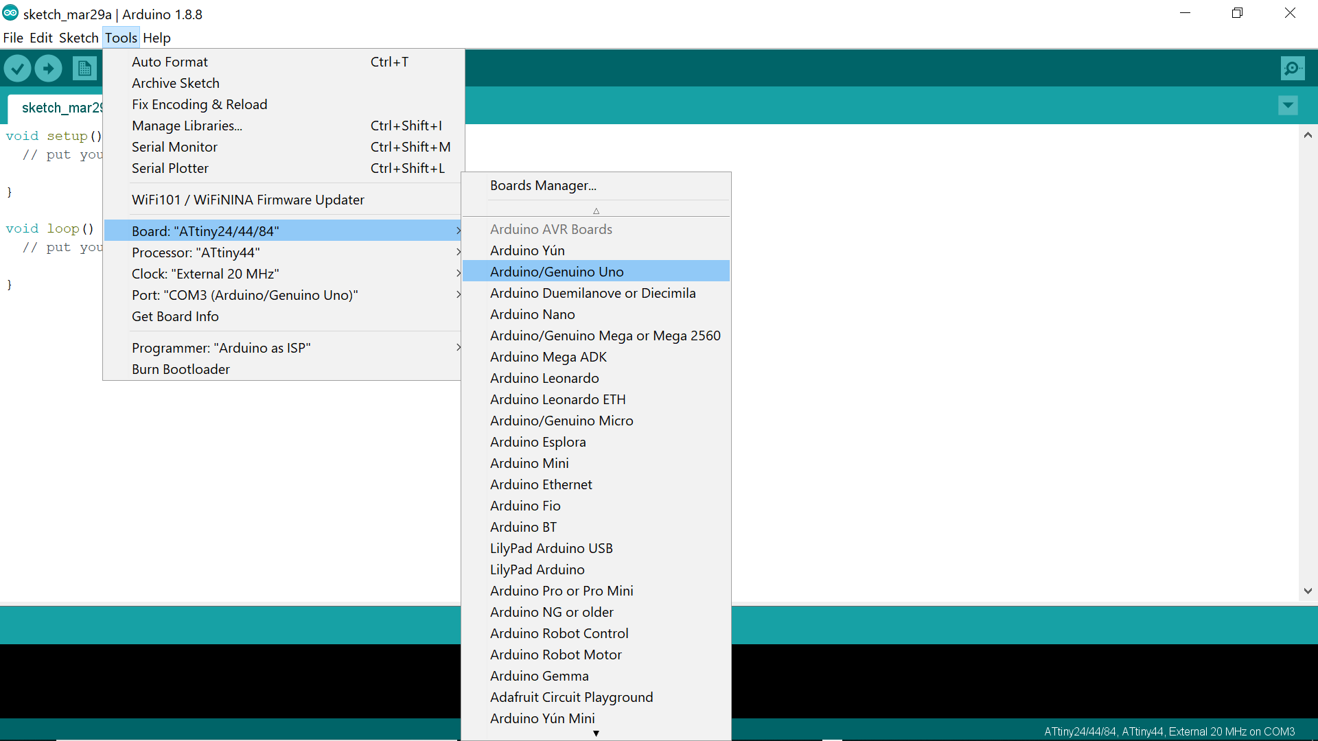
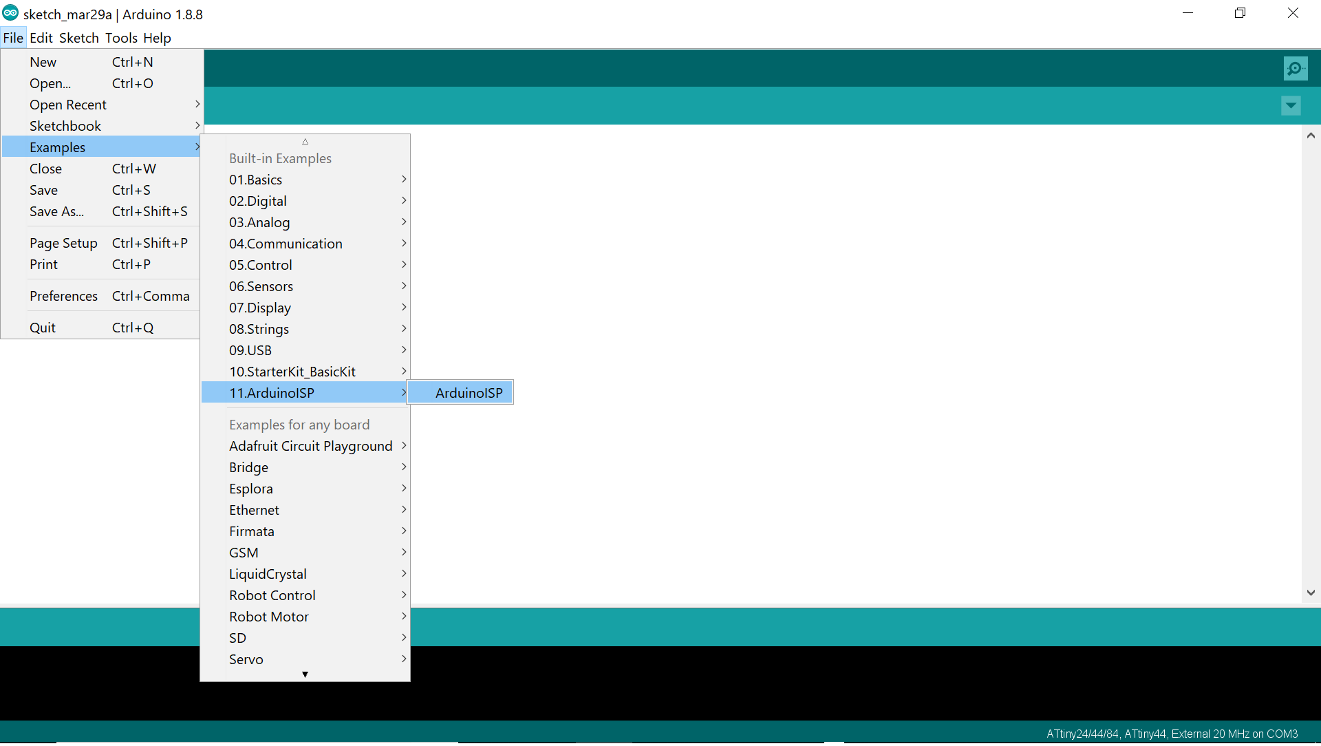
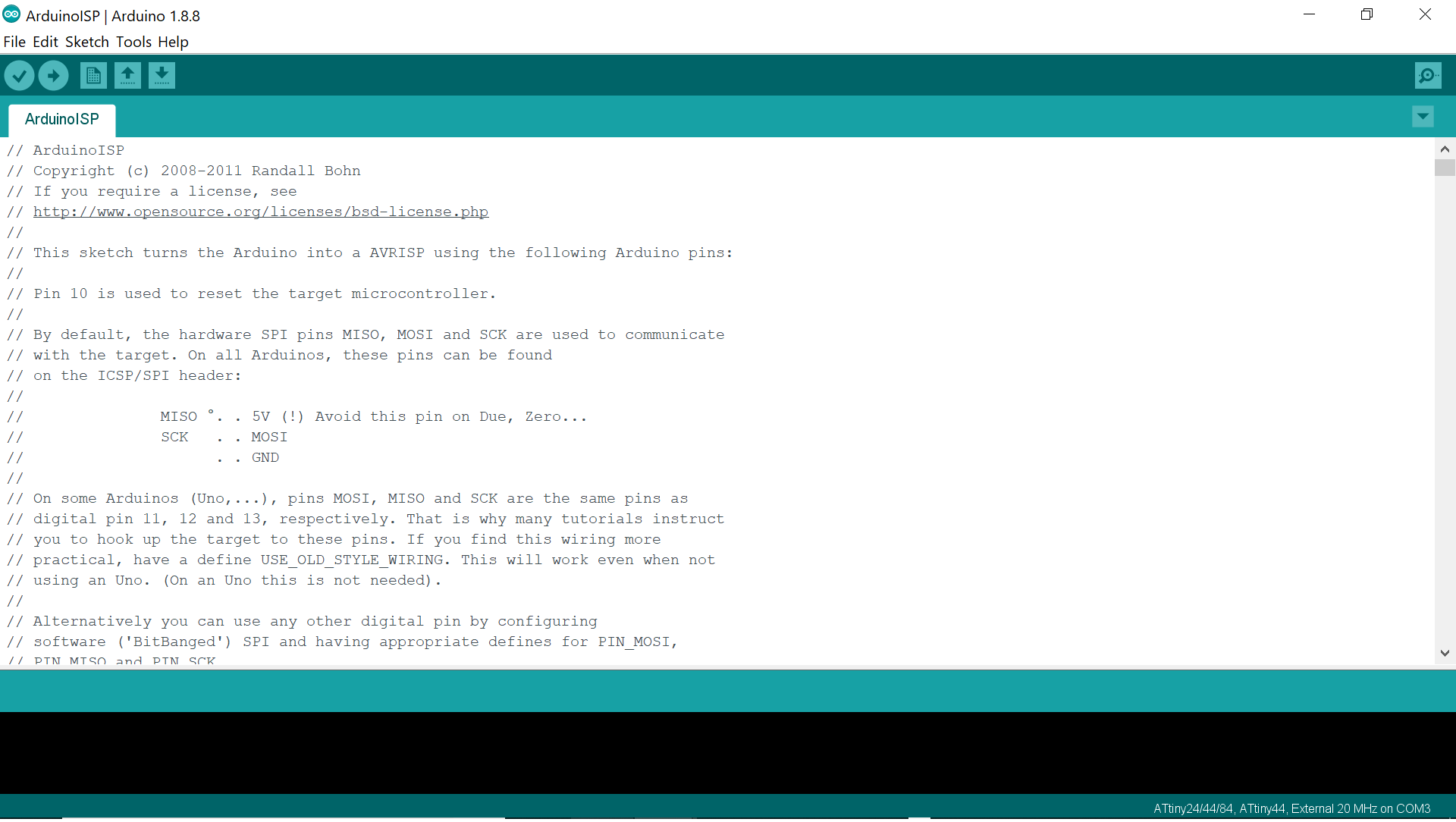
For doing so, we open the Arduino IDE and we connect the Arduino UNO board to the laptop and upload the ArduinoISP sketch from examples to the ARDUINO UNO board all while making sure to select the ARDUINO UNO in boards and the right port as per the below:

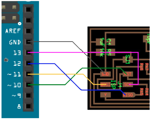
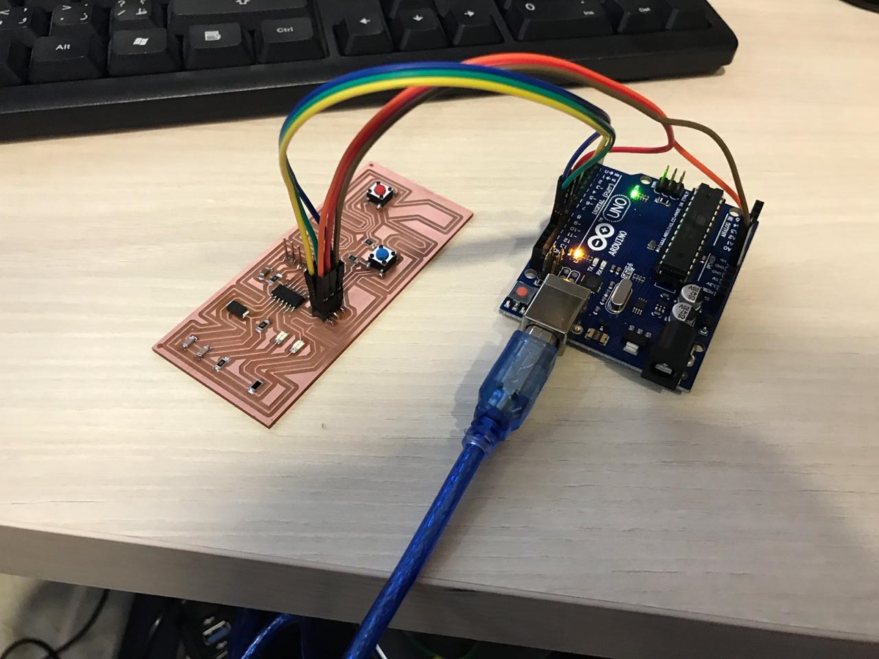
Then disconnect, and connect the hello board to the Arduino board via the ISP on the board following the below schemata and reconnect it to the laptop
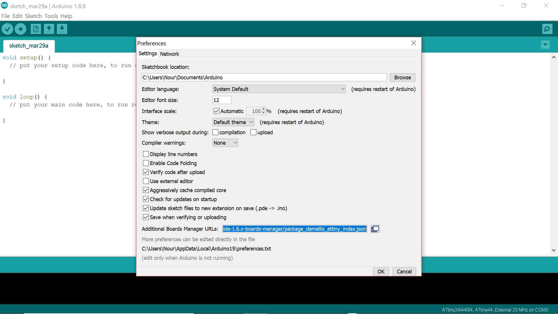
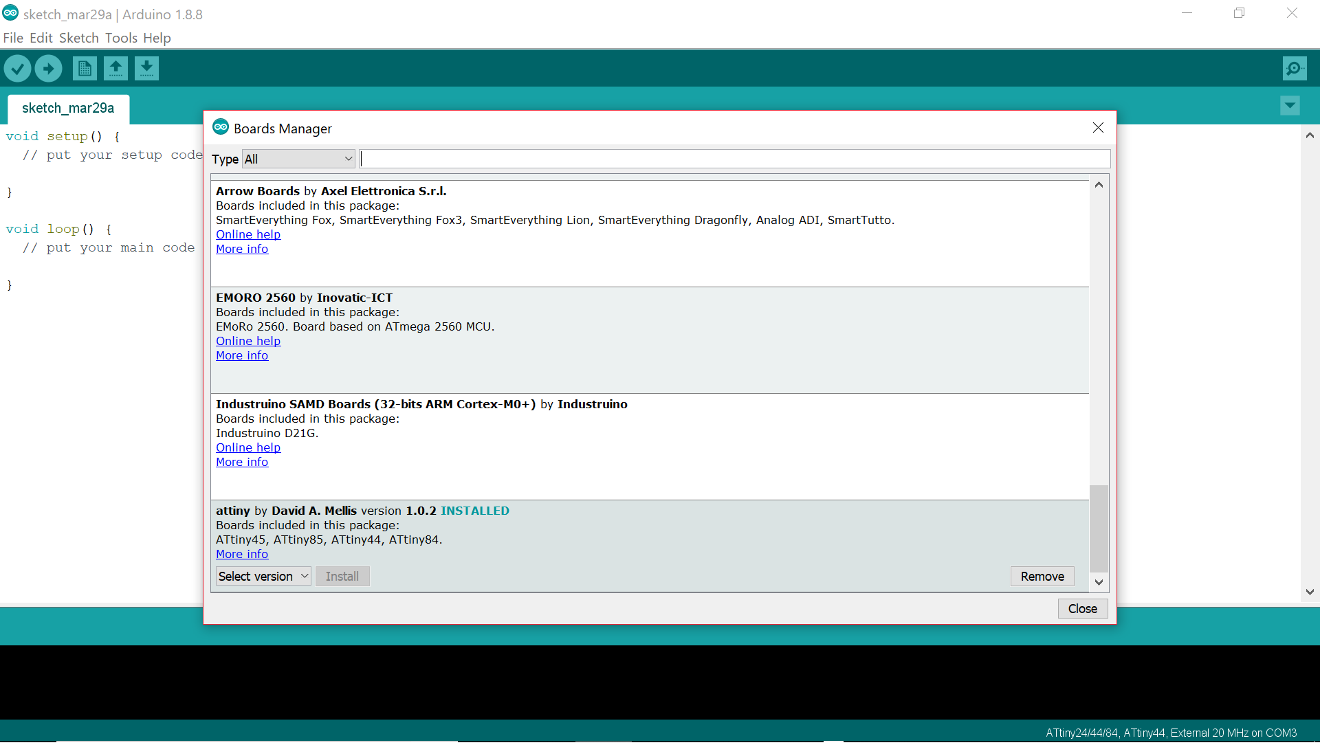
The microcontroller on the Hello Board is the ATTINY 44 so we need to make it clear for the ARDUINO that it is dealing with this MCU. And for doing so, we need to install the ATTINY 44 by going to FILE>PREFERENCES and inserting the following link: "https://raw.githubusercontent.com/damellis/attiny/ide-1.6.x-boards-manager/package_damellis_attiny_index.json" in the Additional Boards Manager URLs
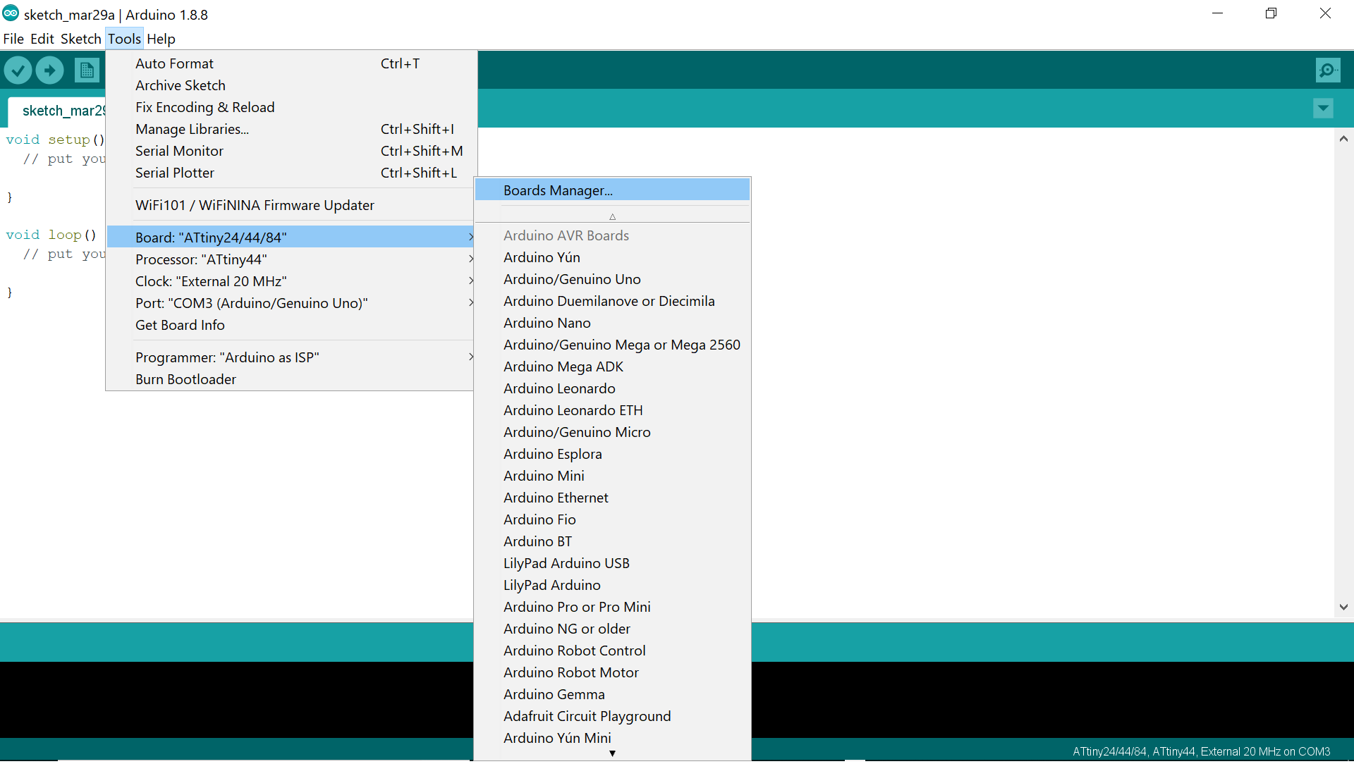
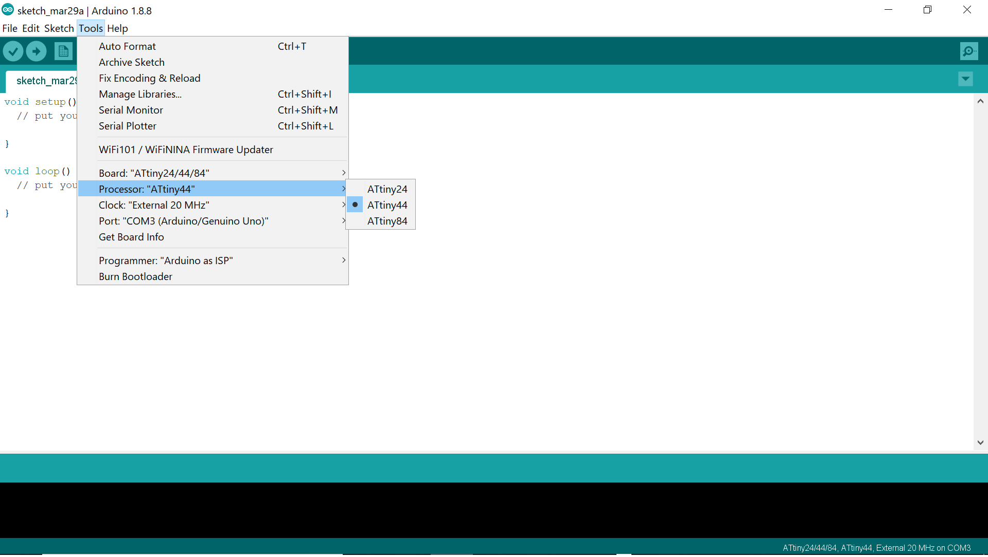
Then go to TOOLS> Boards Manager and install the attiny44 then choose processor as Attiny44 and select clock
Then select programmer as ArduinoISP, burn Bootloader, and finally upload my sketch
In order to write down my sketch, I need to know the below connections that explain how the ATTINY44 can be connected to an ARDUINO
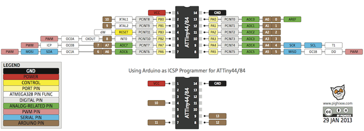
Following the above, we can note the following:
And here is the sketch that I have used in which I wanted the red button to light up the red LED when pressed for 1 second and the blue button to light up the blue LED when pressed for 1 second
  // constants won't change. Used here to set a pin number:
                        const int button1Pin = 3;//the number of the pushbutton pin
                        const int button2Pin = 2;//the number of the pushbutton pin
                        const int ledPingreen = 7;// the number of the greenLED pin
                        const int ledPinred = 8;// the number of the redLED pin

                        // Variables will change:
                        int ledState = LOW; // ledState used to set the LED

                        int button1State = 0;
                        int button2State = 0;
                        int sensorValue = 0; // variable to store the value coming from the sensor


                        void setup()
                        {
                        // put your setup code here, to run once:
                        // set the digital pin as output:
                        pinMode(ledPingreen, OUTPUT);
                        pinMode(ledPinred, OUTPUT);

                        // set the digital pin as input:
                        pinMode(button1Pin, INPUT);
                        pinMode(button2Pin, INPUT);

                        }

                        void loop()
                        {
                        // read the state of the pushbutton value:
                        button1State = digitalRead(button1Pin);
                        button2State = digitalRead(button2Pin);

                        // check if the pushbutton is pressed. If it is, the buttonState is HIGH:
                        if (button1State == LOW)
                        {
                        // put your main code here, to run repeatedly:
                        digitalWrite(ledPingreen, HIGH); // turn the LED on (HIGH is the voltage level)
                        digitalWrite(ledPinred, LOW); // turn the LED on (HIGH is the voltage level)
                        delay(1000);
                        }
                        else
                        {
                        digitalWrite(ledPingreen, LOW); // turn the LED off by making the voltage LOW
                        digitalWrite(ledPinred, LOW); // turn the LED off by making the voltage LOW
                        }
                        // wait for a second
                        // check if the pushbutton is pressed. If it is, the buttonState is HIGH:

                        if (button2State == LOW)
                        {
                        // put your main code here, to run repeatedly:
                        digitalWrite(ledPingreen, LOW); // turn the LED on (HIGH is the voltage level)
                        digitalWrite(ledPinred, HIGH); // turn the LED on (HIGH is the voltage level)
                        delay(1000);
                        }
                        else
                        {
                        digitalWrite(ledPingreen, LOW); // turn the LED off by making the voltage LOW
                        digitalWrite(ledPinred, LOW); // turn the LED off by making the voltage LOW
                        }

                        }
And you may finally check out the test working in the video below!!