6/3/2019
Test runout, alignment, speeds, feeds, and toolpaths for your machine
Make (design+mill+assemble) something big
In order to complete this assignment for our Shopbot 96-60-8 (working bed of 2.44m x 1.52m x 0.15m), we have done several tests. But before the tests, we had to know several things:
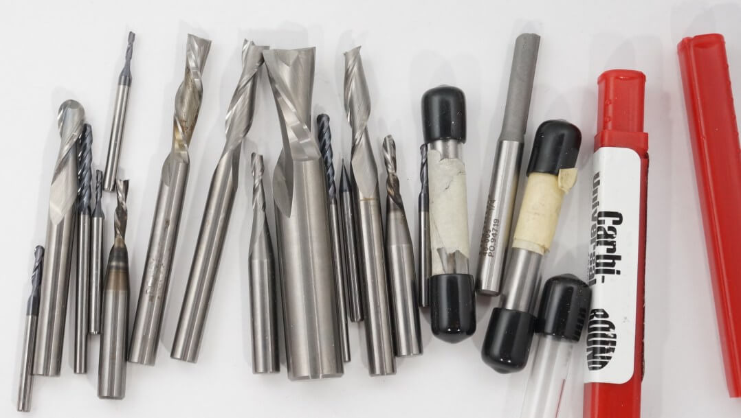
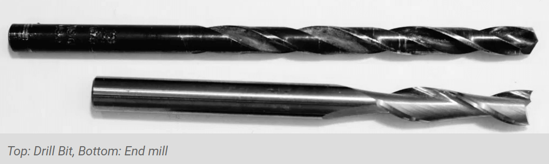
There are two main types of tools used in CNC machining:
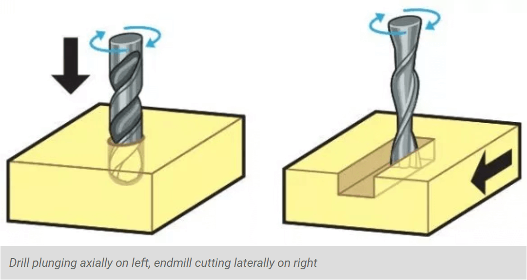
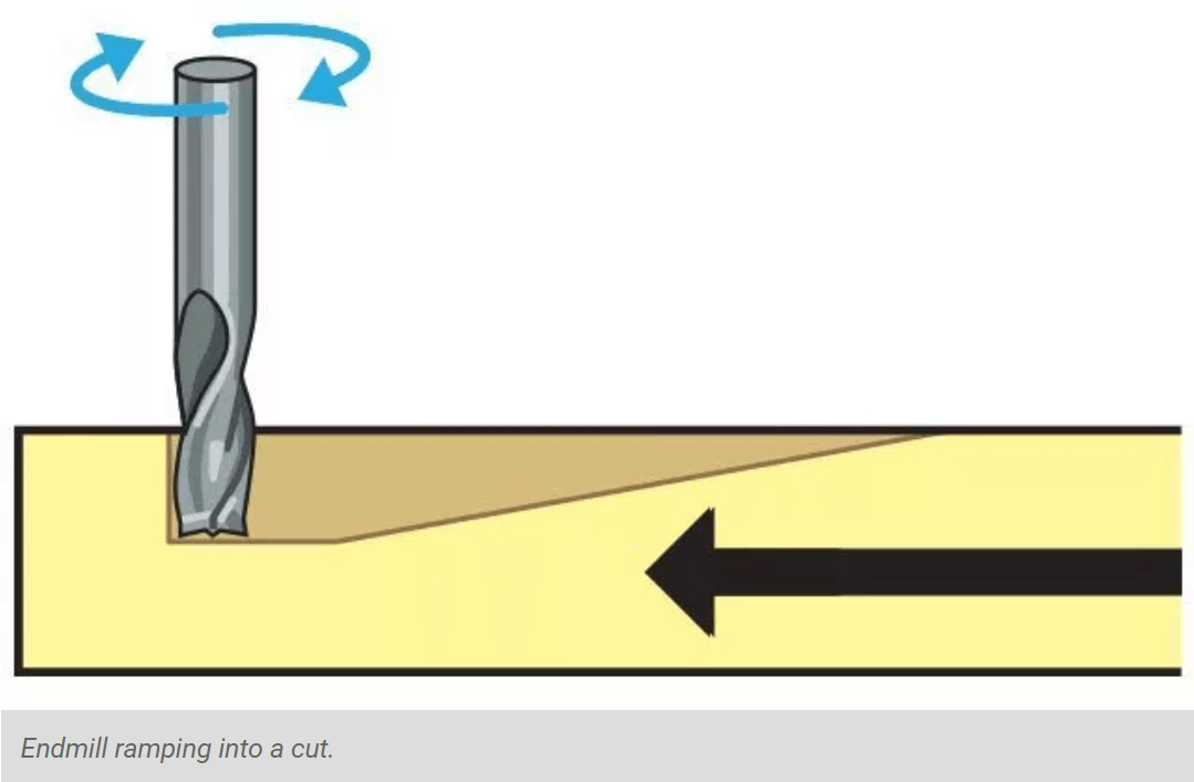
To minimize tool breakage and stress on the material being cut, most CNC software will “ramp” the end mill slowly into lateral cuts
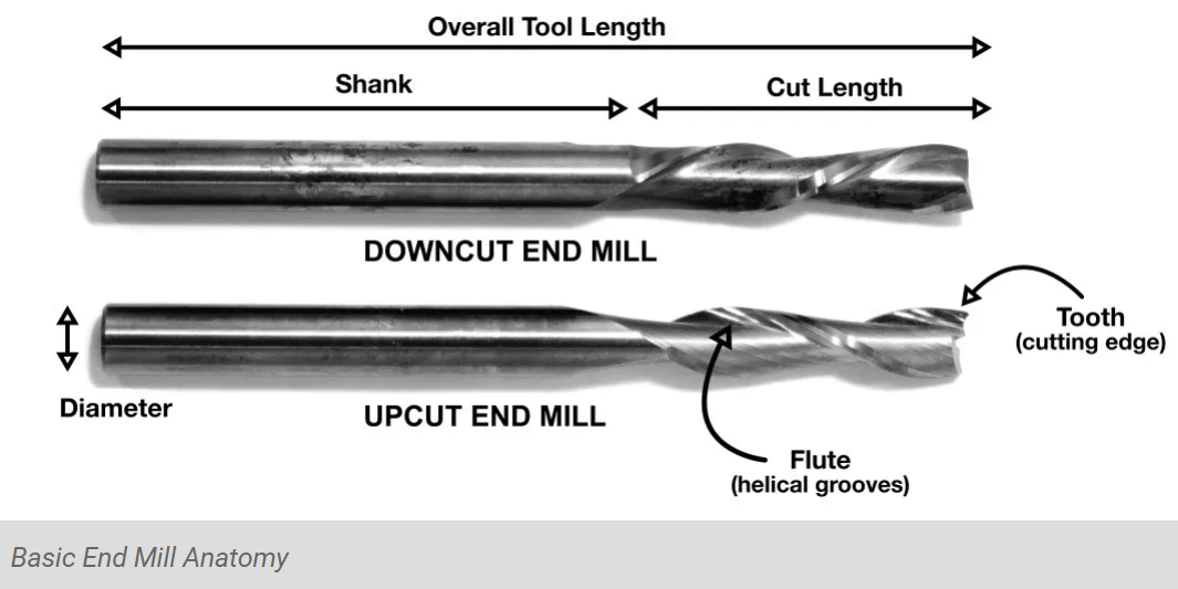
The project type, material being cut, and desired surface finish determines the tool geometry. Key tooling features include the diameter, shank, flutes, teeth, tip shape, center cutting capability, helix angle, helix direction, length of cut, and overall tool length
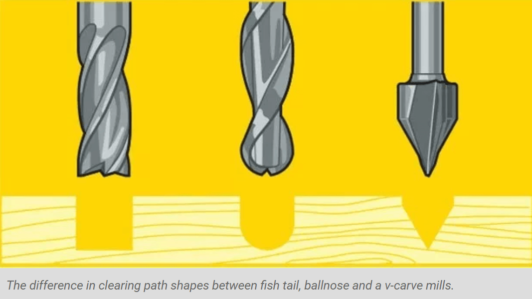
The diagram above shows the difference in clearing path shape between a fish tail, ball nose and V tools. Ball nose mills are often selected when doing 3D contouring because their rounded edge reduces jagged steps when cutting several stepped layers
Flutes are the helical grooves that wrap around the sides of the end mill. Each flute has a single tooth with a sharp cutting edge (although there can be more than one) that runs along the edge of the flute
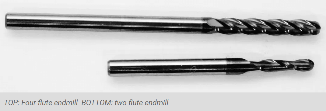
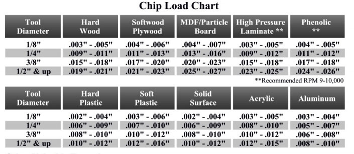
Chipload is the thickness of a machined chip as cut by a specific tool type. More flutes create a smoother surface finish, while fewer flutes remove material faster, but make rougher cuts; they are best at chip clearing, keep heat from building up. Two or four flute cutters are the most common
CHIPLOAD CHART:
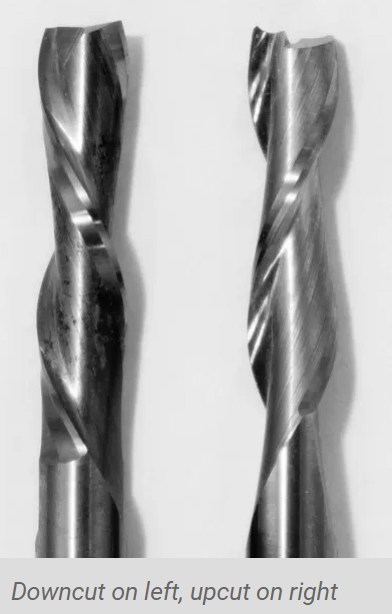
A CNC router spins a cutter clockwise. The helical direction of the flutes as they wrap around the tool determine if chips are ejected towards the top or bottom of the workpiece
upcut mills eject chips towards the top of the workpiece, producing a cleanly cut bottom surface. The downside is possible surface splintering or “tearout” on the top surface as the chips are ejected upwards. Downcut tools do the opposite, producing a smooth upper surface. They are ideal for pieces that have been previously engraved or v-carved and cannot be flipped to hide tearout
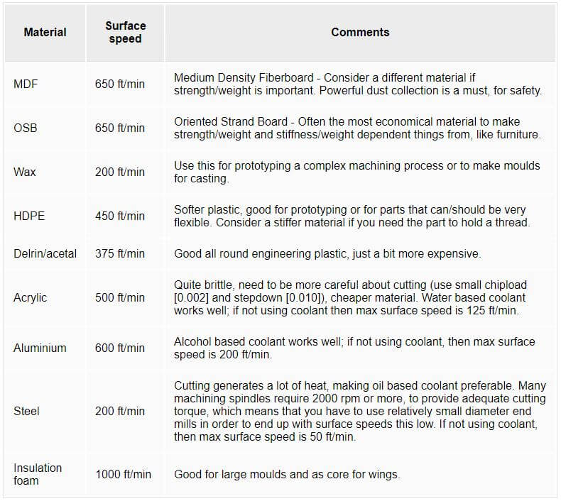
The speed at which we move a cutter across the material is called the “feed rate”. The rate of rotation is called the “speed” and is controlled by how fast the router or spindle turns the cutting tool. Both feed rate and spindle speed will vary based on the material being cut. A general rule of thumb is that you want to move the tool through the material as fast as possible, without sacrificing surface finish. The longer the tool rotates in any one place, the more heat that builds up. Heat is your enemy and can burn your material or radically decrease the life or your cutting tool
SURFACE SPEED FOR SOME MATERIALS:
EQUATIONS:
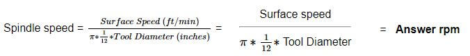
Now that we know the above, we can do the needed calculation for our test
The material we are testing is plywood and which has a similar surface speed to the MDF: 650 ft/min. So the calculation gives us an answer or 10000 RPM. The average of the chipload for the plywood is 0.012 inches and which needs to be divided by two so 0.006 inches (plung rate 50%). That gives us a feed rate of 120inches/min. Note that the milling bit we are using is 1/4'' or 6mm with 2 flutes
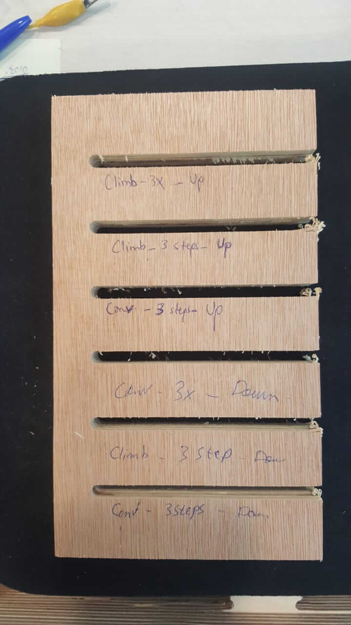
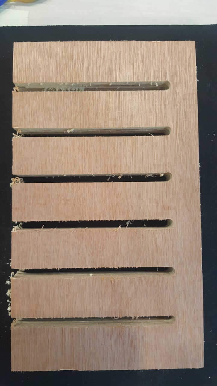
They perfectly fit
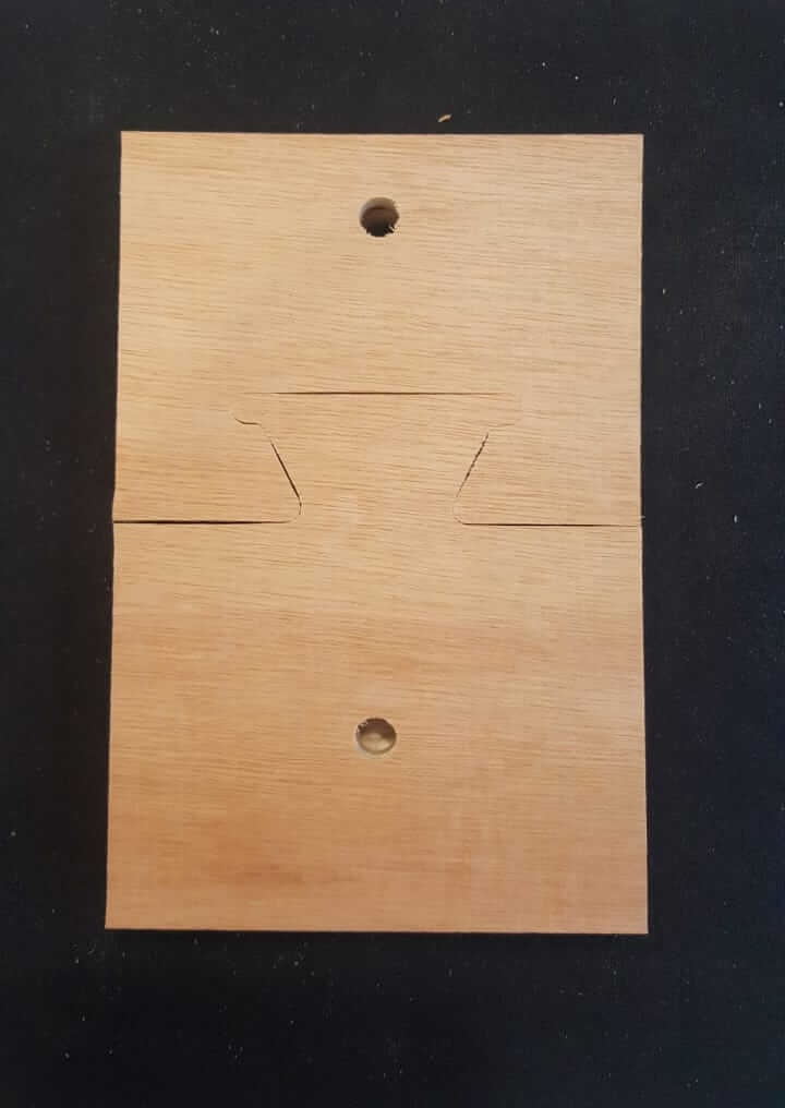
They perfectly fit
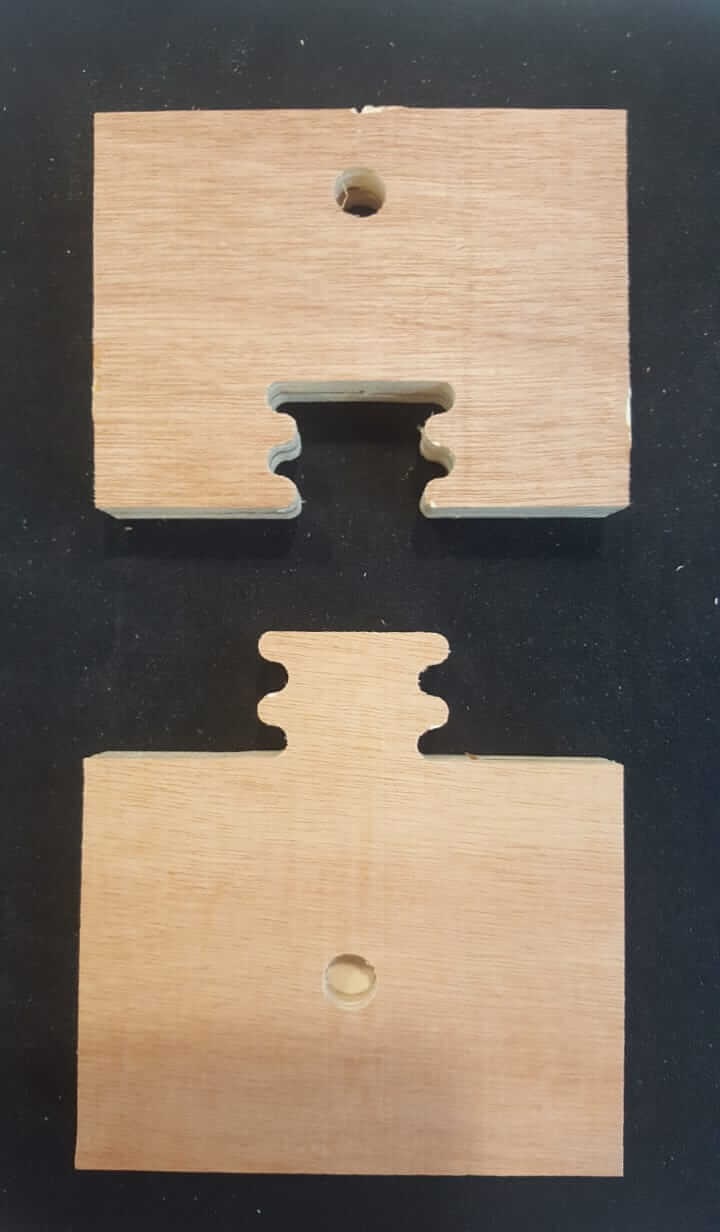
They do not fit
They are quite loose
17.2 mm happens to be the best fit
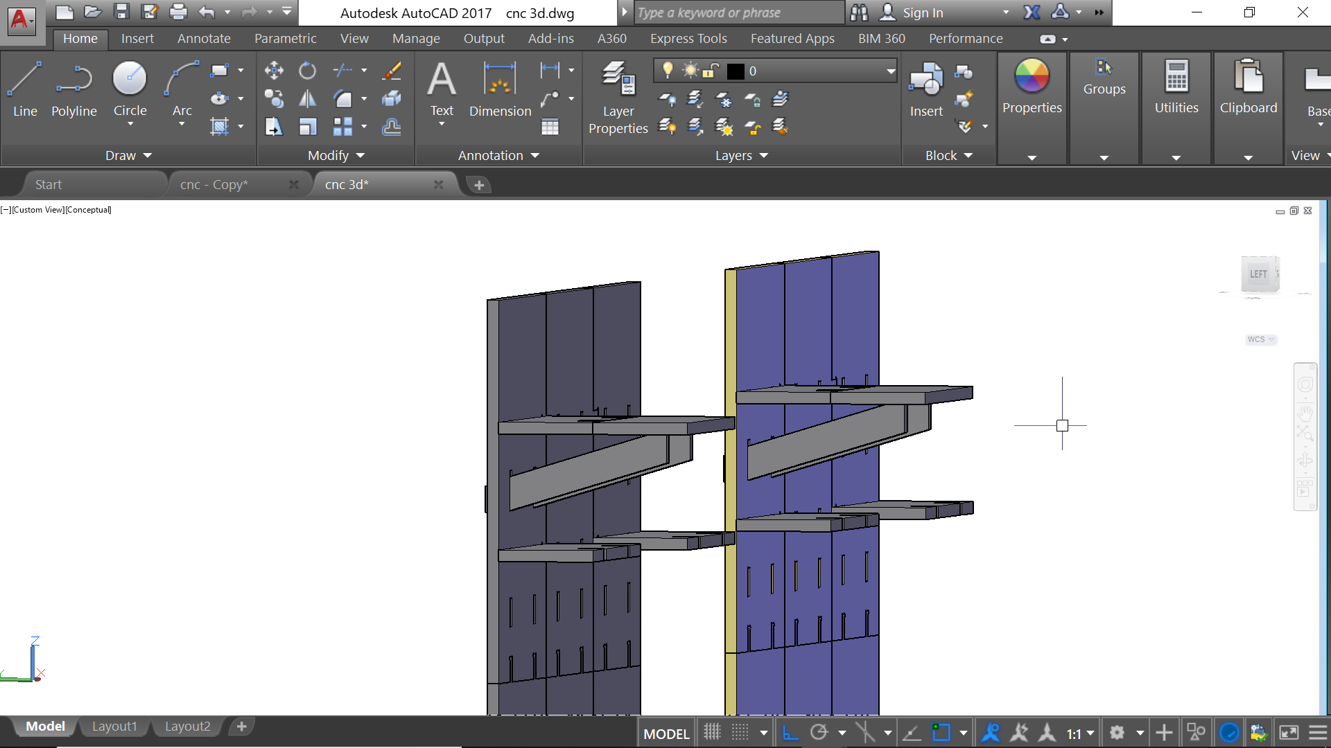
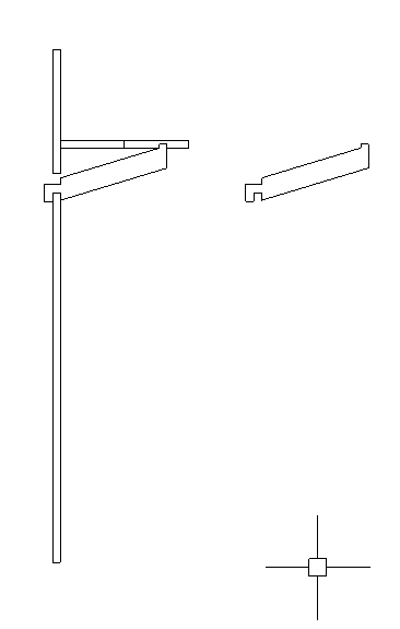
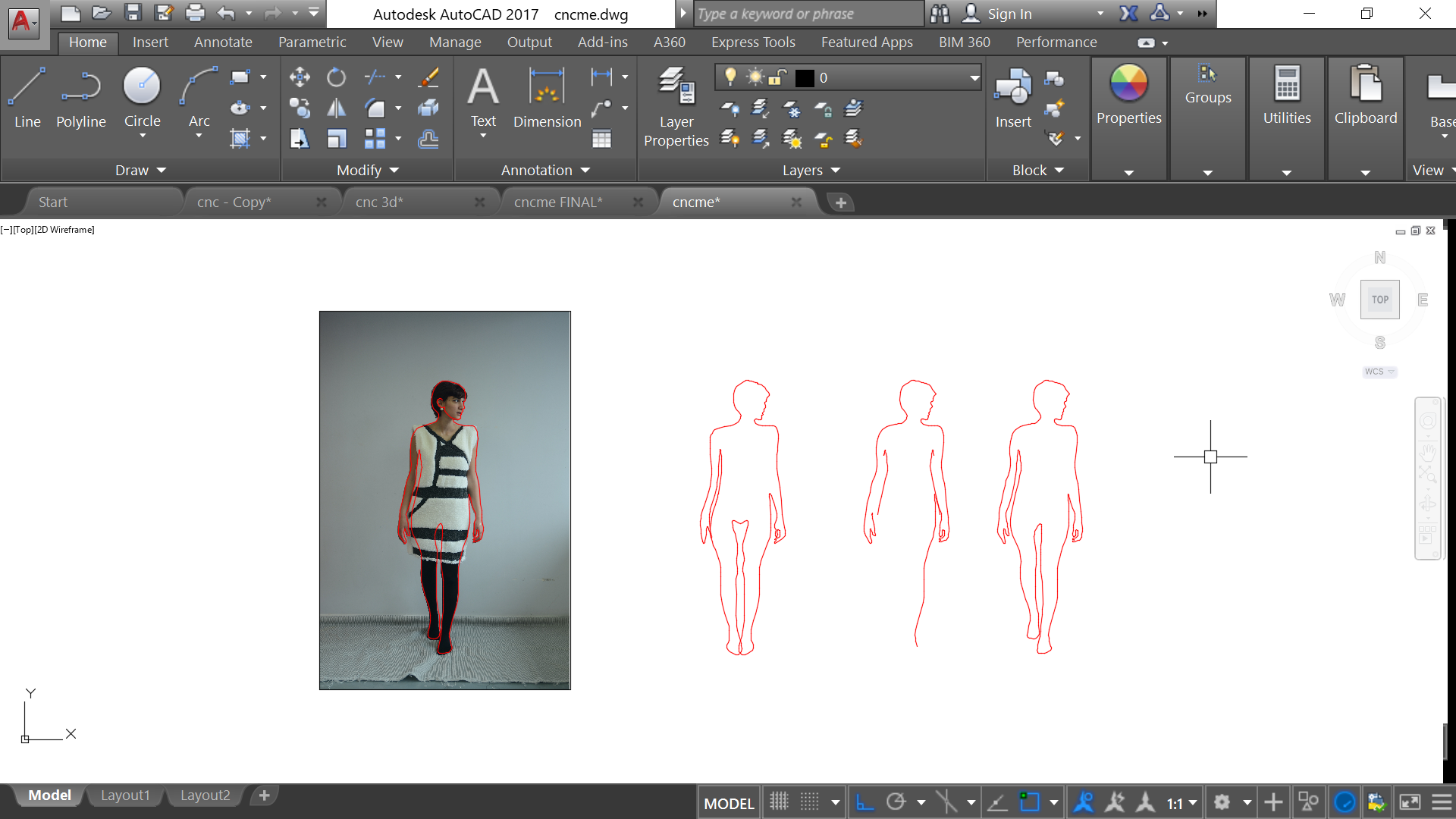
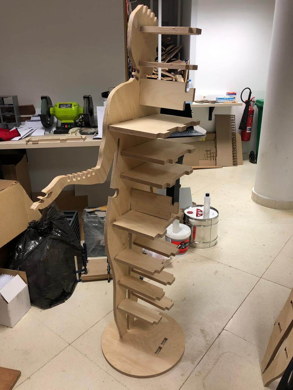
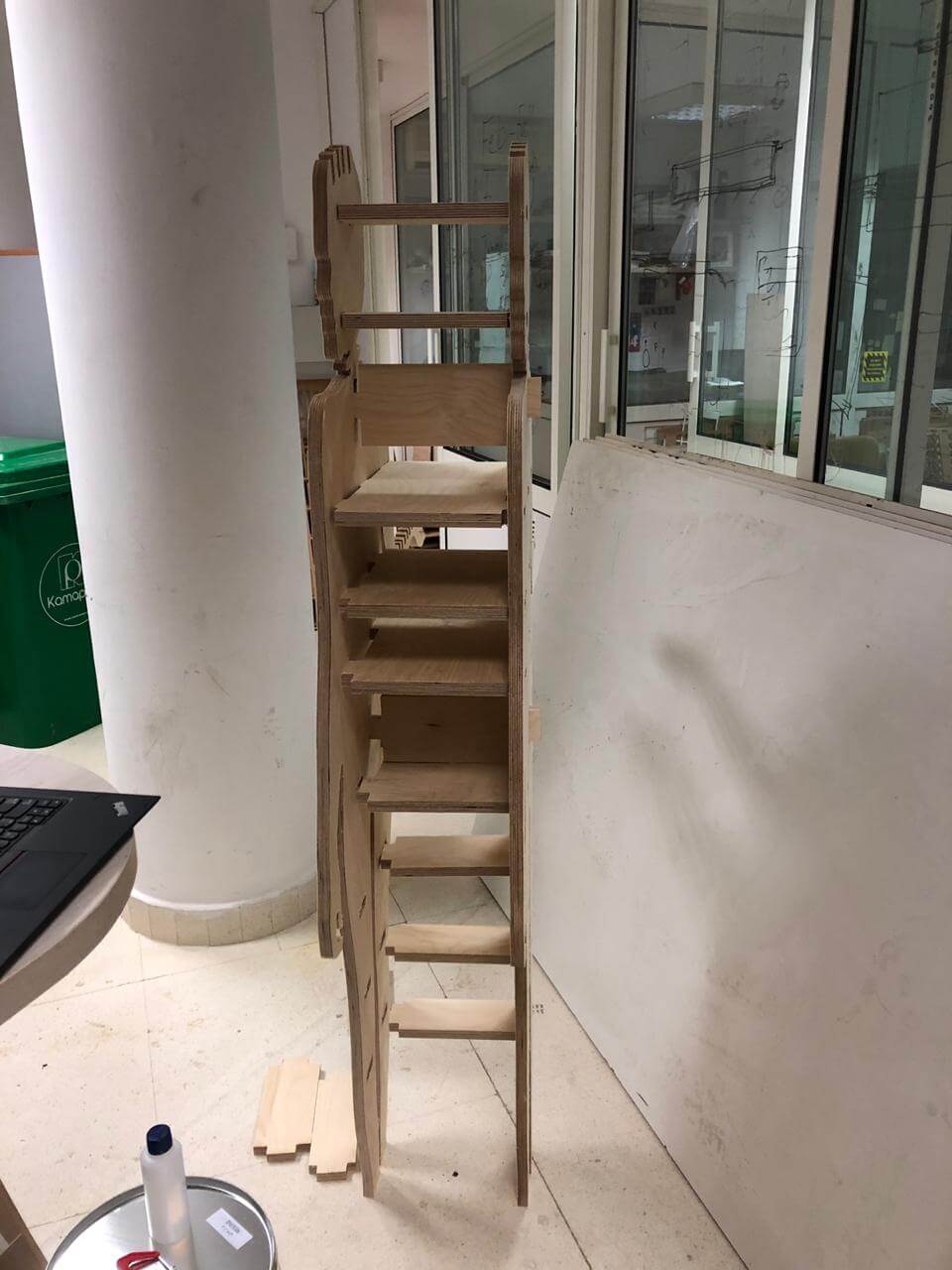
For this assignment, I used AutoCad for drawing my design. I wanted first to make some shleves that I can use in my workshop at home; But then I changed my mind. However, I am documenting the first idea of the shelves and want to highlight the fact the the cantilever that is supporting the shelves happened to be weak. I could have modified the design so they can be stronger but I preferred to CNC my silhouette in order to have it as a prephase for my final project. Let's take a look at the first shelves' design...
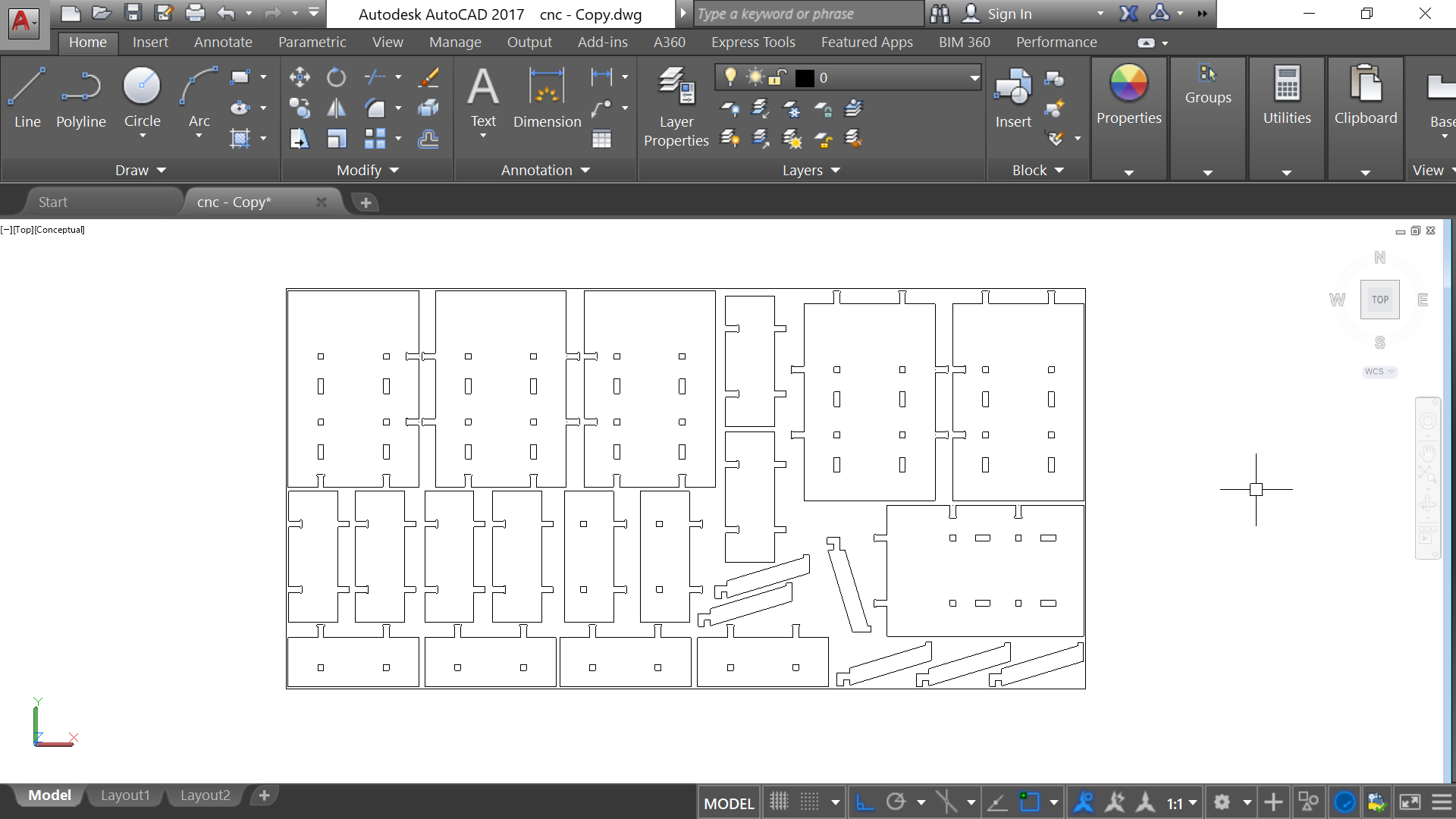
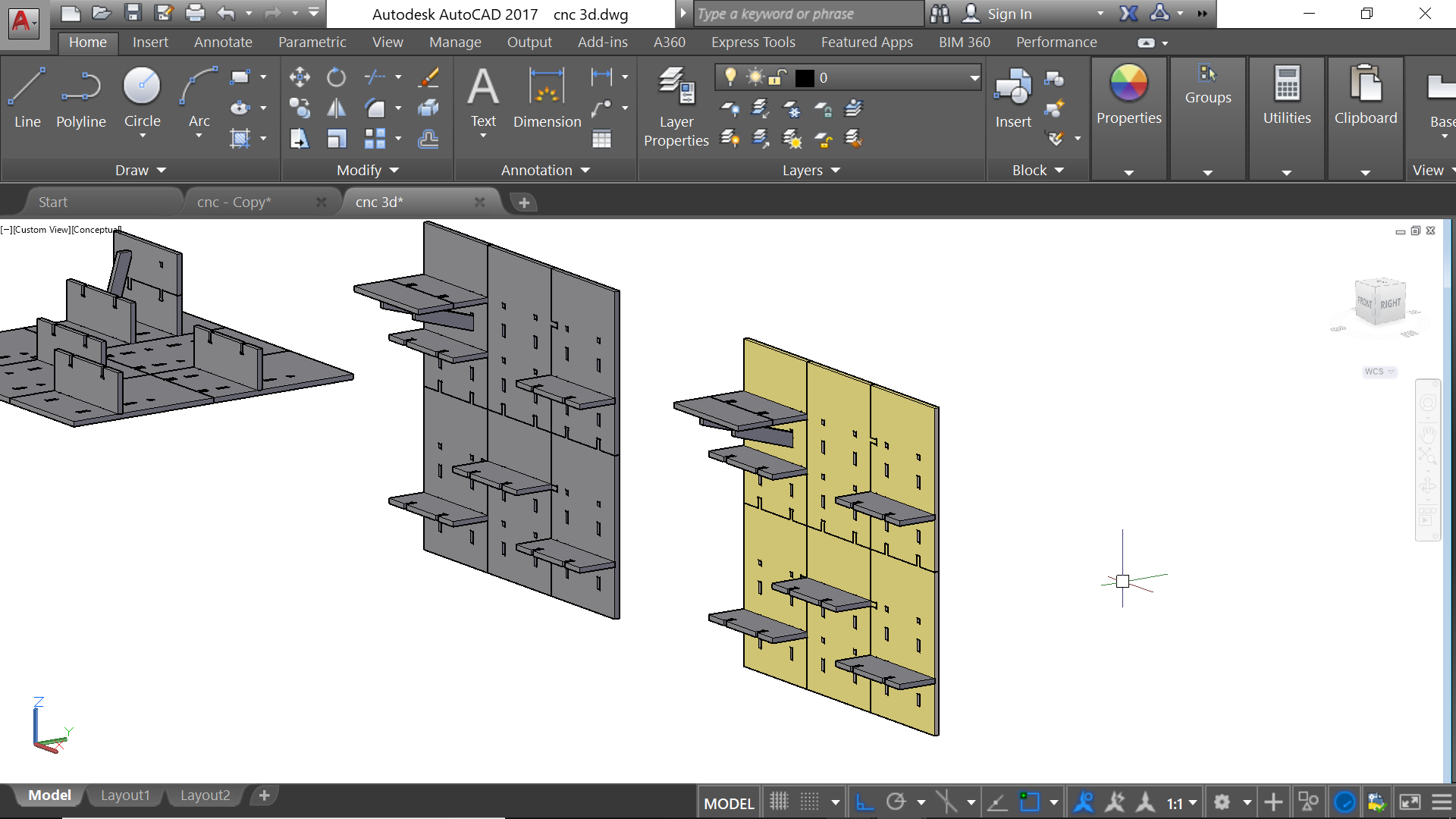
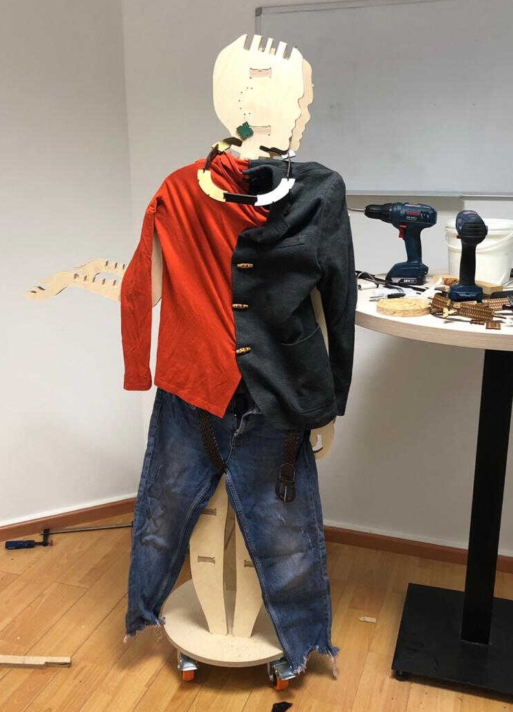
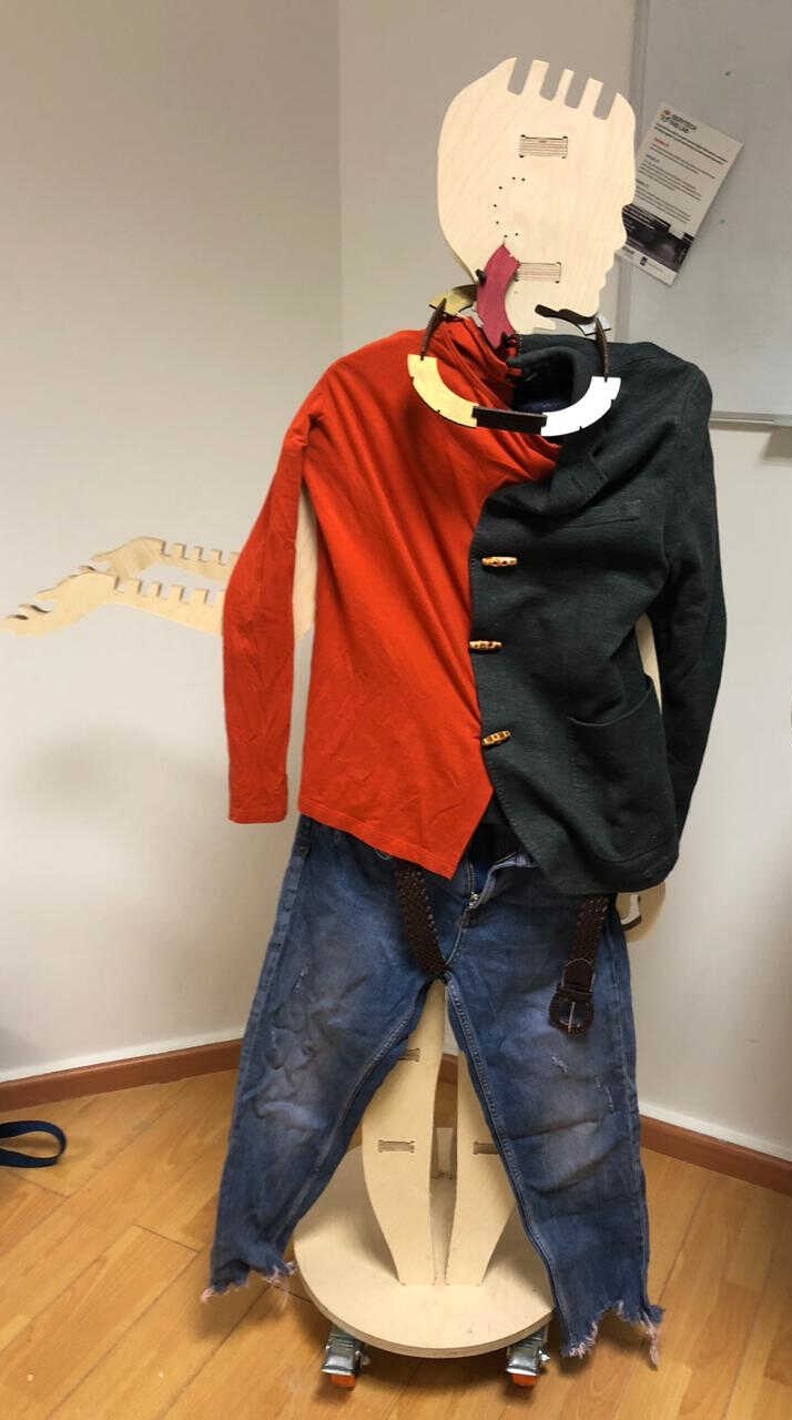
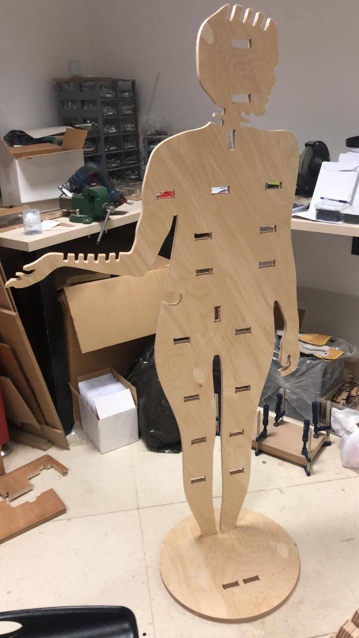
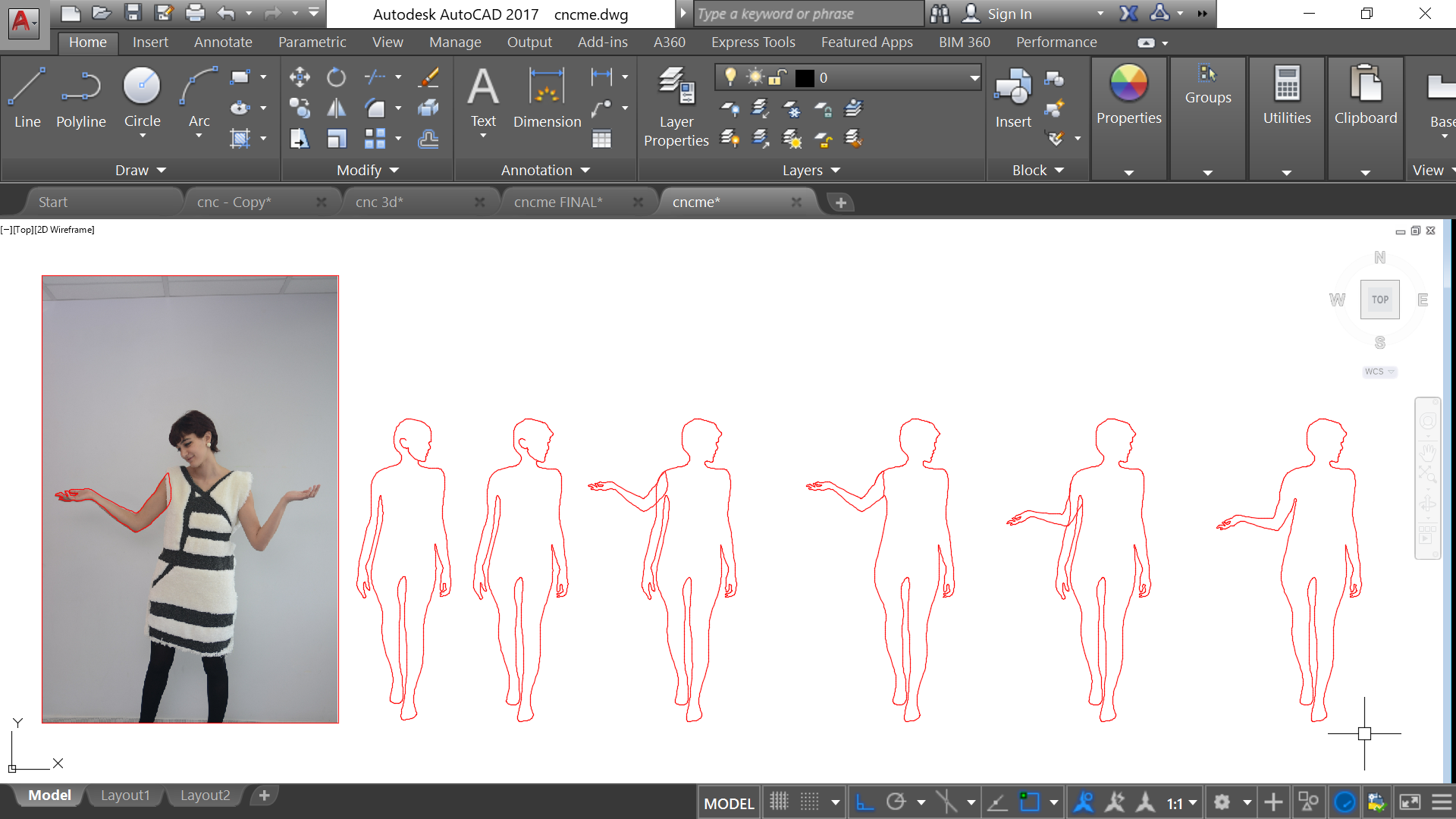
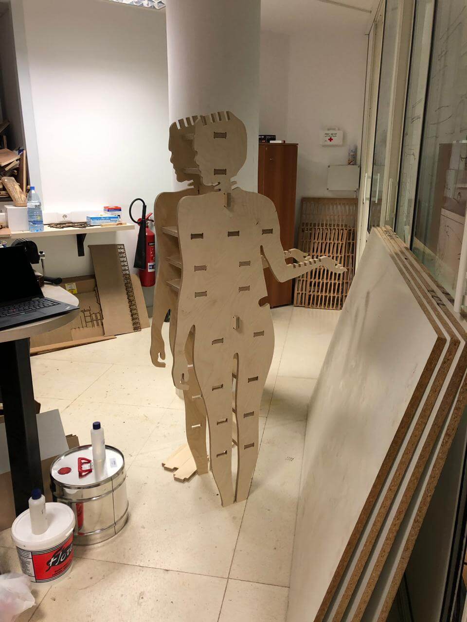
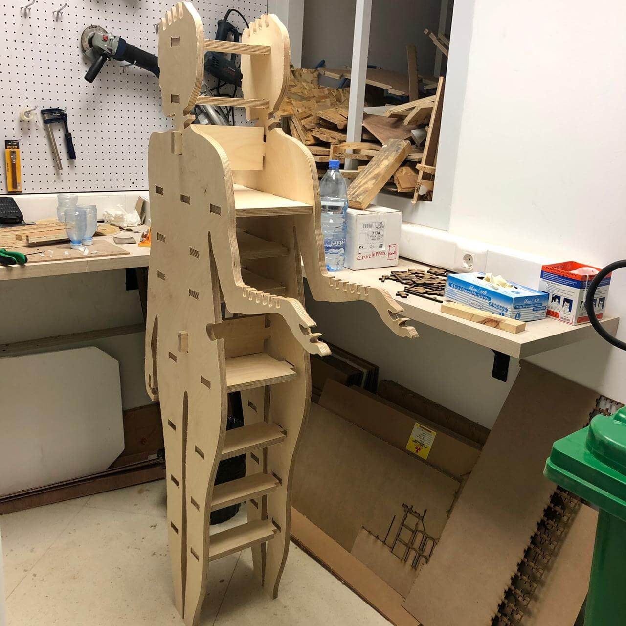
Then I have moved to the other idea, where I wanted to see my full silhouette being able to hold some items of clothing and acting as a storage with small shelves sandwiched in between my figures. This was way more fun than the previous one and as I have previously mentioned, it is a prototype for my final project...
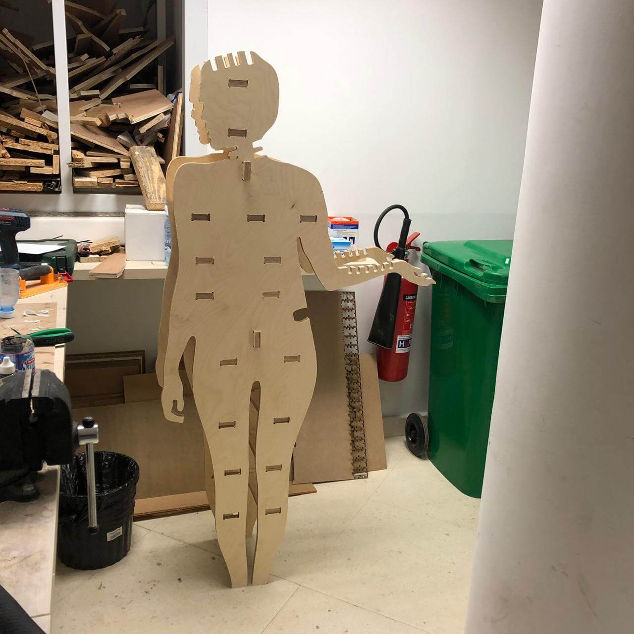
I have first started to trace my silhouette on AutoCad based on 2 images with 2 different gestures. I needed one of my hands to be lifted up soo it can hold some bags later on...
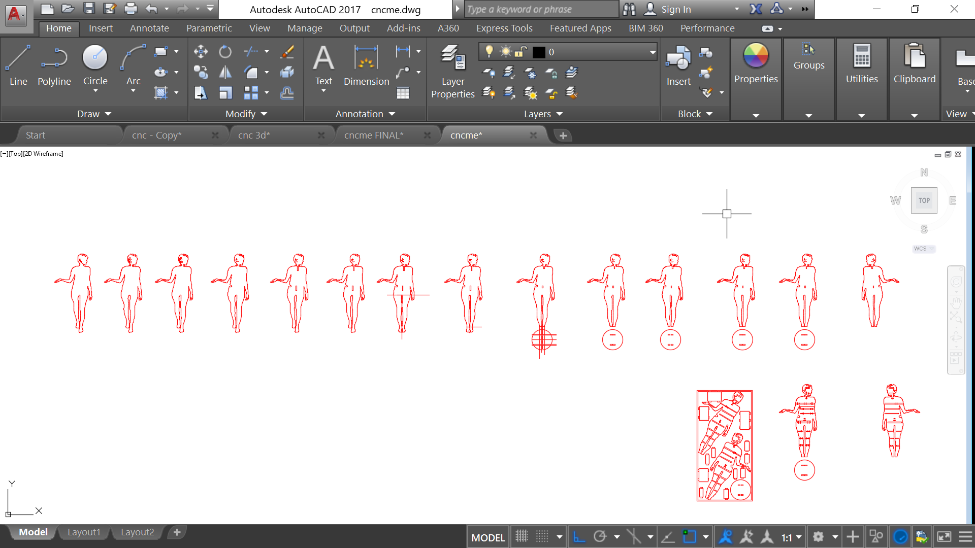
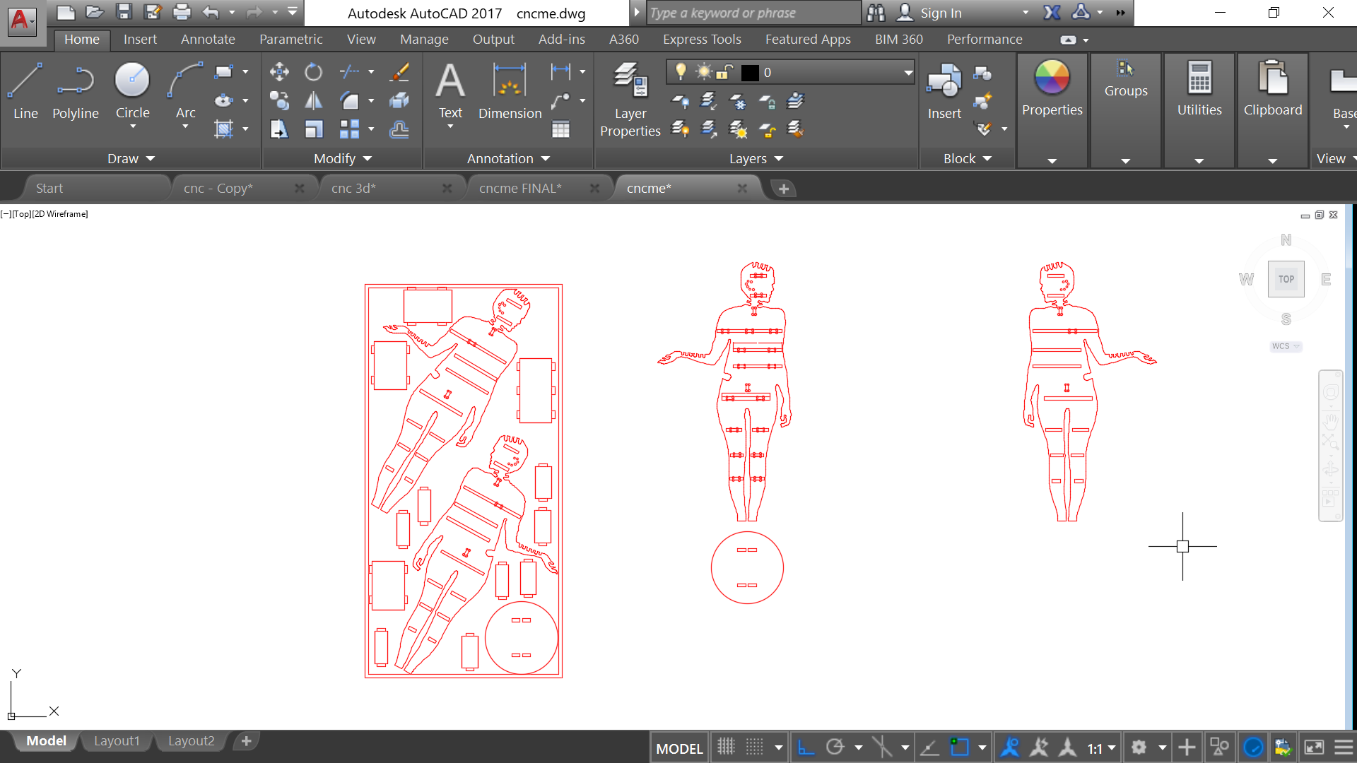
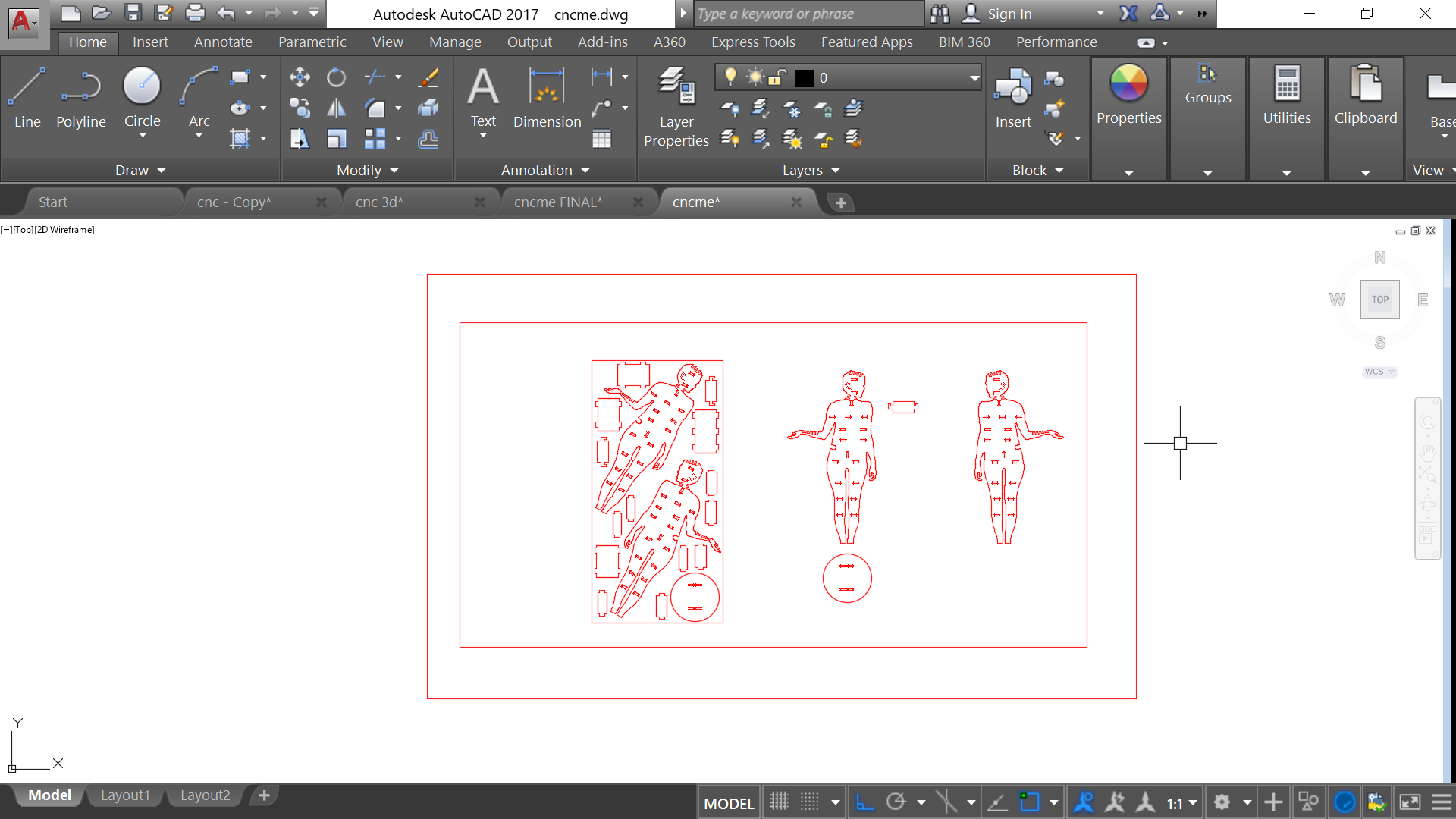
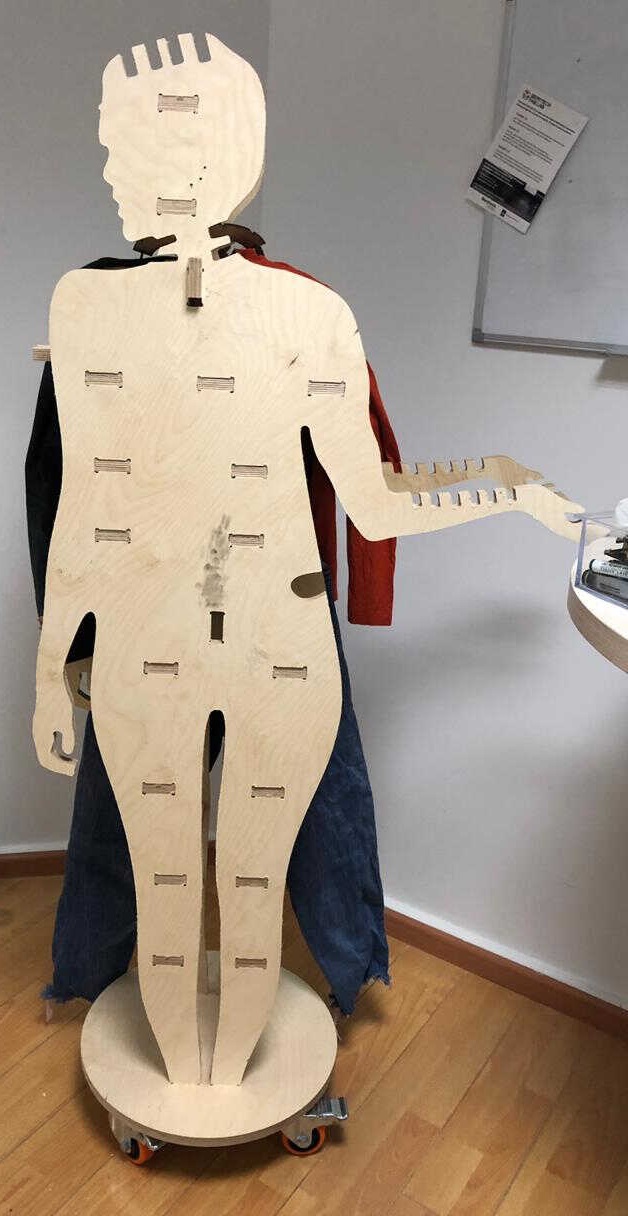
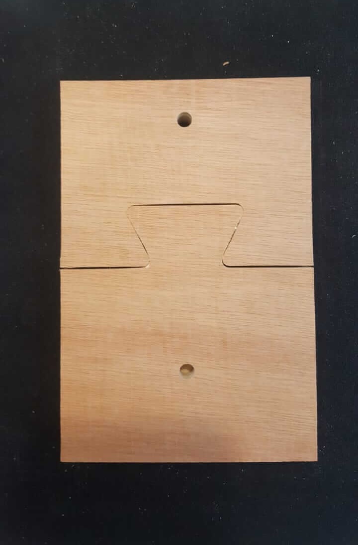
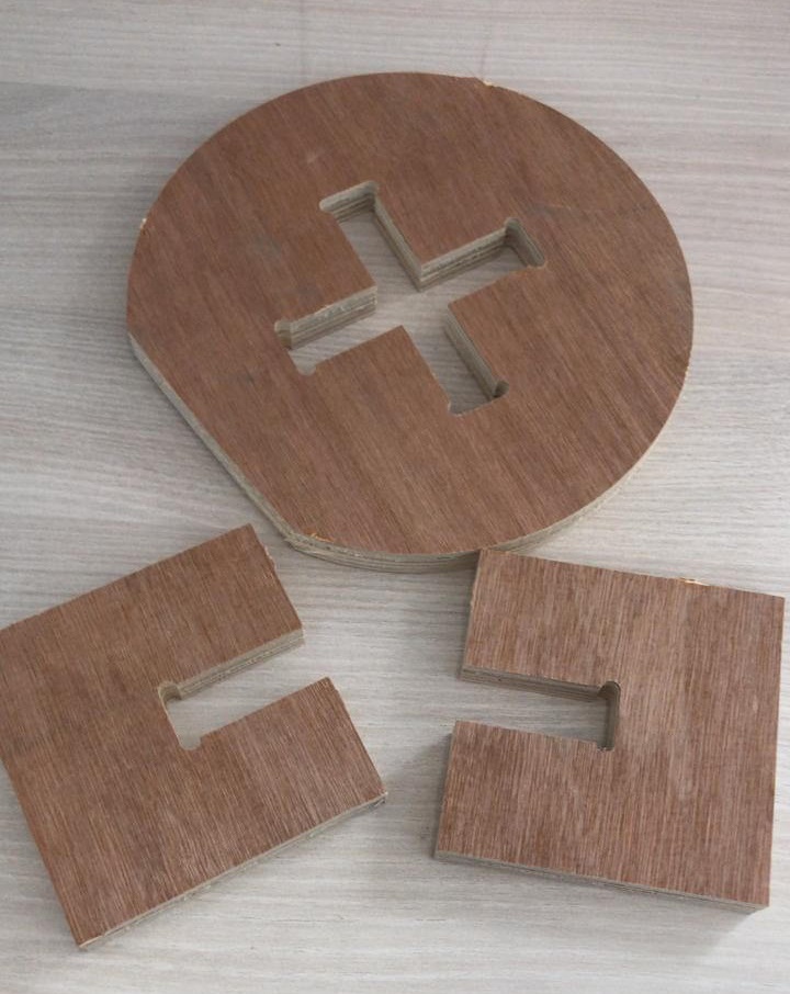
The most important thing is to make sure to join all lines so that you have one full vector for each shape! And to add the T bones where needed while using 17.2mm as a width of the slots in order to have a perfect fit!
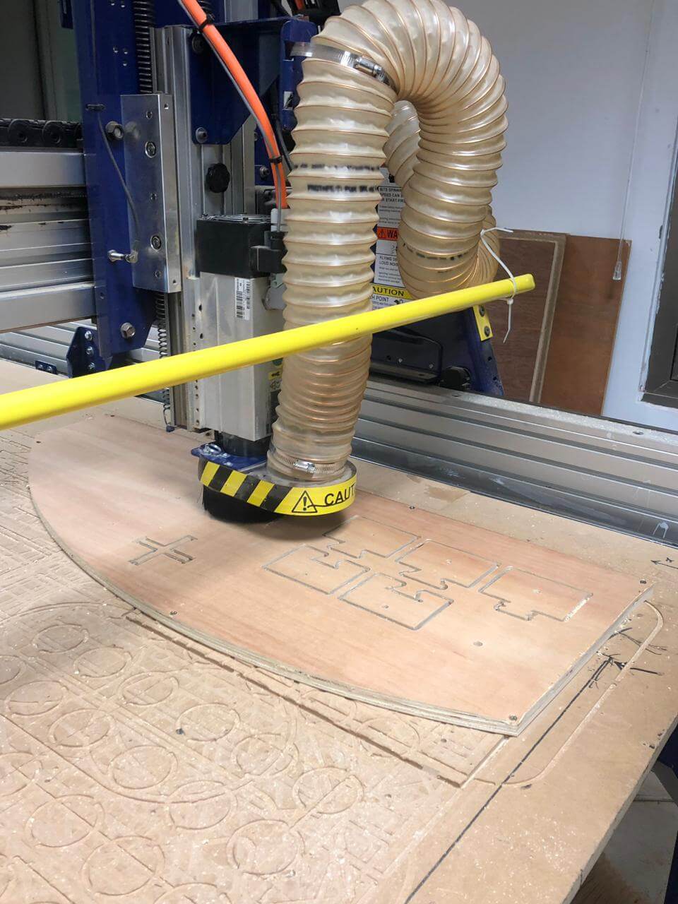
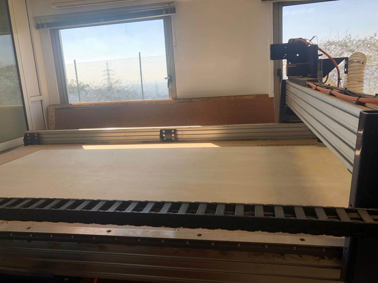
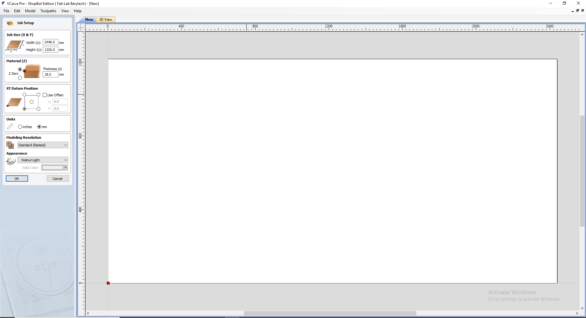
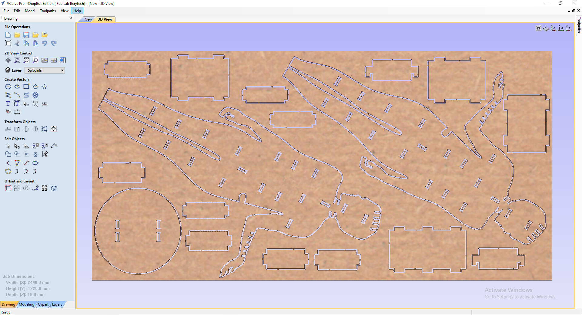
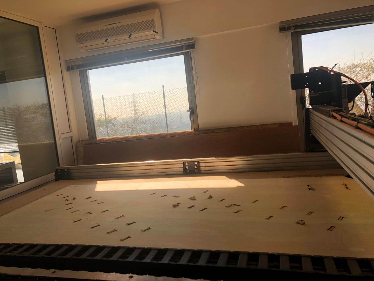
We now move to the CNC room and place the plywood board and open the file in VCarve software to generate the G codes; one for the internal slots and one for the external outline by adding tabs:
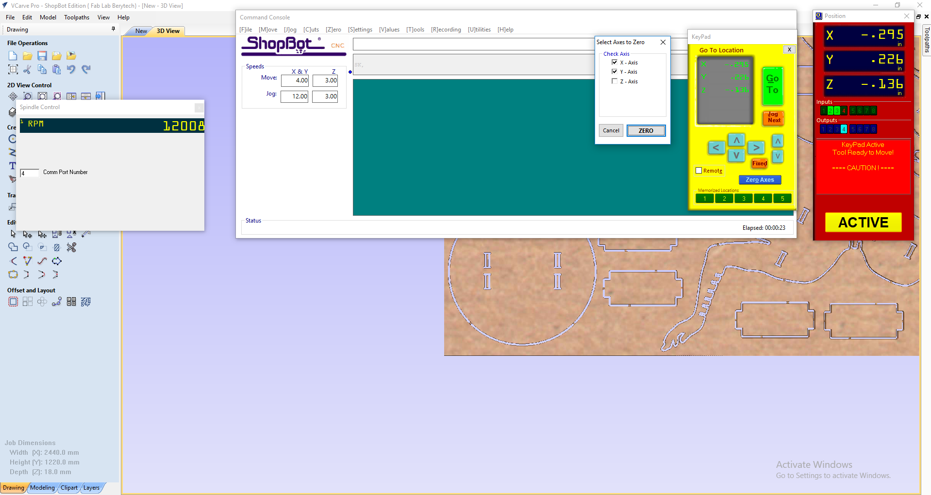
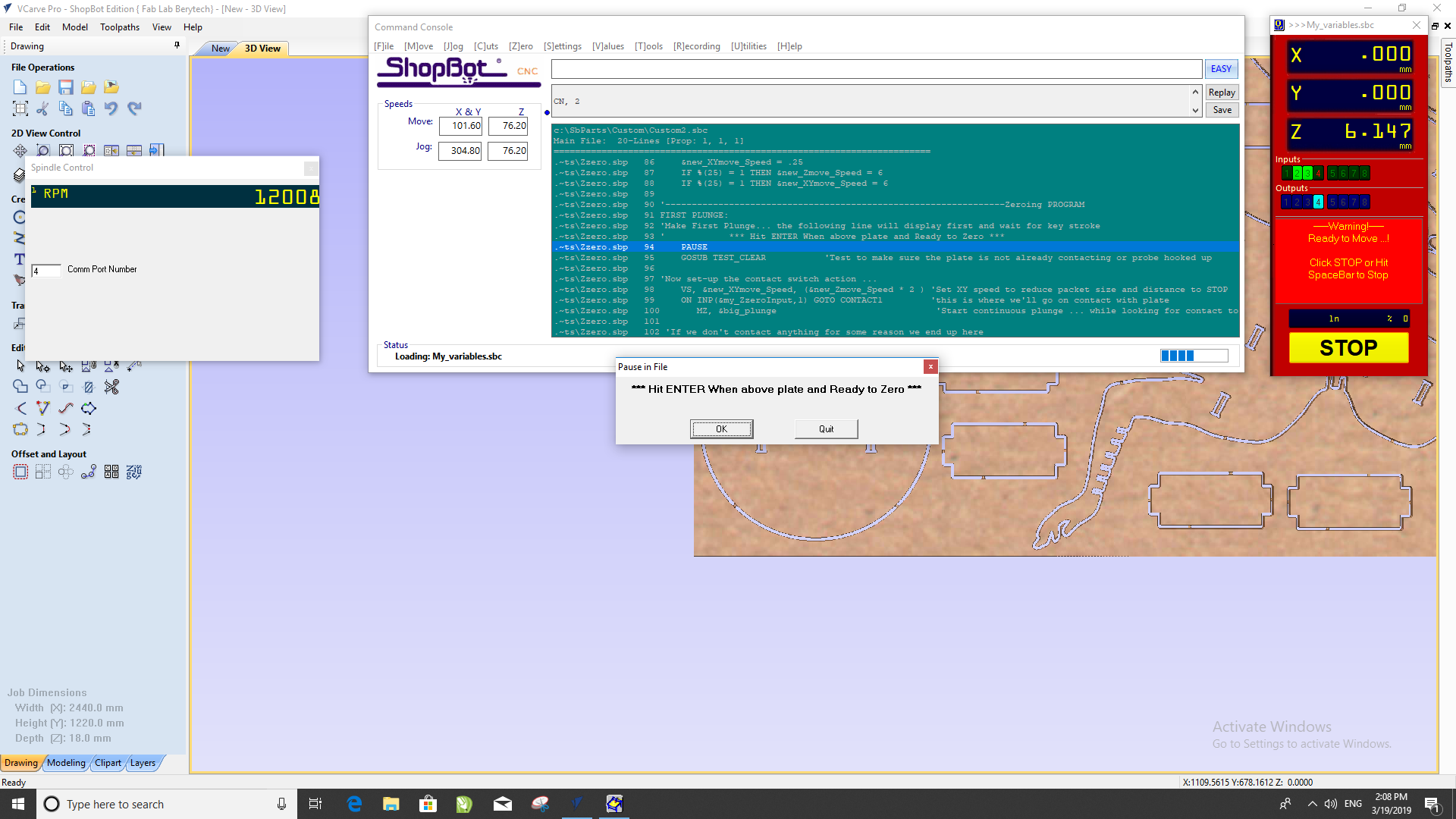
Then place the X and Y and zero the Z axis:
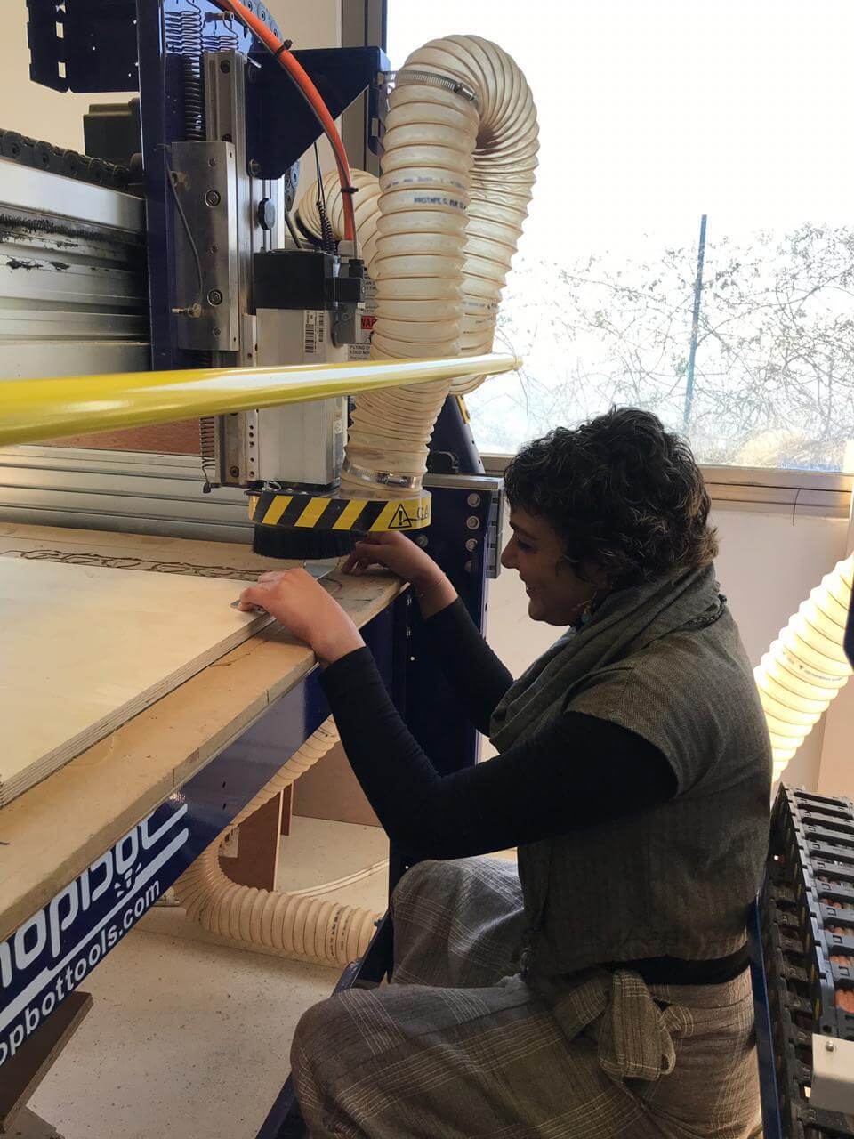
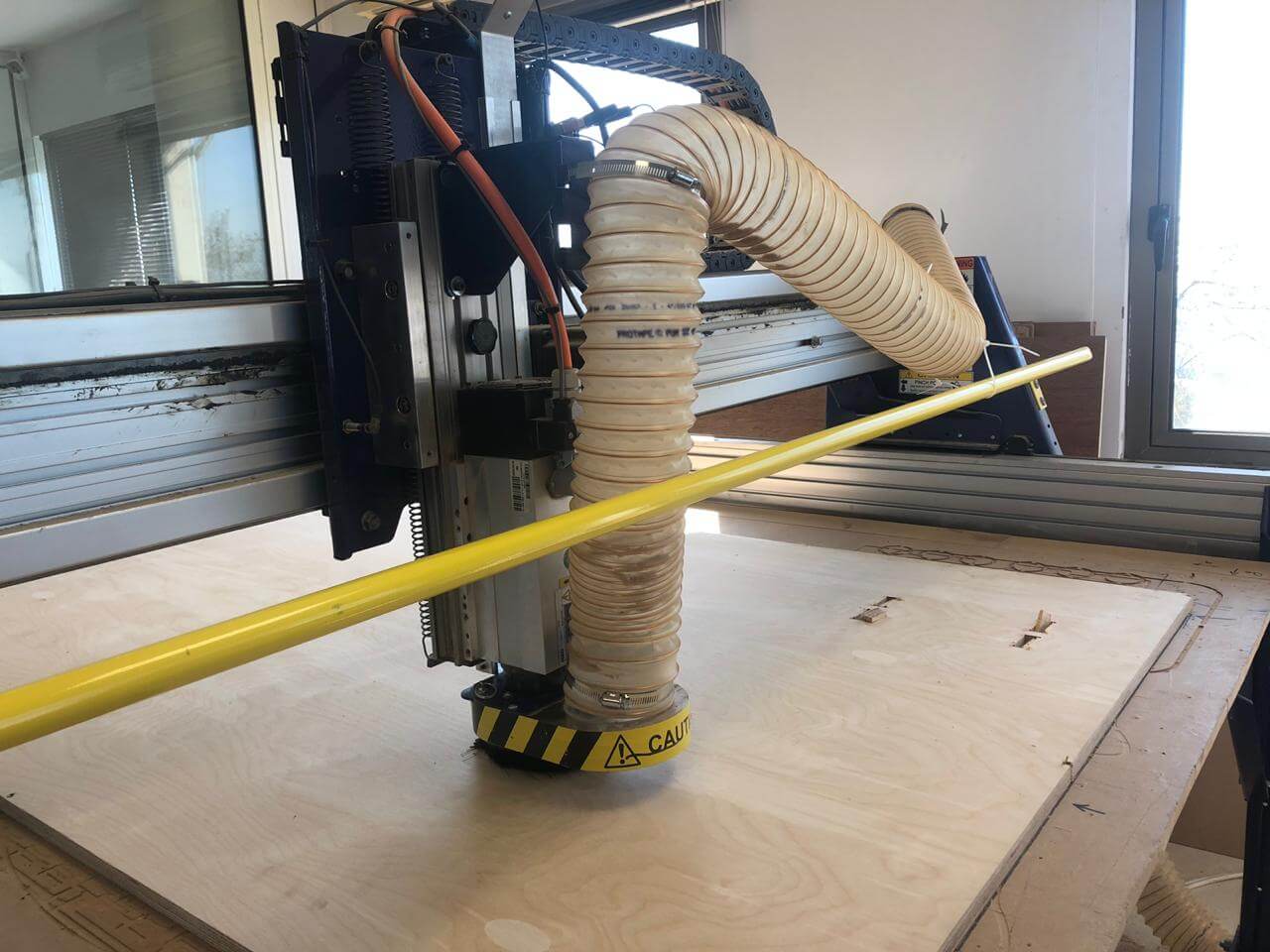
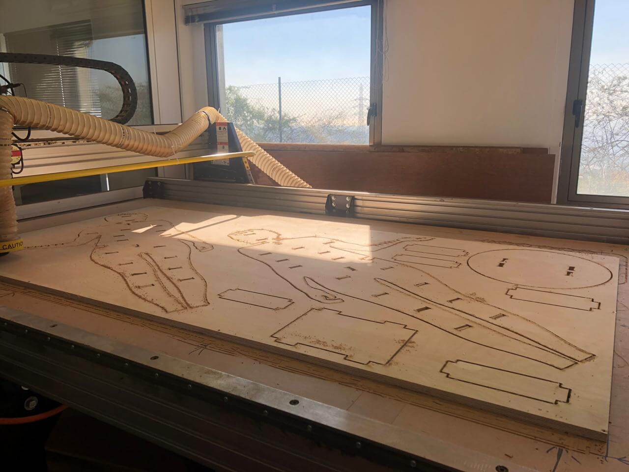
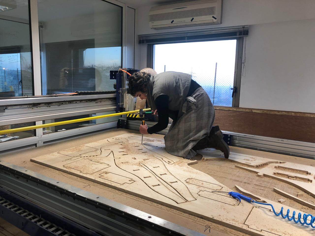
Then start machining while staying quite close and keeping an eye on the CNC:
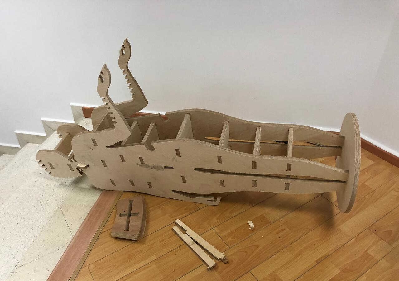
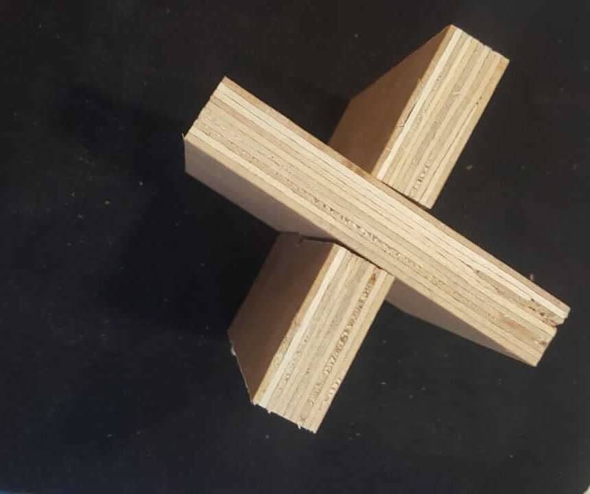
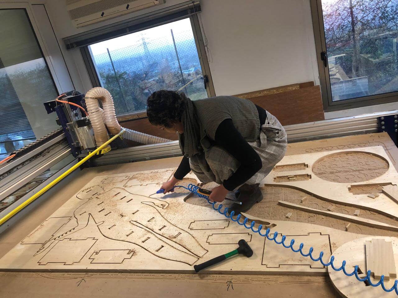
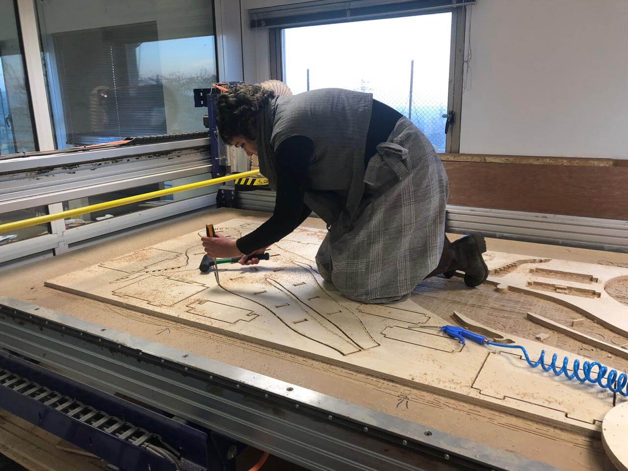
Then it's time to remove the pieces and the tabs with a chisel and a mallet and start assembling...
And the final result is...
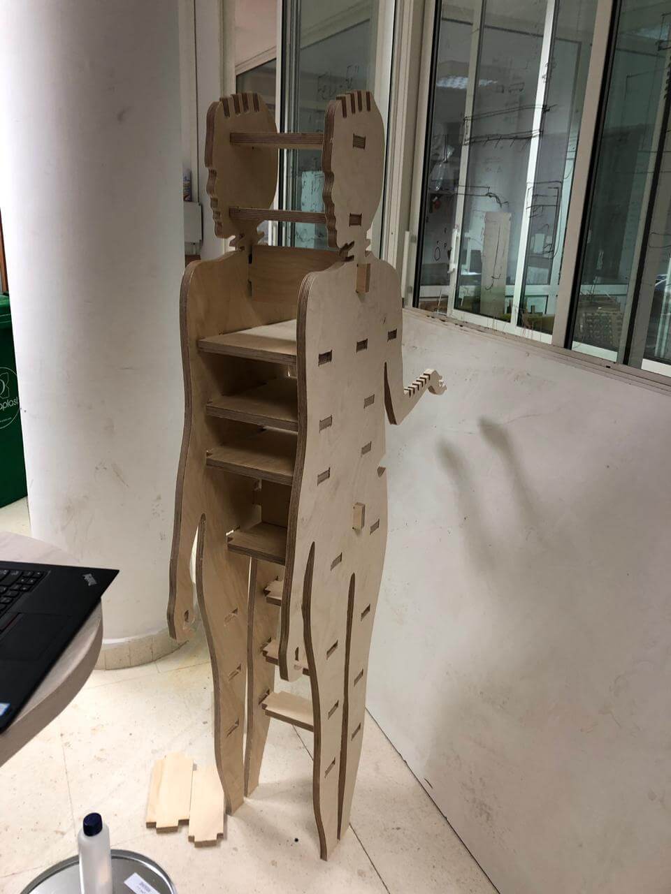
I admit that it was hard to assemble it especially that I have realized that I forgot to add T bones for the tongues; I have just added them for the grooves. That's why I had to put a lot of effort in hammering the pieces in order to fit together and have a 90 degrees angle. I have then decided to assemble it horizontally and removed the vertical lock piece in the middle. And then I added the base and 4 wheels and here it is...