Let's Go...
BUT Before Starting to get to milling process and designing let's know a bit about what is CNC and machining process.
What is CNC Milling?
CNC milling is a specific form of computer numerical controlled (CNC) machining. Milling itself is a machining process similar to both drilling and cutting, and able to achieve many of the operations performed by cutting and drilling machines. Like drilling, milling uses a rotating cylindrical cutting tool. However, the cutter in a milling machine is able to move along multiple axes and can create a variety of shapes, slots, and holes. In addition, the work-piece is often moved across the milling tool in different directions, unlike the single axis motion of a drill.
~Source-
http://www.cnc.com/what-is-a-cnc-mill-and-how-does-it-work/
Basicallyy It's a similar process that we did in Electronics production week using SRM-20 it removed the copper parts but in here we wil be performing those actions on the bigger parts.There is a stock , a bed , a tool which can be moved in x,y,x direction and the tool itself is rotating on the spindle tp to chip off the material.
~Source - Self Understanding
The process involves creating a CAD(Computer Aided Design) file of the desired object. Then a specialized CAM (computer-aided Manufacturing) software is required to convert the 3D CAD file into a set of codes which the machines can understand. CNC machining language, called G-code essentially controls all features like feed rate, coordination, location, and speeds. With CNC machining, the computer can control exact positioning and velocity.
There are certain factors/parameters that must be considered while using a CNC:
- Types of tooling used Selecting a tool to use on a CNC machine mainly depends on the type of material being used, the type of work to be done, the quality of finish and the number of components to be run.
- Tool configuration A CNC machine can have many different types of tool configurations. To select a tool you need to know what the tool configurations are for the CNC machine you are working on.For machining some difficult and hard material, we should take tool configuration in consideration.
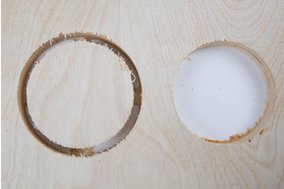
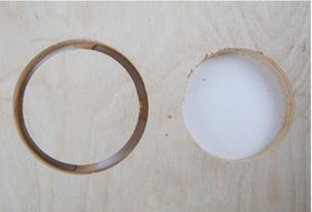
- Direction of cut The direction of cut affects the life of a tool, the quality of the cut and the material you are working with. When selecting a tool it's important to consider the type of material you are using, the needs of the customer and the specifications of the CNC machine being used.
- Cutting speed Cutting speed is the peripheral speed of the tool. Sometimes you may need to calculate cutting speed mathematically. Or, you might use a cutting table. Whichever way you do it, you need to know the cutting speed and RPM for the tool you have selected on the CNC machine you are using. Sometimes cutting speed is confused with feed speed. Just remember that cutting speed is in relation to the tool itself while feed speed is in relation to the movement of the tool.
- Spindle and feed speed Feed speed is the rate at which the workpiece moves into the cutter. It is always determined in relation to the spindle speed. Using the wrong feed speed can produce too much dust or burn the workpiece. To determine the optimum feed speed you can use a feed speed table or calculate it mathematically.
- Understanding Bits CNC routers need bits. They determine the kind of carving you can do, the resolution of your finished designs, and how fast you can move through the material. They come with cutting edges that pull up or push down (sometimes both), they have square or shaped ends, they are made for speed or accuracy, and they come in diameters from a pinpoint to over two inches for standard CNC routing.
Source~ https://www.linkedin.com/pulse/5-factors-should-consider-selecting-cnc-tooling-clara-xiong/Deep dive into Anatomy Of Bits
Milling is done using a cylindrical milling tool mounted in a milling tool holder that is then mounted in the tool spindle on the machine. Mostly the drill bits are made of Carbide Steel or HSS(High Speed Steel).
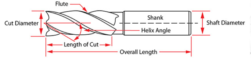
Each of the labelled parameter abaove is responible for its specific type of operation.
Source~
http://www.tinkerandfutz.com/a-guide-to-cnc-bits/
http://www.carbideprocessors.com/pages/technical-info/types-of-drill-bits.html
Difference between Drill bit and End Mill
Source~
http://www.amateurcnc.com/viewtopic.php?t=117
The drill mill is the mechanism driving the drill bit into the wood
(or whatever material you may have) and enables it to make a hole – usually by rotation with a very high rpm.
On the other hand, an end mill has an end bit that enables it to cut in all directions, unlike the drill mill. Noticed“all directions?” You did! Good for you! Except that in some cases, the end mill does not cut axially.
Types of Bits
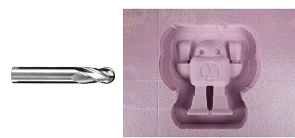
End Mill
End mills are the most common milling cutters. End mills are available in a wide variety of lengths, diameters, and types. A square end mill is used for most general milling applications. It produces a sharp edge at the bottom of pockets and slots.End mills have cutting surfaces called flutes. The most common end mills have two to four flutes. Generally, fewer flutes evacuate more chips from your material, keeping the bit cool. However, more flutes produce a finer edge finish. There are four basic flute types, each optimized for different materials and edge finish.
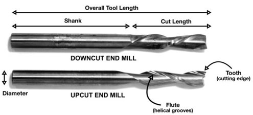
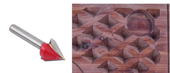
Upcut and Downcut End Mill
These spiral, flute-shaped end mills either carry chips up and away from the material or down into them.
Source~ makezine.com
Procedure to Follow for milling
-Consider tolerance
-Put the drawing in layers as per the cutting scheme
-Arrange pieces to minimize material wastage
-Leave ample distance between pieces to avoid overlap
-Choose the orientation of the bit
-Check all parameter
-See the preview in 3D
-Turn on the machine
-Turn on the exhaust
-Rotate spindle if not used for more than 12hrs to ensure flow
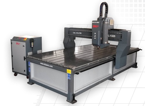
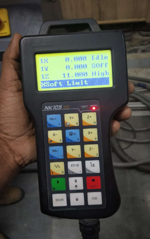
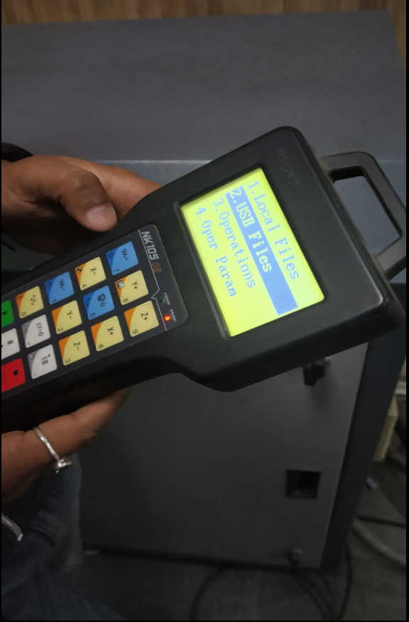
-In my case for SIL Router else in Shop Bit U need to import G-Codes
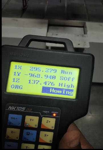
-Do Homing
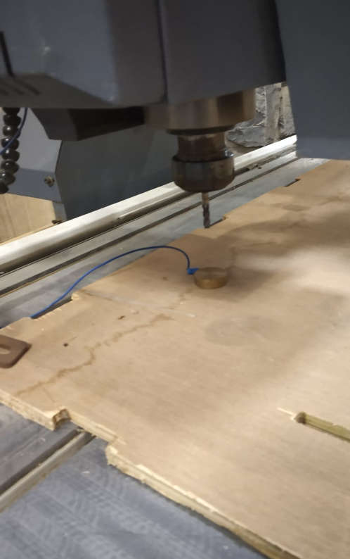
-Calliberate the Z
-Load the file
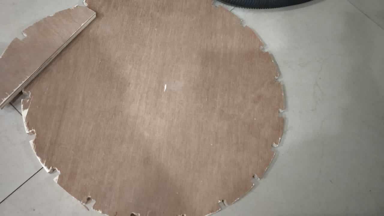
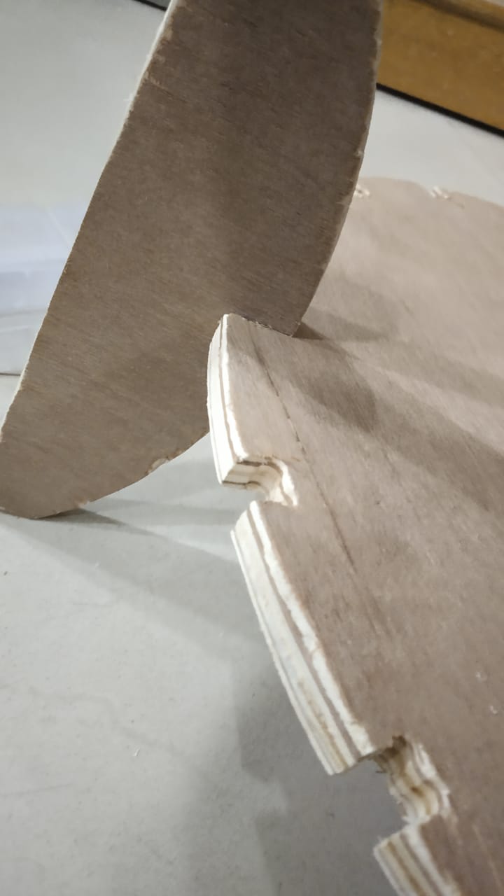
-Start Milling

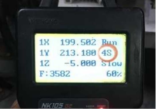 Spindle speed
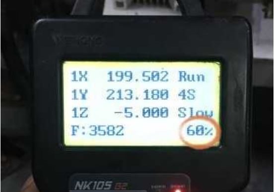 Cutting Speed
.jpeg)
.jpeg)
.jpeg)
.jpeg)
.jpeg)
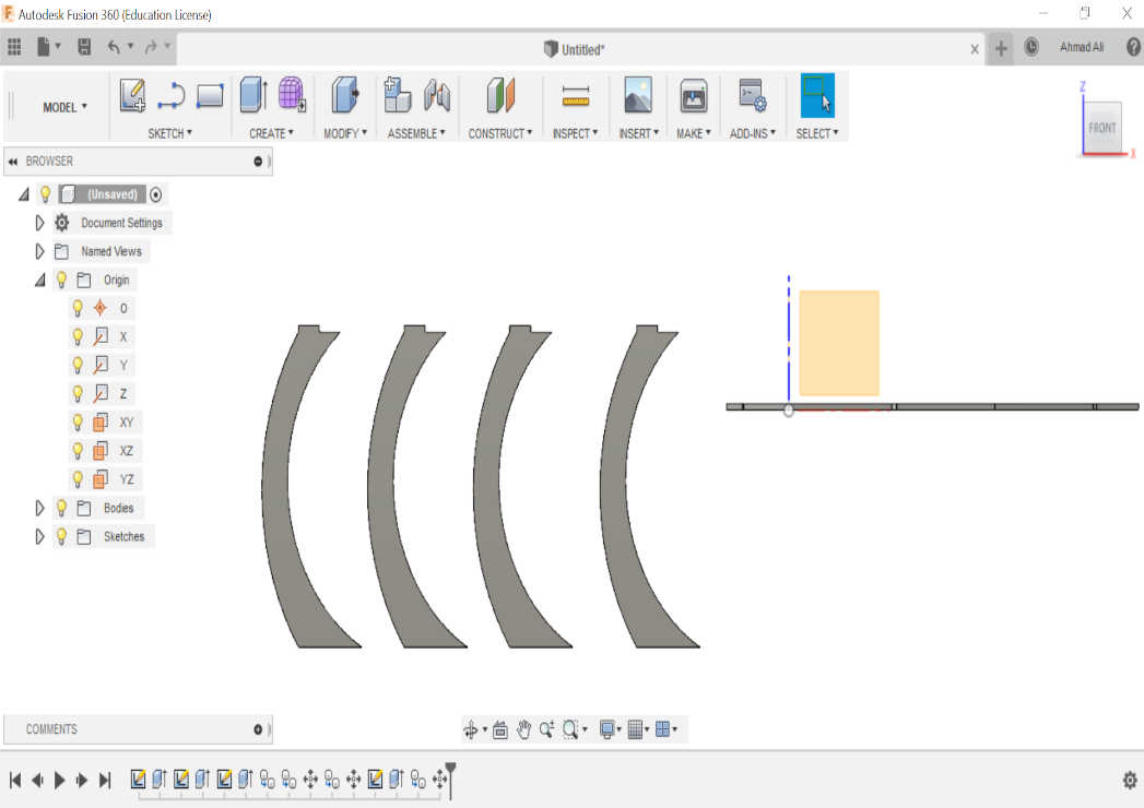
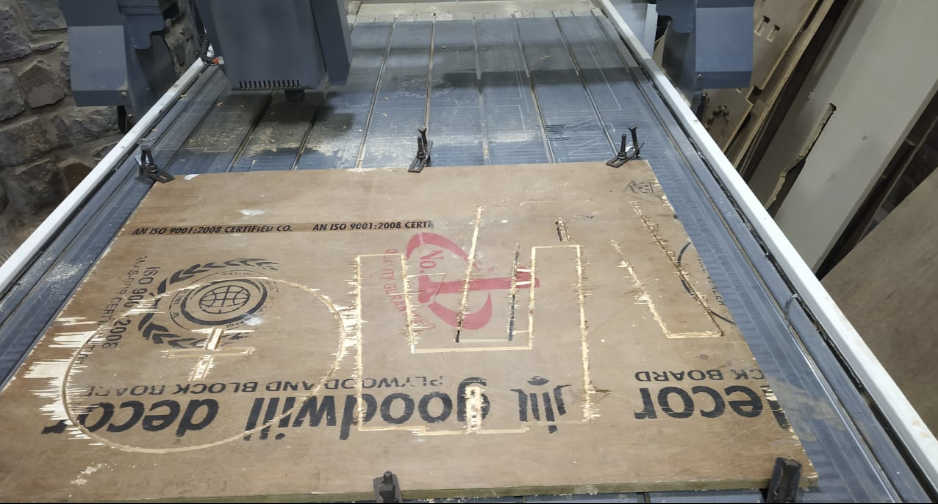
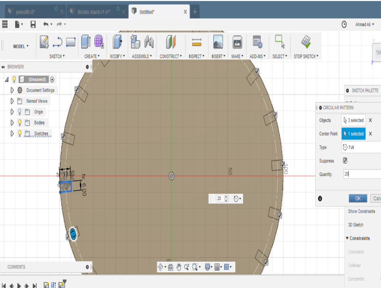
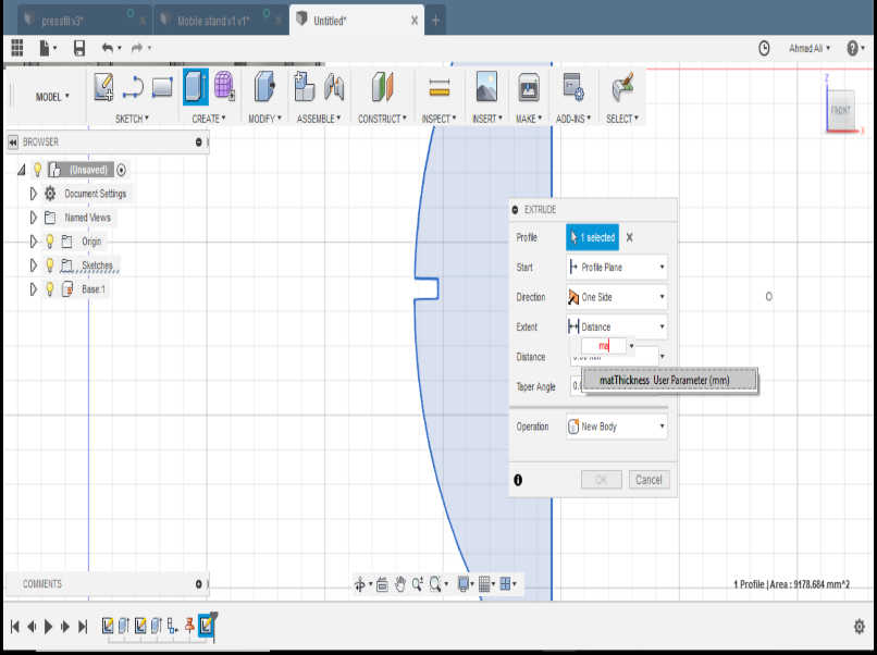
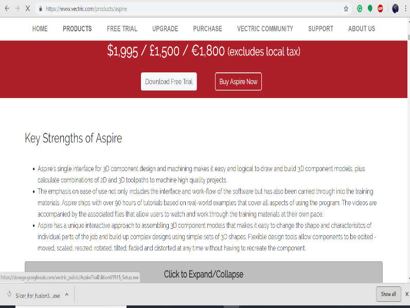
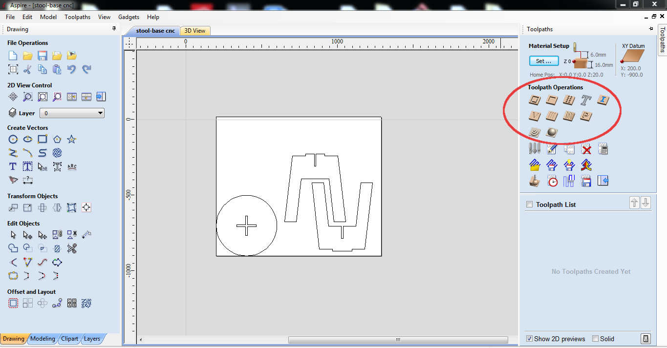
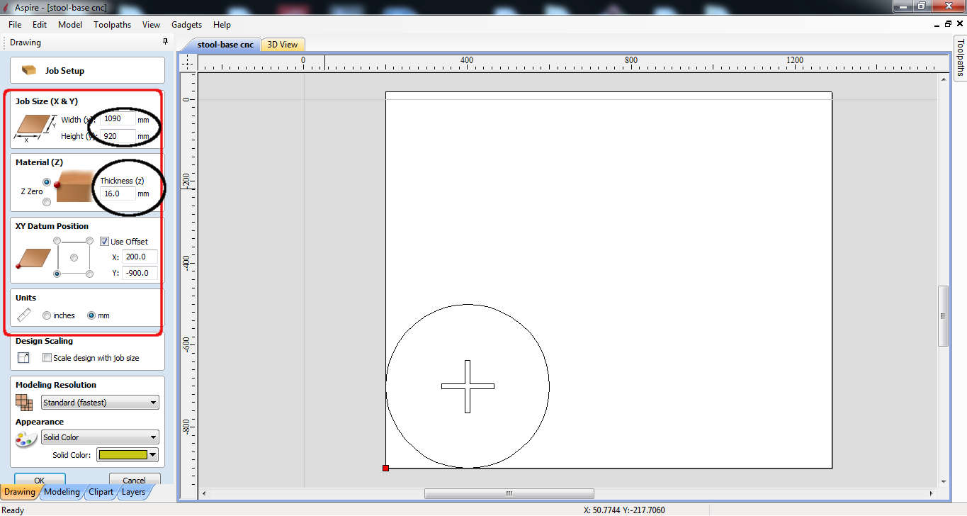 First select the Job Size which is the peice of wood that you have enter the dimension to save the material in y case it was 16mm plywood with 1090x920 mm dimensions as shown in red box.
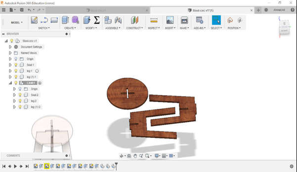
 Then import your vectors the dxf files that I've save and if there are any open vectors join them manually by selecting the vector and selecting the join vector option from bottom left tool bar. I did not needed it although, it's a good practice.
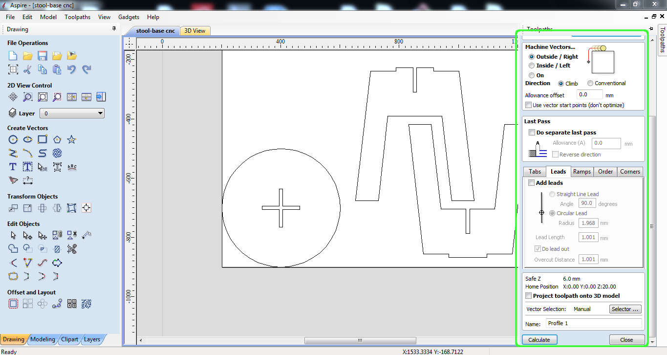
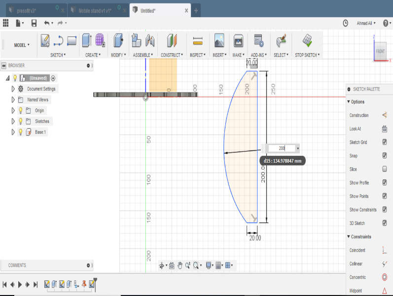
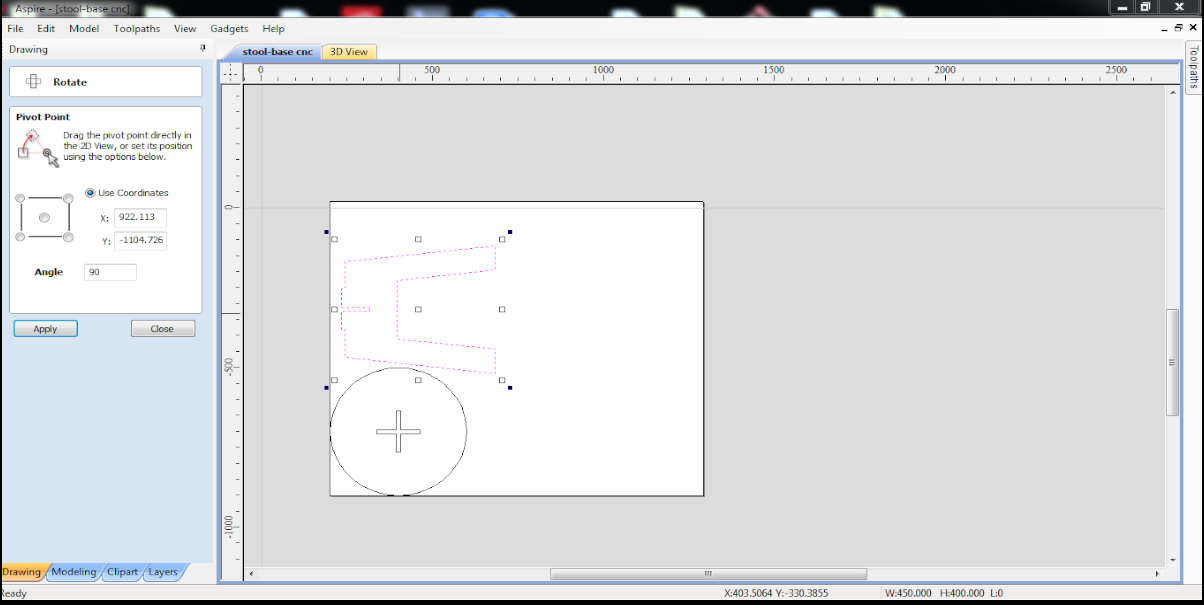
 and circle to be outside
 .
.