Input devices in general
There is a really wide range of input devices to measure: photocells, accelerometers, temperature sensors, color sensors and a lot more. They also come in a wide variety of kits. From the raw sensor to breakout boards with ICs on it to get an easier communication. So for raw sensors, you might get to read an analog voltage and transform it to the value you want in your microcontroller. For sensors with ICs, you might get to communicate with the sensor board with SPI, I2C, UART, just a digital signal or somehow else.
The PIR sensor
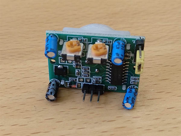
The electronics on the PIR sensor
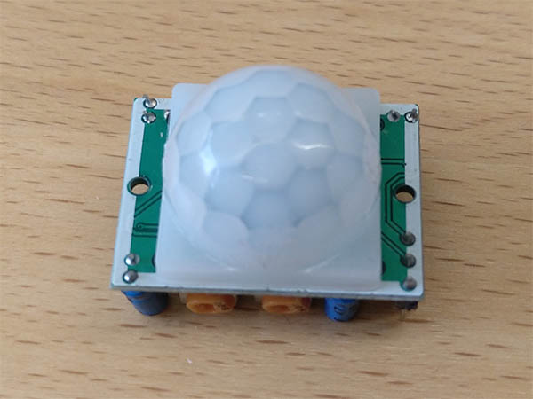
I decided to go with a passive infrared sensor (PIR), which can detect motion by detecting changes in the infrared emission which hits the sensor. I chose the SR-501 PIR sensor, which is already a breakout board for the raw sensor, with a lens which makes the detection just possible and a small circuit to filter the raw sensor output to make it easier to work with the sensor. So the finished sensor board just needs power (5V-20V), a ground connection and has an output pin which yields a high value when motion is detected. Later I realized that the circuitry also brings some problems, which I will explain later.
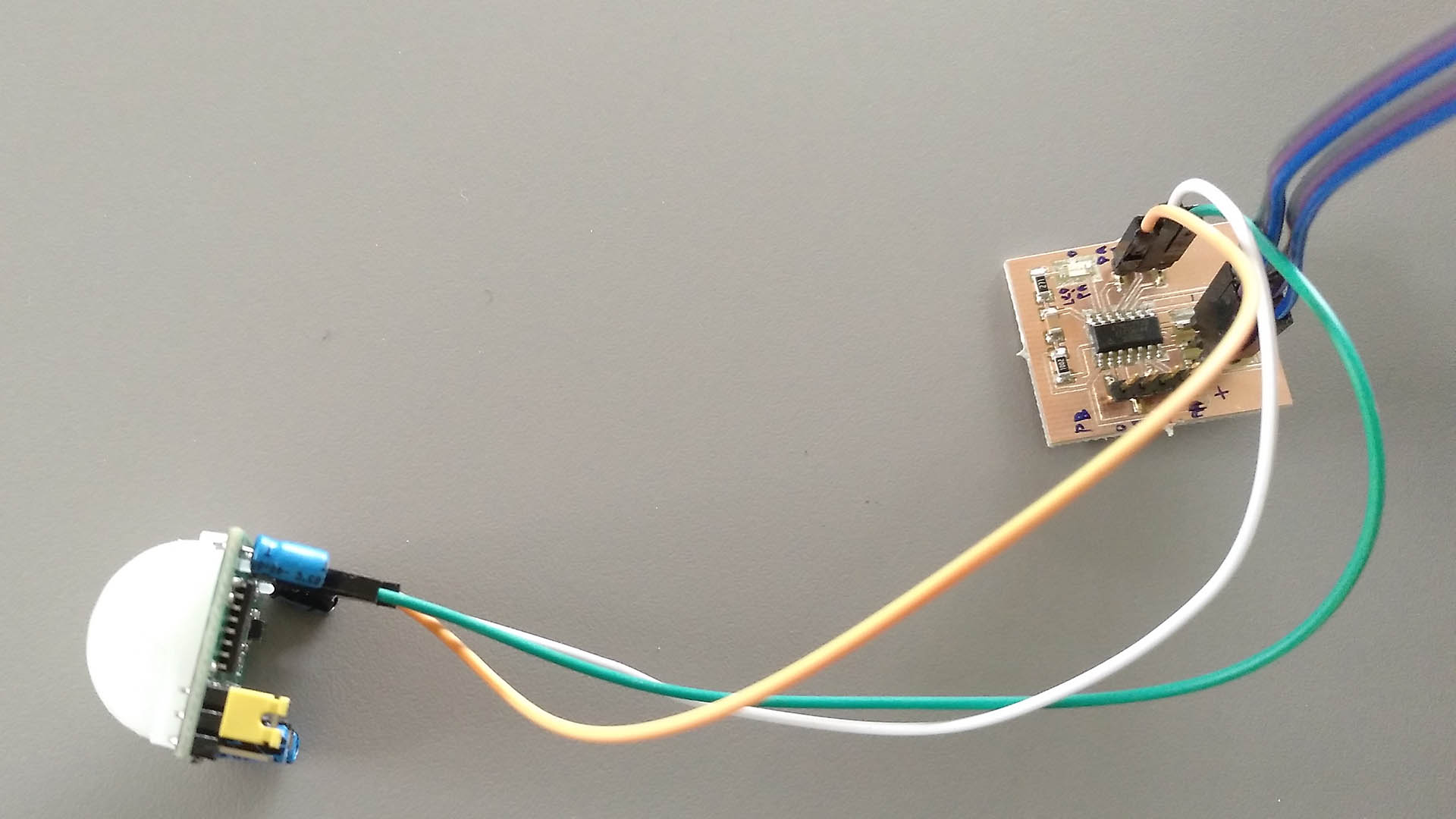
In the group we hooked up another pir sensor to the oscilloscope and looked at the digital and analog output. To look at the analog output we soldered small wires to the raw pir chip (in the middle of the board). Using the oscilloscope in our lab was described in the electronics design group project. On the oscilloscope it was easy to see that the digital signal is very easy, while the analog one was fluctuating a lot. On adafruit there is a great tutorial that explains in detail how the pir sensor works and what the chip is doing. So I am happy that the pir sensor is delivered with the breakout board, so that you don't have to implement all this by yourself. But at the same time using the raw sensor would allow you to tune the detection very much to your use scenario. So if you only want to trigger if there is a very big change over a long time, this might be achieved by using the raw sensor.
Creating the board
I decided I want to use the ATTiny44. But different from the last time, this time I wanted to create a "breakout board" for the attiny so that I could use all pins, even if I didn't need them right away. This is something I learned from the last board, where I could not use the attiny for anything else than the planned thing. Now I can reuse it in any kind. I put on: The header for ISP programming. A capacitor to shield the ground wire from voltage fluctuations. A LED to have an easy way to display any information I want. All unused pins of the attiny are routed to a header on the outside of the board so that I can connect the attiny to anything I want. I attached the eagle files at the bottom of the page.
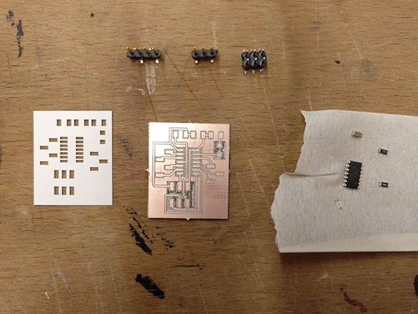
All parts for the board
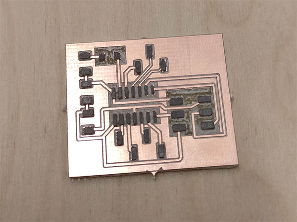
The board with solder paste applied
Then I went on to create it. For more information on how to create the board, mill the board, create a solder mask and solder using solder paste please refer to my extensive tutorials on electronics design and embedded programming. It worked out really good this time and was not much a problem to finish the board.
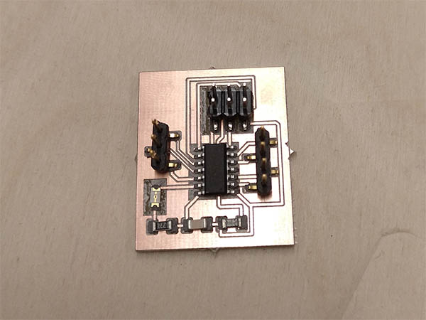
The finished board
Programming
Before I hooked up the PIR to the attiny, I wanted to make sure that it is safe and I don't destroy the attiny when drawing too much current. According to the seller, the PIR has a rest current of 65 uA. The attiny44 datasheet lists under electrical characteristics that the maximum current per I/O pin is 40mA, so it should be safe to use the attiny for powering the PIR sensor. I programmed the attiny using plain c and the USBTinyISP. Details on the programming environment can be found in the embedded programming week. The finished program can be downloaded at the bottom of the page.
Now we are coming to the programming part. Here is a nice tutorial on I/O ports with AVR-GCC in German. At first, we define on which port we can find the LED, the data of the PIR, and which pin we want to use for VCC and GND for the PIR.
#define LED_PORT PA0

#define VCC_PORT PA1
#define PIR_DATA_PORT PA2
#define GND_PORT PA3
First, in the main function we need to set the direction of the ports if we want to read or write data there. Also, we set the pins used as VCC and GND to output the corresponding level. But beware: This is only possible if the device you attach doesn't need much current, otherwise you will destroy the attiny.
// Set the LED port number as output.
DDRA |= (1 << LED_PORT);
DDRA |= (1 << VCC_PORT);
DDRA |= (1 << GND_PORT);
// Set ports as input
DDRA &= ~(1 << PIR_DATA_PORT);

//Init VCC and GND for the PIR
PORTA |= (1 << VCC_PORT);
PORTA &= ~(1 << GND_PORT);
The main loop of the program is just waiting until the input on the data pin is high, then it is activating the LED and waiting shortly. Afterwards, it is waiting until the input on the data pin is low again and then it turns the LED off. Pretty simple.
while(1){

    while ((PINA & (1 << PIR_DATA_PORT)) == 0) {
        ;
    }

    // Set the LED bit to "1" - LED will be "on".
    PORTA |= (1 << LED_PORT);

    _delay_ms(50);

    while ((PINA & (1 << PIR_DATA_PORT)) != 0) {
        ;
    }

    // Set the LED bit to "0" - LED will be "off".
    PORTA &= ~(1 << LED_PORT);

    _delay_ms(50);
}
Problems
One big problem I realized when working with the sensor is the lots of electronic that it is already connected to. Only getting a digital output signal doesn't yield too much information. Also, the PIR will give out a high level for 3s-120s continuously after the detected movement is stopped. This might be great for using only the PIR to turn on a light but doesn't give exact movement information. Also after the signal went to low, there is a 5s dead time, where the PIR won't give any signal, even if something is moving in front of it. This is something that can only be fixed with a different PIR sensor or reading the analog sensor on the board directly.
The finished board
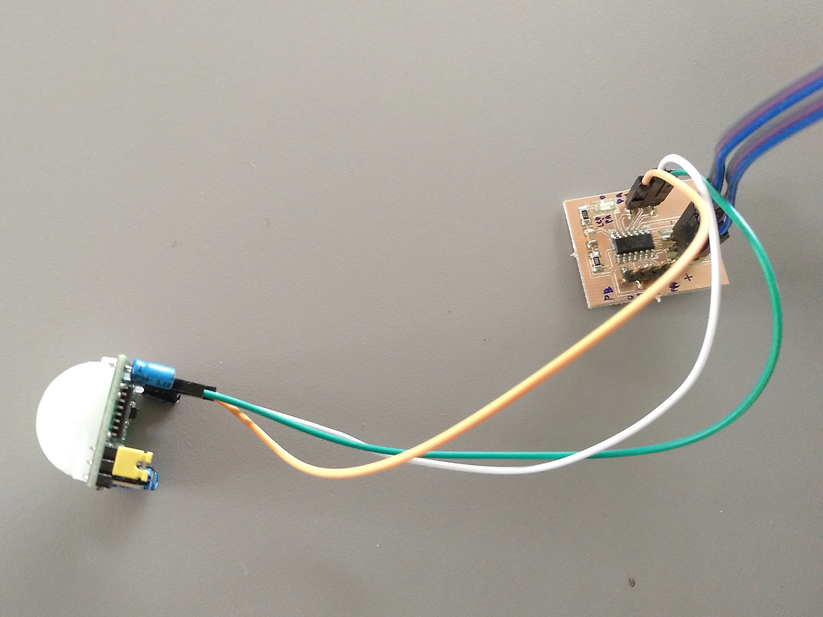
Demonstration
Here you can see the board in action.
Files
Here you can download the files created during this week:
The Eagle files to cut the board
The code to read the PIR and turn on the LED