Computer-aided Design
I have modeled a possible final project and posted it below. It has been made in raster (png), vector (svg), 2D (Inkscape, OpenSCAD), 3D (FreeCAD, Blender) and rendered.
I have evaluated several softwares and selected FreeCAD for both 2D and 3D design. You can see below how I described and used for modeling 2D and 3D objects using those and other softwares.
At the bottom I included my original design files
Basic concepts
2D is in 2 dimensions, length and width. You end up with a flat surface. 2.5D is several succesive passes of layers of 2D, at different parameters in another dimension. So you can get a volumetric shape. 3D is in 3 dimensions. It can create a volumes by traveling simultaneously on the 3 dimensions (not by layers on 2).
I have tested only libre programs for design. Below I mention only those and described the ones I have tested.
There are 2 types of image edition:
- Raster.-
Edition of pixels. Does not modify the resolution.
- GIMP
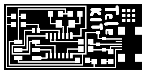
I have used it to edit images of electronic circuit boards
and to change image resolution for the web.
- ImageMagick
It is a command line software. Nevertheless, like all command line softwares, it is very powerful and saves a lot of time once you have a basic idea of its use.
I also used display. It is a graphic interface to the ImageMagick command line utilities. I had trouble using it at first. But once you understand it is very closely linked to the command line, you understand how to use it.
- Vector.-
Edition of lines that form the image. It can handle infinite resolution.
- Inkscape
Inkscape was very useful to transform PCB vector images to PNG which is used by FabModules to transform to Gcode for the LinuxCNC powered milling machine.
- LibreOffice Draw
I did not use it. But it is a simple interface for drawing simple sketches inside an office suite.
- Scribus
It offers the possibility of typesetting and design specially for publications.
- LibreCAD
I have used it thoroughly for 2D. It is very simple to learn.
With LibreCAD I have designed the images of the network topology and of the lines of reflection upon two parabolas from the telecommunications transmitter to the receiver on the final project web page.
- FreeCAD
I have not been able to install FreeCAD on my primary GNU operating system distro: GuixSD. FreeCAD is available on my current GNU distro: Debian GNU. I have made sure not to install non-free software. I was able to use it for making the mold for the Molding and Casting assignment.
- Blender
Blender is a software for 3D modeling, rendering, animation and simulation (view how movement of one or more parts affects other parts) made with a libre license.
I have used Blender to construct the images of the tubes that conduct the light in my telecommunications project. Blender is difficult to understand at first. But if you learn where things are situated and remember the keyboard and mouse bindings, it becomes easy and quick to design on this libre program.
Choosing the objects with the mouse button on the right and non-standard key bindings makes it very different from other programs. Nevertheless, these keyboard and mouse bindings can be customized. The best is just to practice the default bindings.
A view is a key concept to understand in order to get the catch of Blender. The Blender window can be split as many times as you like to make distinct tiled spaces. Each of these spaces holds a certain view. Views are not just perspectives. They can also be parameters, text notes or other things. The important thing is to know that each space can be configured to show a different view. I show some of the different views in the Sverchok section of this web page.
Test designs
World Wide Web consortium public domain parabola in SVG format.

Trying to make a parametric design with Inkscape as instructed by Neil. T
hen noticed the design was not really parametric but rather constrained by the changes made to other shapes.

Light tubes' and component box draft
I decided to make the design of the light tubes and the electronics box for the telecommunications device. So I needed to make 2 cylinders that had a diagonal face in Blender. It did not work.
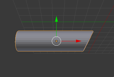
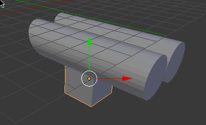
Making the component box.
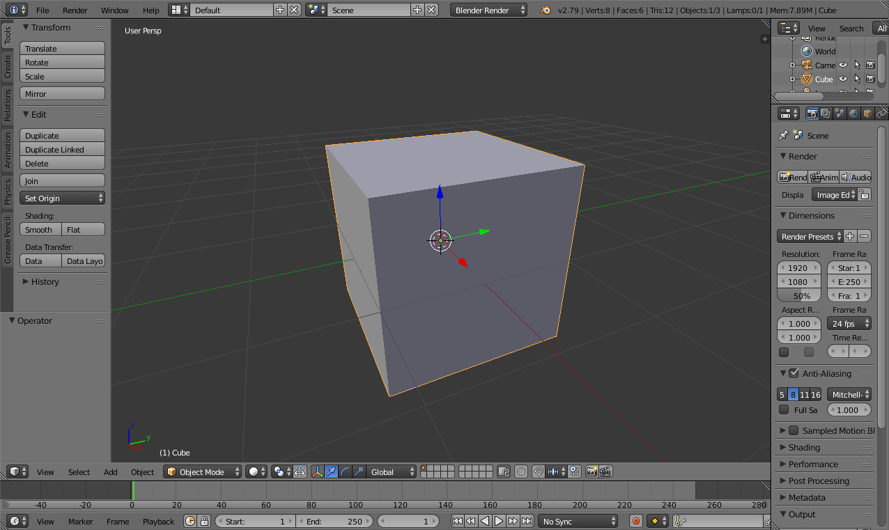
I compressed it with the arrows.
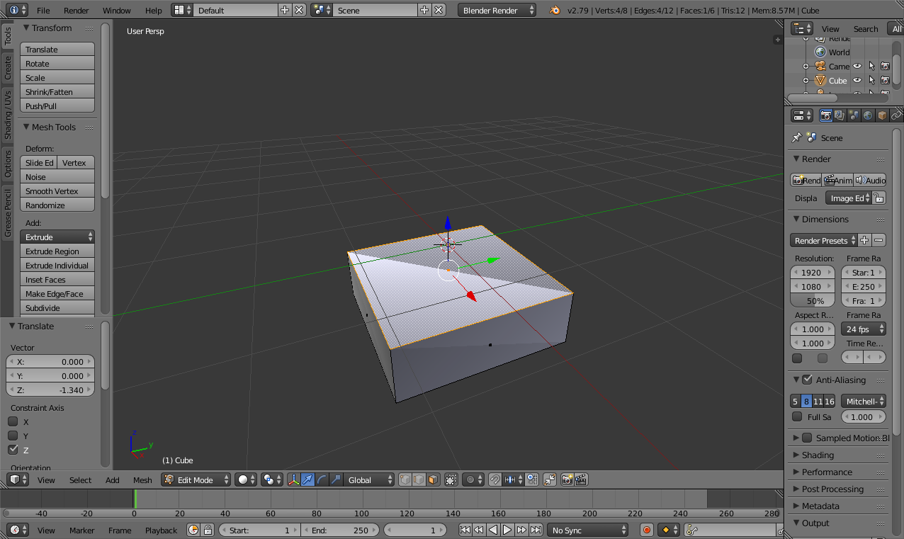
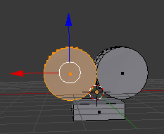
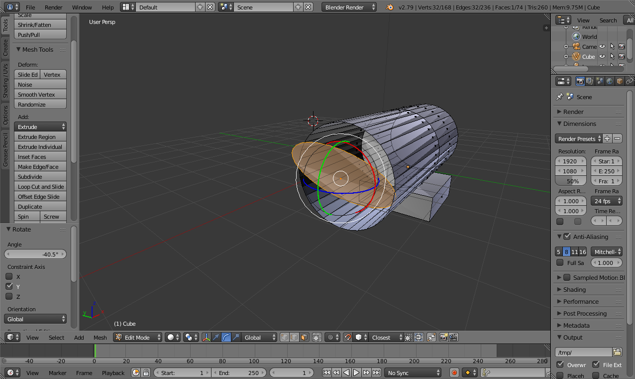
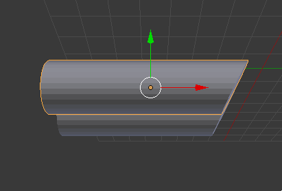
Then I added a cilinder (for conducting the parallel light rays) and stretched it.
And extended the cilinder
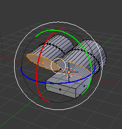
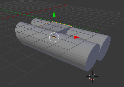
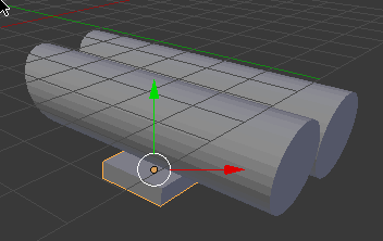
Now I rotated the cilinder in order for it to be parallel to the box.
Then I copied the modified cilinder to make another other exactly as the first.
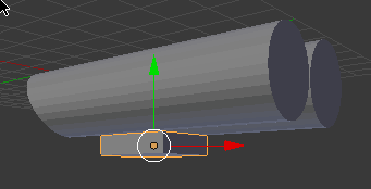
At first I tried to rotate the tube cover. But the tube became deformed and the cover kept its form. That is the opposite of what I intended. I tried to make the caps of the cylinders rotate. But when they rotate, they take mesh of the tubes along with them. So the tubes become deformed.
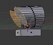
I tested making the cap separately from the tube. But I do not know how to connect objects in order to link and cut the caps along the lines of the tubes.
From here the Blender original failed test file can be downloaded.
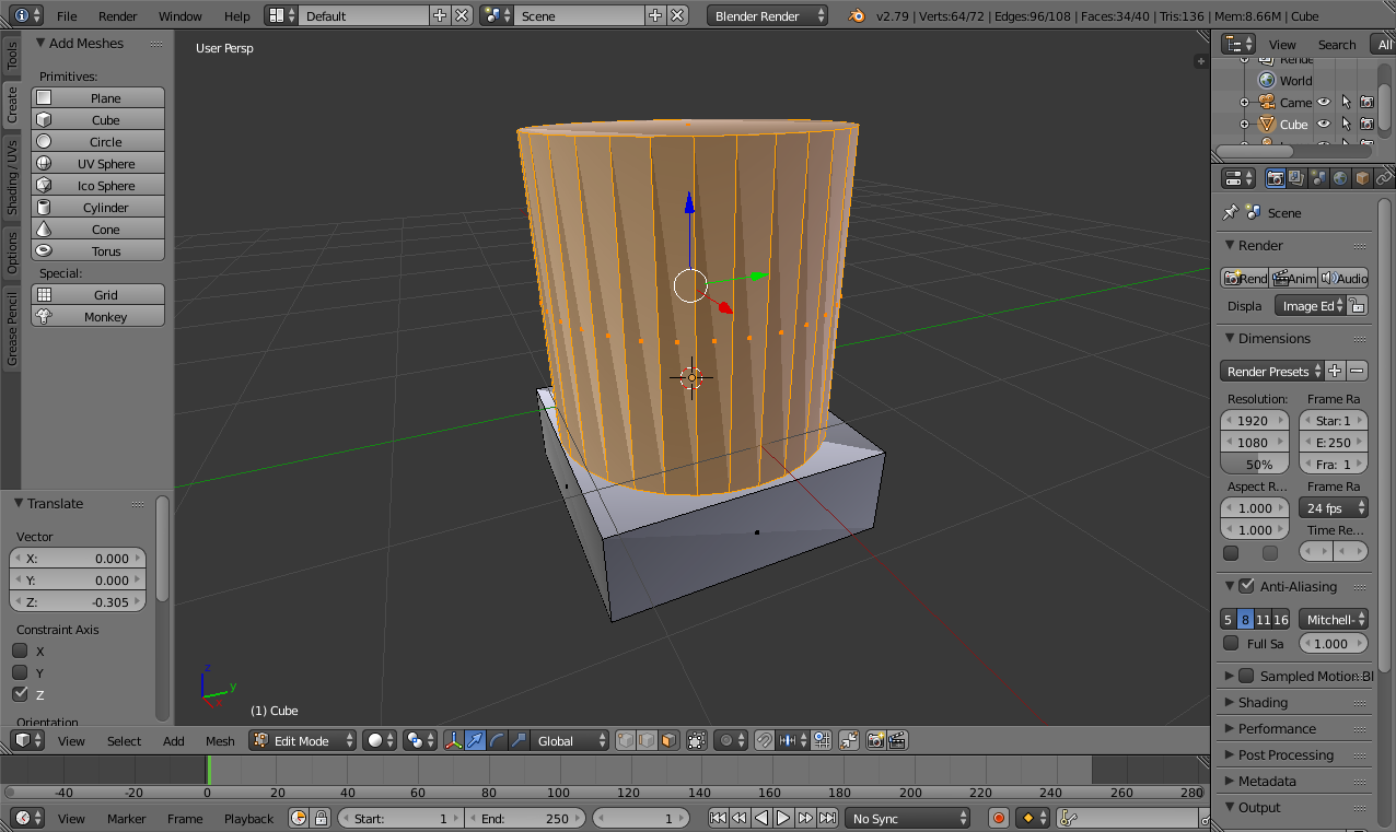
I solved the problem. Below I show how the process is done with faces.
I created a cilinder and a cube.
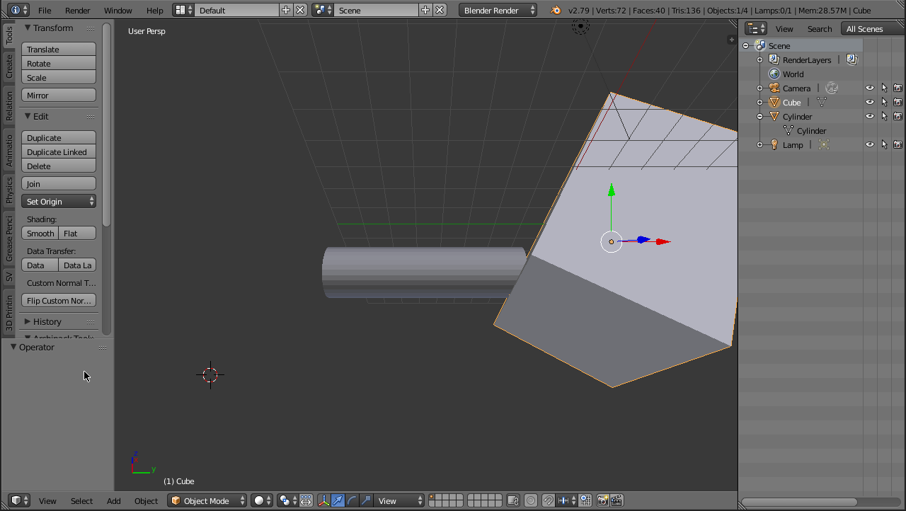
I moved the tube in order to make it intersect with the cube.
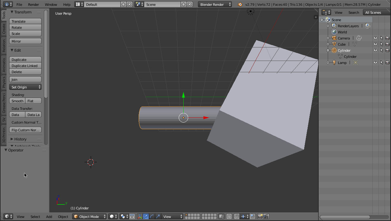
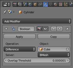
Then I selected the cilinder with the right mouse button. On the right side bottom pane is the Properties view. I chose the object modifier tool, which is the wrench icon. Then I selected the difference operation with the cube.
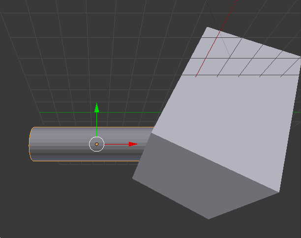
I deleted the cube with the x key and I had the following result.
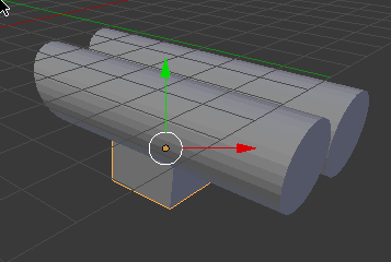
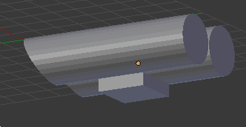
Duplicated the tube.
Created a cube, compressed it and aligned it with the bottom center of the tubes.
In order to create a solid based on a line, it is possible to use the Screw Blender modifier add-on. It can rotate any form to make a solid. Just go to the Modifiers tool on the Properties view and add the Screw modifier. There you can modify the axis to rotate the form on in order to form the solid. When it looks good, you can press the Apply button.
Paraboloid mirror
FreeCAD then Blender
I downloaded the shape of a parabola.
I made the design of the wax cast to mold my silicone rubber cast for the PVC paraboloid pieces. It is designed in FreeCAD.

You can download the original cast 2D FreeCAD file.
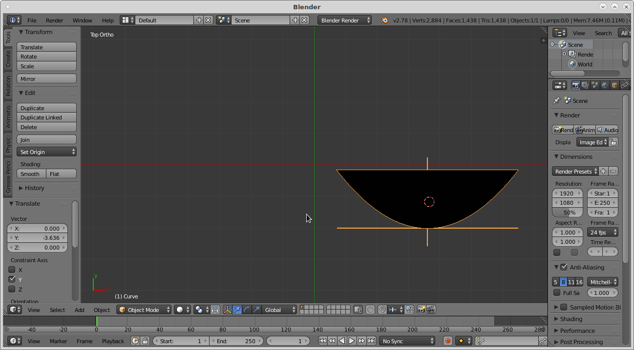
So I exported the piece to SVG in FreeCAD and imported it in Blender to design the temporary 3D cast of the final cast.
I was not able to use it because my figure was composed of several objects. So I joined them with Control+j after selecting all of them. Then, I could use the Screw modifier.
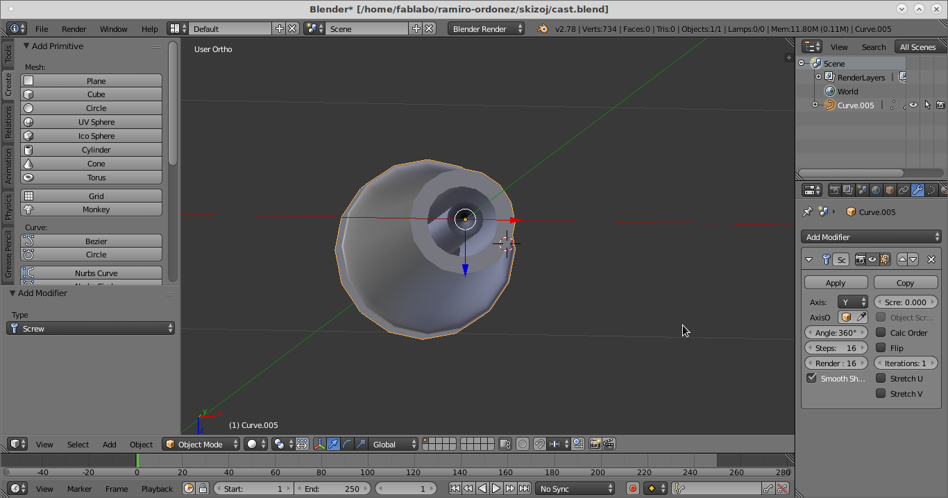
I used the Y axis. But I need the rotation to be on the right side of the figure and not on the left.
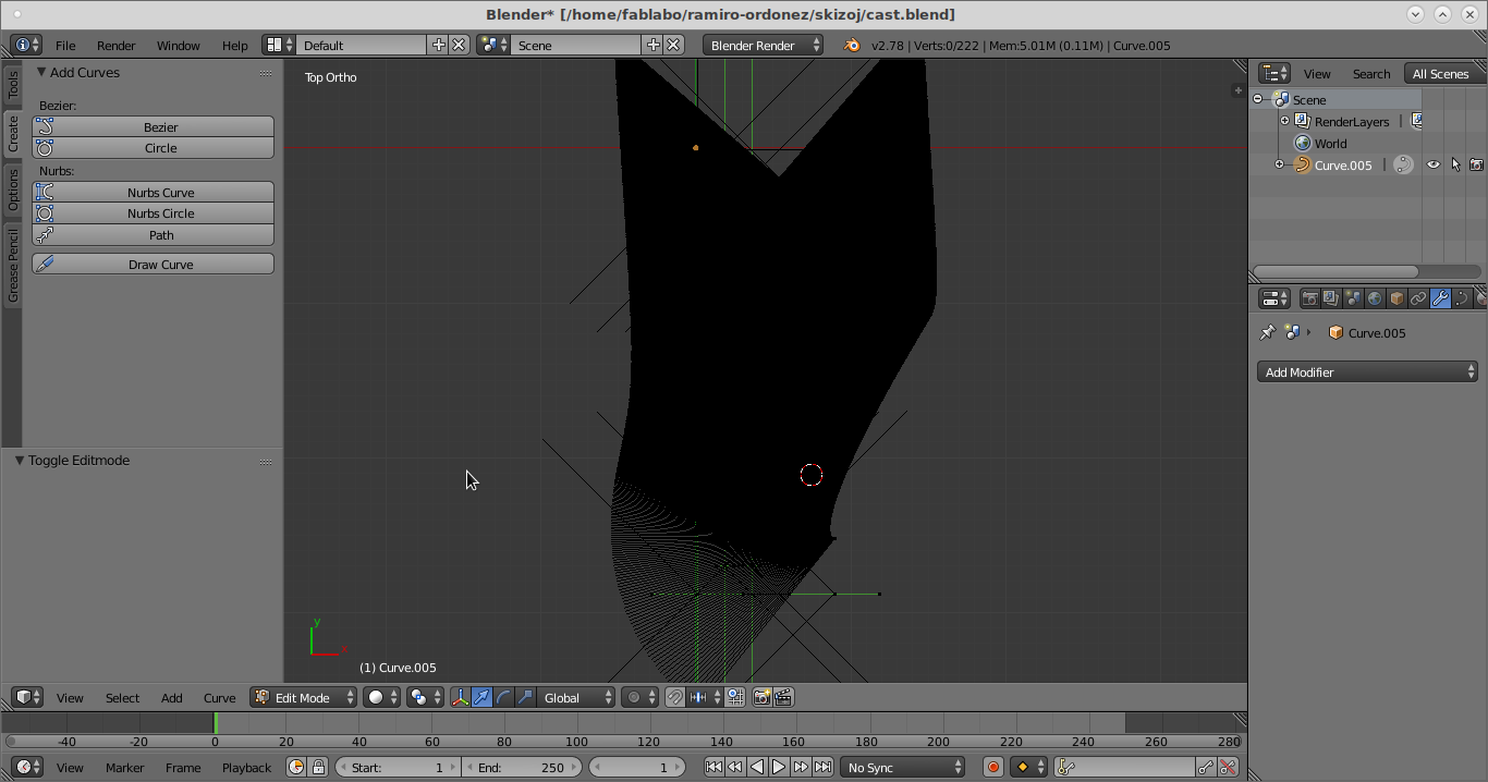
So I changed the piece cursor in order to have the rotation reference be on the right side.

To remove the volume of a solid from another solid, we can use the Boolean Blender modifier add-on. Select with the right mouse button the main solid. Then go to the Modifier tool on the Properties view. Add the Boolean modifier. There you can choose the solid with which you want to remove volume. Choose Difference in order to remove the volume of the second solid from the first solid.
I entered this piece into FabModules and everything looked good.
But LinuxCNC did not accept it.
Sverchok (Grasshopper in Russian) Blender Addon
I am learning Sverchok. It is an add-on for Blender to make parametric design possible.
For studying Sverchok, the tutorial suggests to have the following views open simultaneously:
- On the top you can see the Information view with an i icon.
- Below it you can see the Node editor view.
- Going further down you can see the Text editor view with the notepad icon at the left side and the 3D view with the cube icon at the right side.
- All the way over to the right side of the Blender window you can see the Properties view on top and the Timeline view on the very bottom. (This view is not asked for in the Sverchok tutorial. But it is documented here for better comprehension of Blender views.)
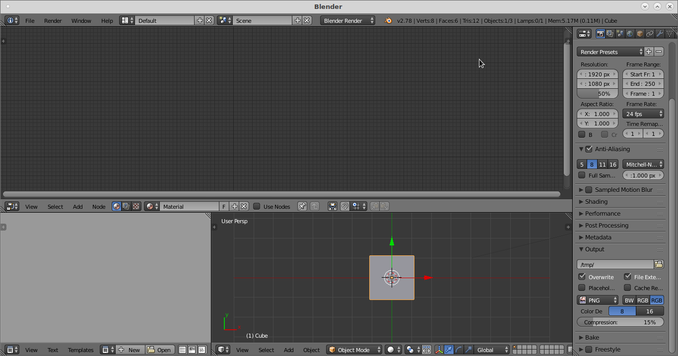
This is an image of Blender with the windows' setup recommended for Sverchok.
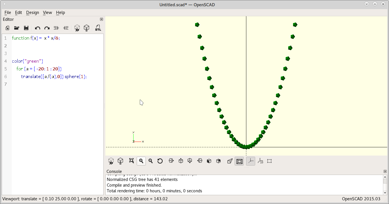
Testing with OpenSCAD
OpenSCAD looks very straightforward. It seems very parametric. So designing with it must be very easy once you know the math to your shapes.
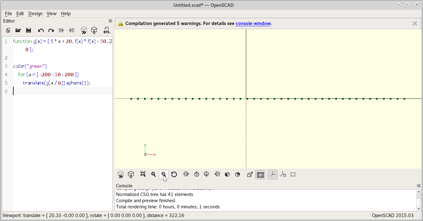
Just a sequence of dots. No function.
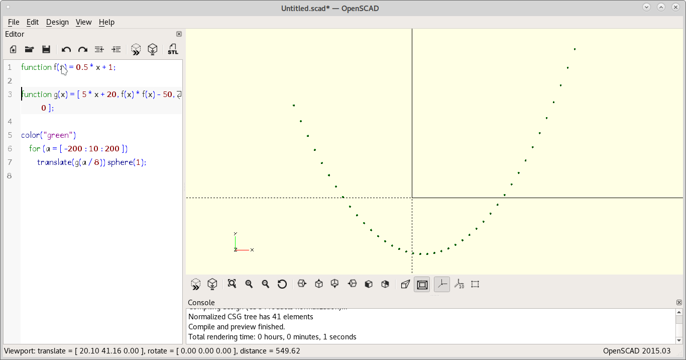
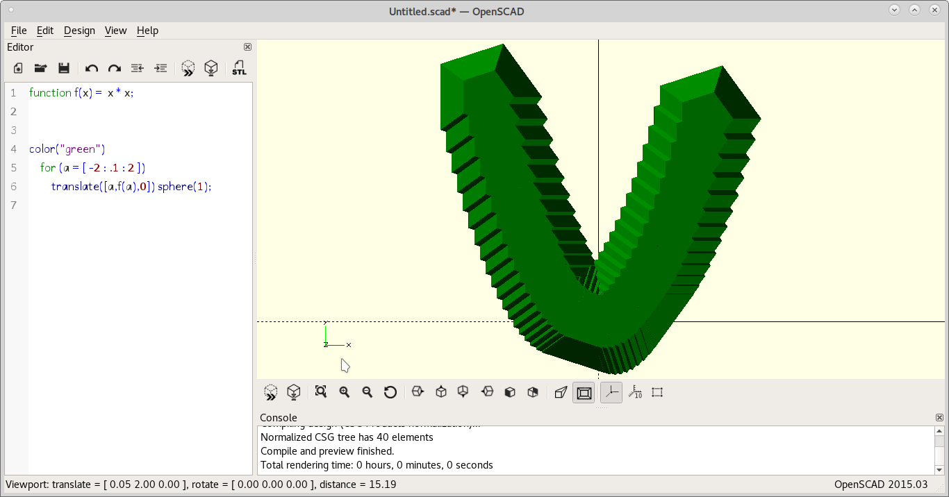
Introduced the formula for the parabola, f(x)
Changed formulas. Woops! An error.
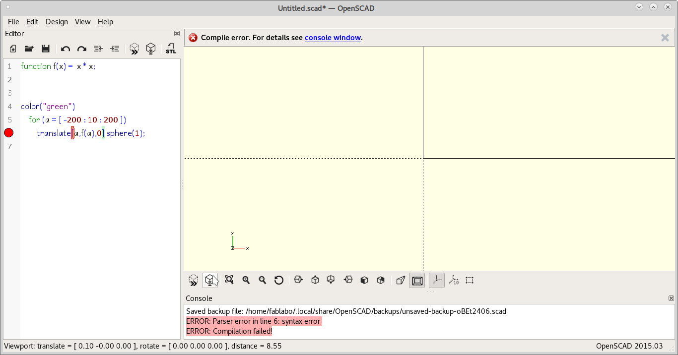
It was a missing parenthesis. Also made the horizontal scope shorter to make the parabola skinier.

And now skinier! But the dot becomes too big. :-D
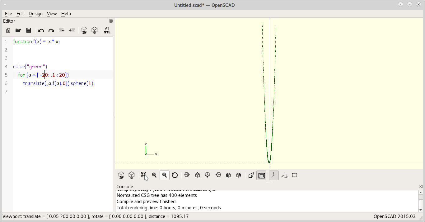
Now a skiny parabola with lots of dots.
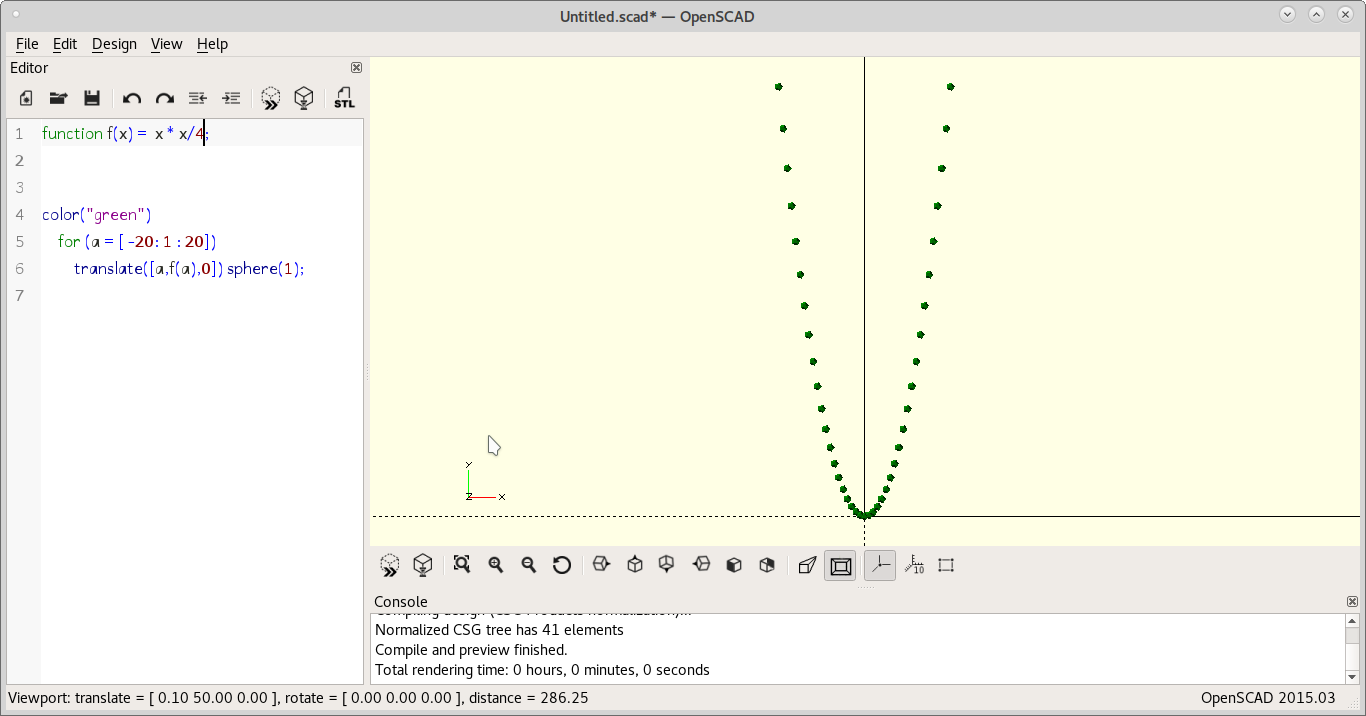
A little fatter with divisor = 4.
Even fatter with divisor = 8.
Thinner dots.
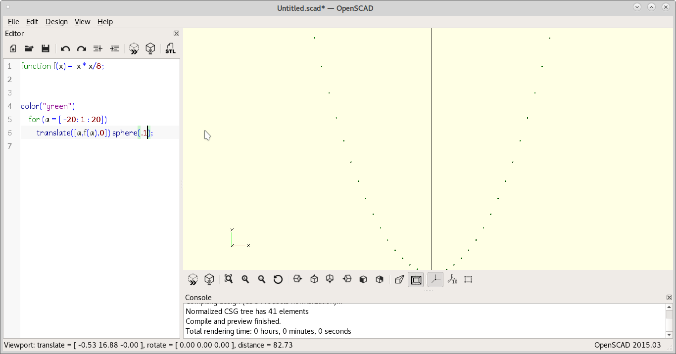
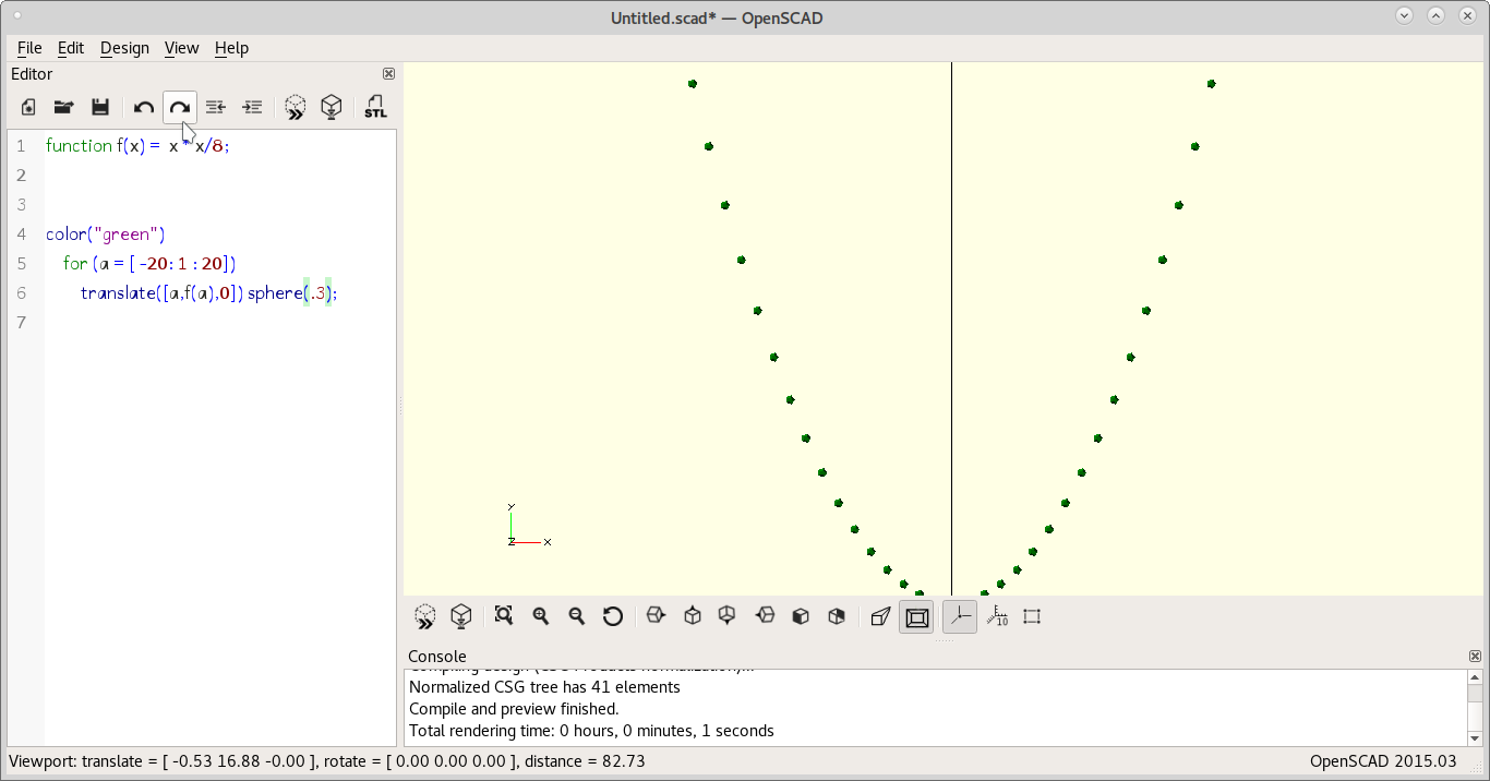
Too thin. Making dots a little fatter. But not too much!
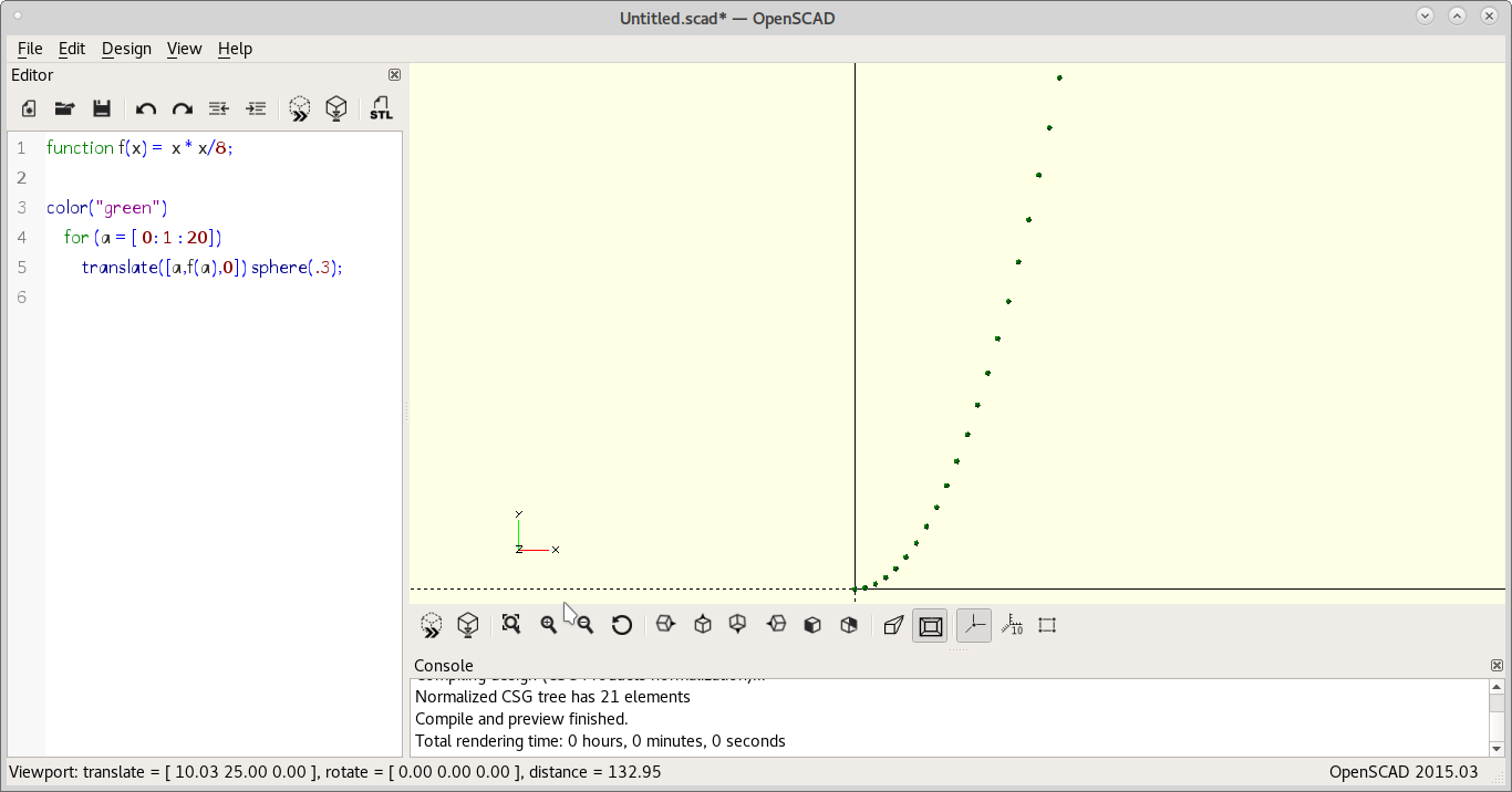
I just need one side. I will revolve it for making a 3D paraboloid.
Here is the source OpenSCAD file.
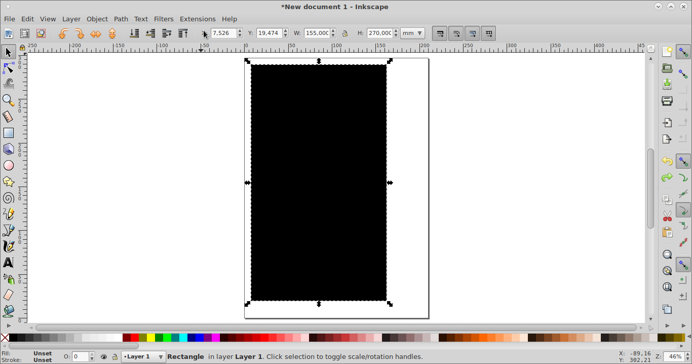
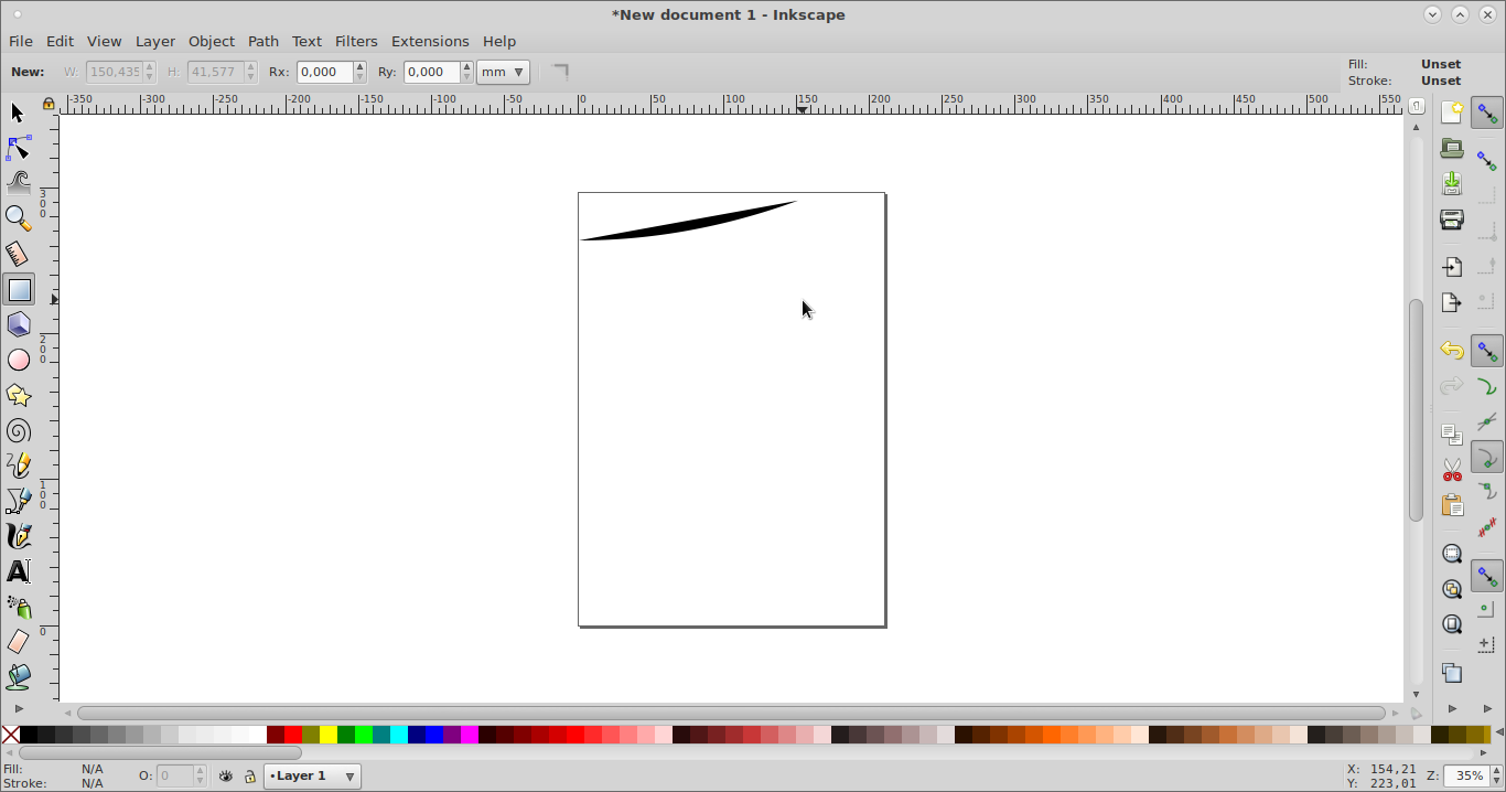
Trying with Inkscape
Drew a square
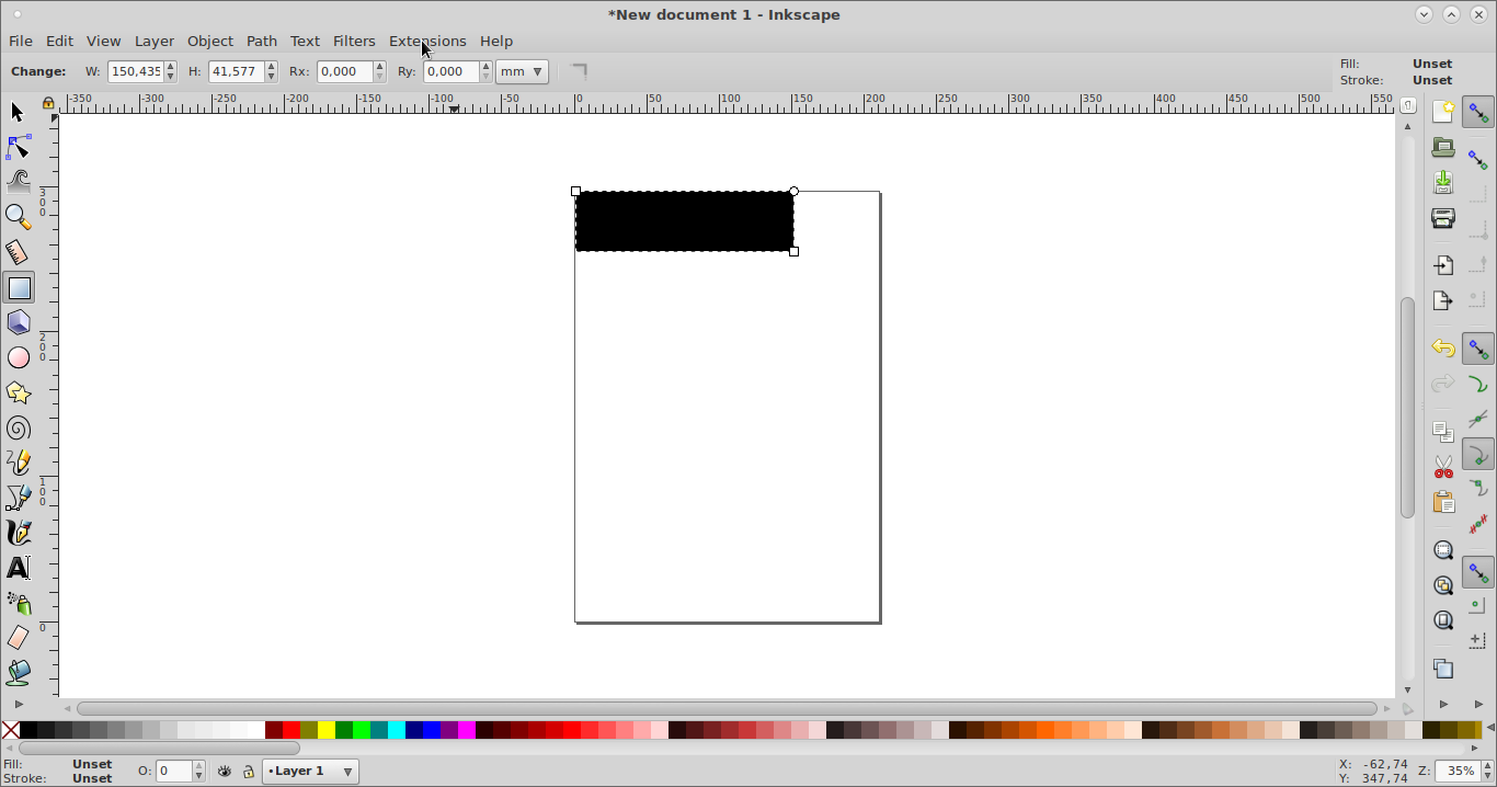
I decided to use Inkscape's Function Plotter from the Render extension.
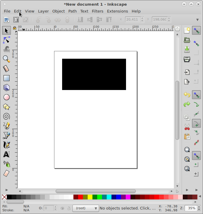
In the menu I chose Extensions -> Render -> Function Plotter

Decimal comma did not work on formula.
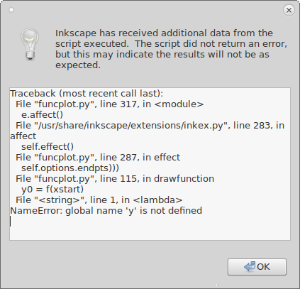
Changed to decimal point

And played with several parameters

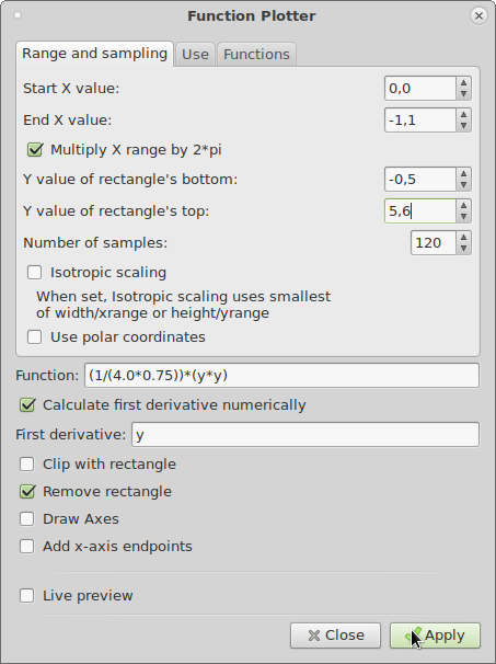
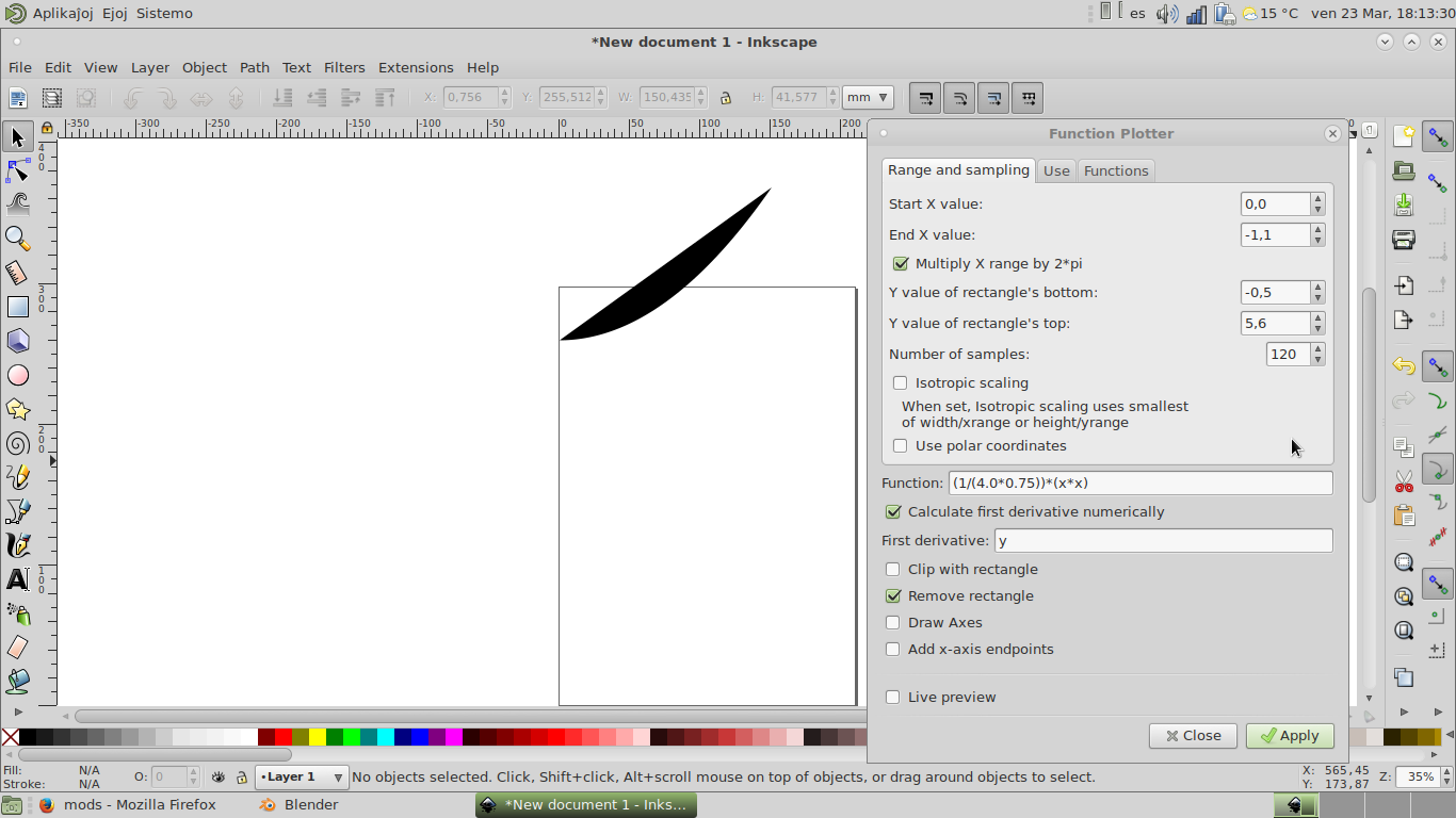
Changes led to the following final shape.
Here is the Inkscape parabola file.
The resulting image drawl with Inkscape.
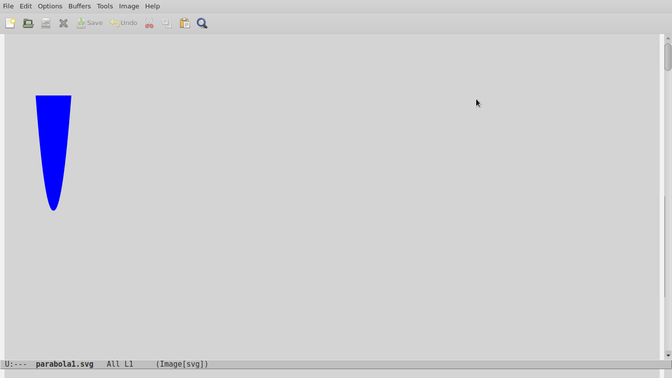
Drew a parabola!
Source file for parabola drawn in Inkscape.
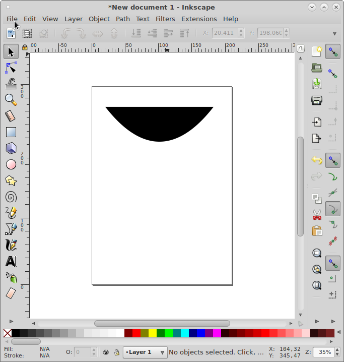
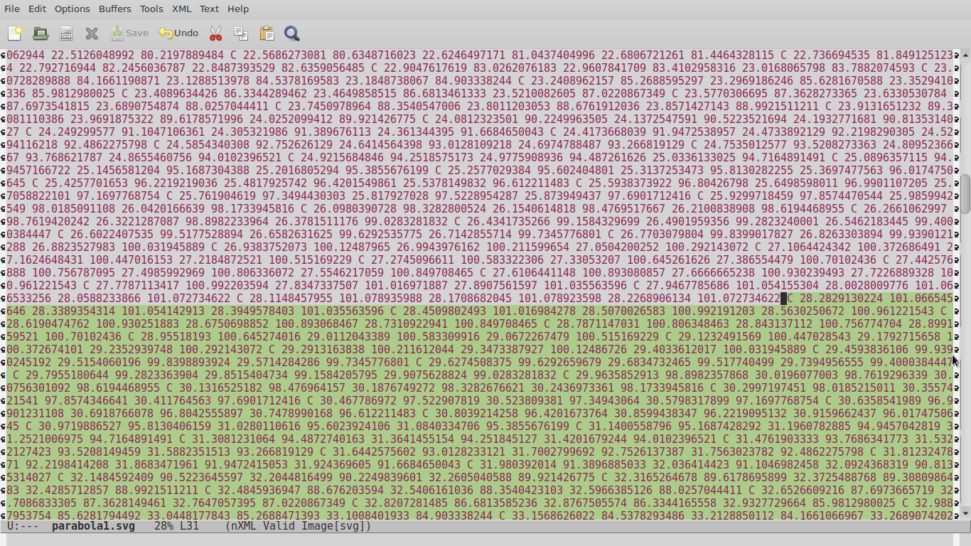
The source code can be edited with a simple non-formating text editor.
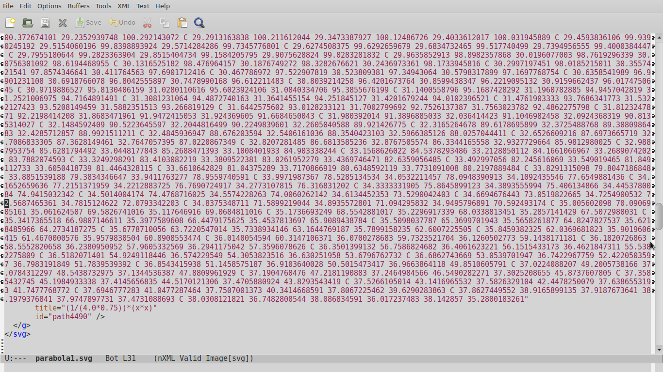
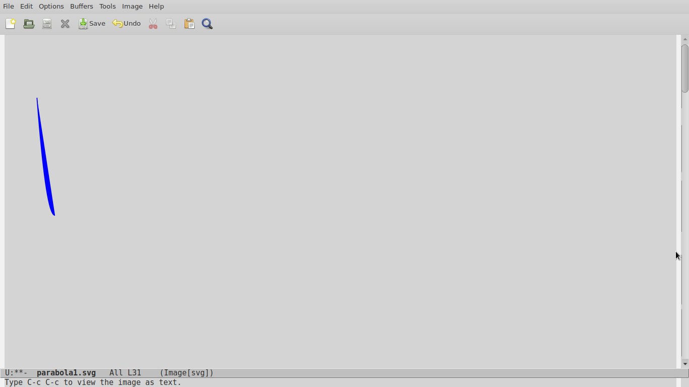
The right side of the parabola is removed from the source code.
This is how the final rotatable half-figure looks.
Back to FreeCAD
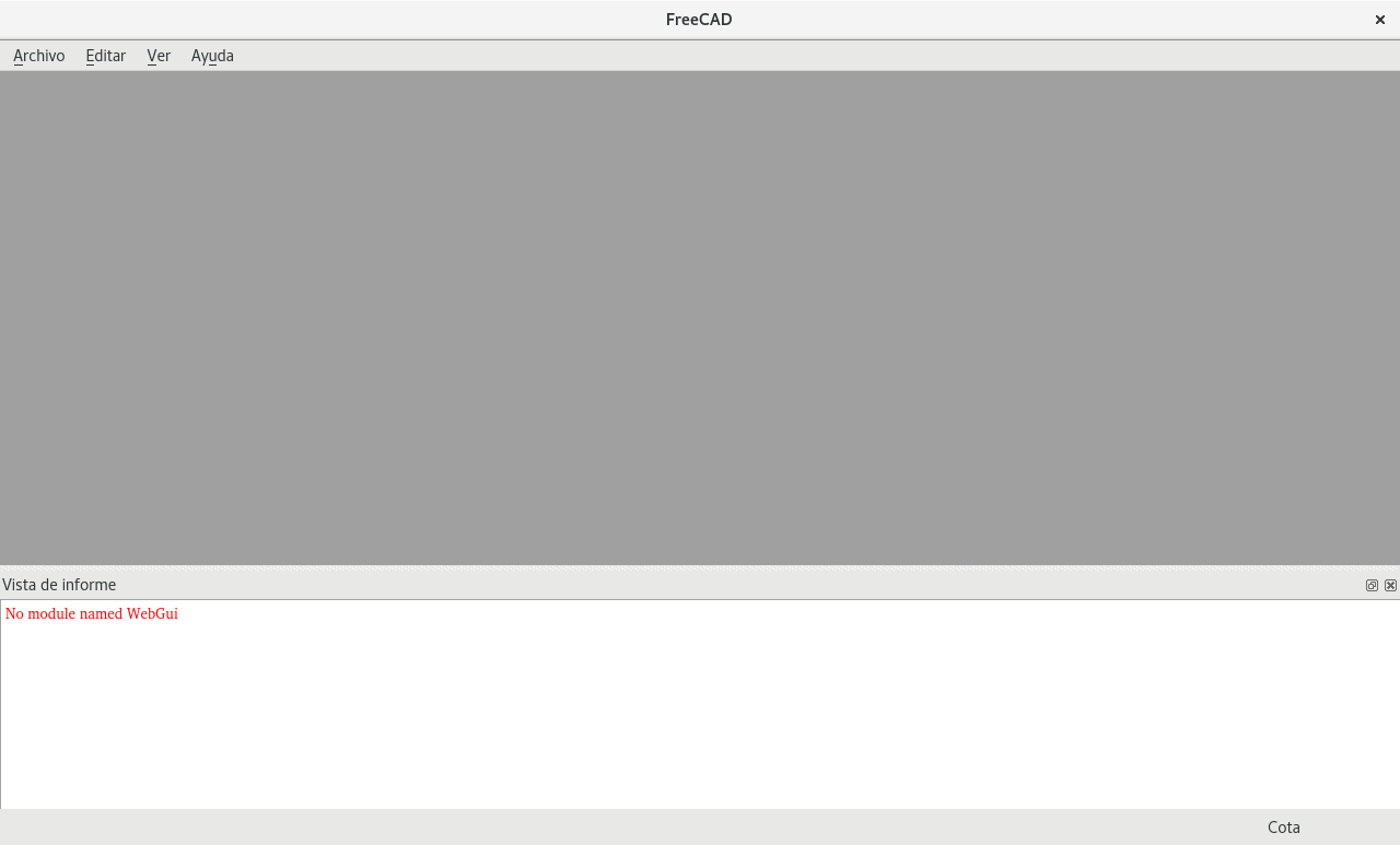
Opening FreeCAD for the first time gives you an unpleasant surprize. It appears broken. It needs Qt4 for showing the Startup page with WebGUI. Debian does not provide Qt4 anymore but Qt5.
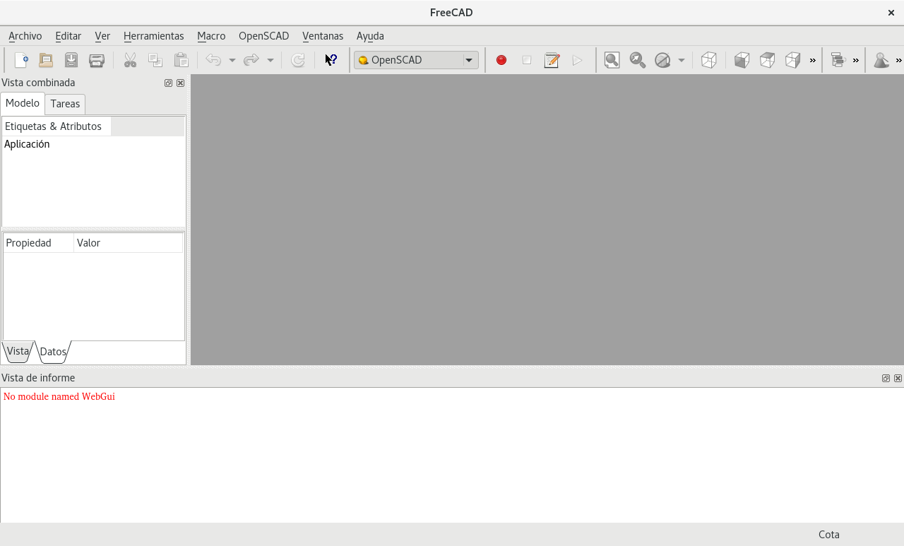
But as soon as you choose another workbench on the view menu, everything looks good. All you lose is the startup page guides connected to the FreeCAD website. Here you can see the OpenSCAD workbench.
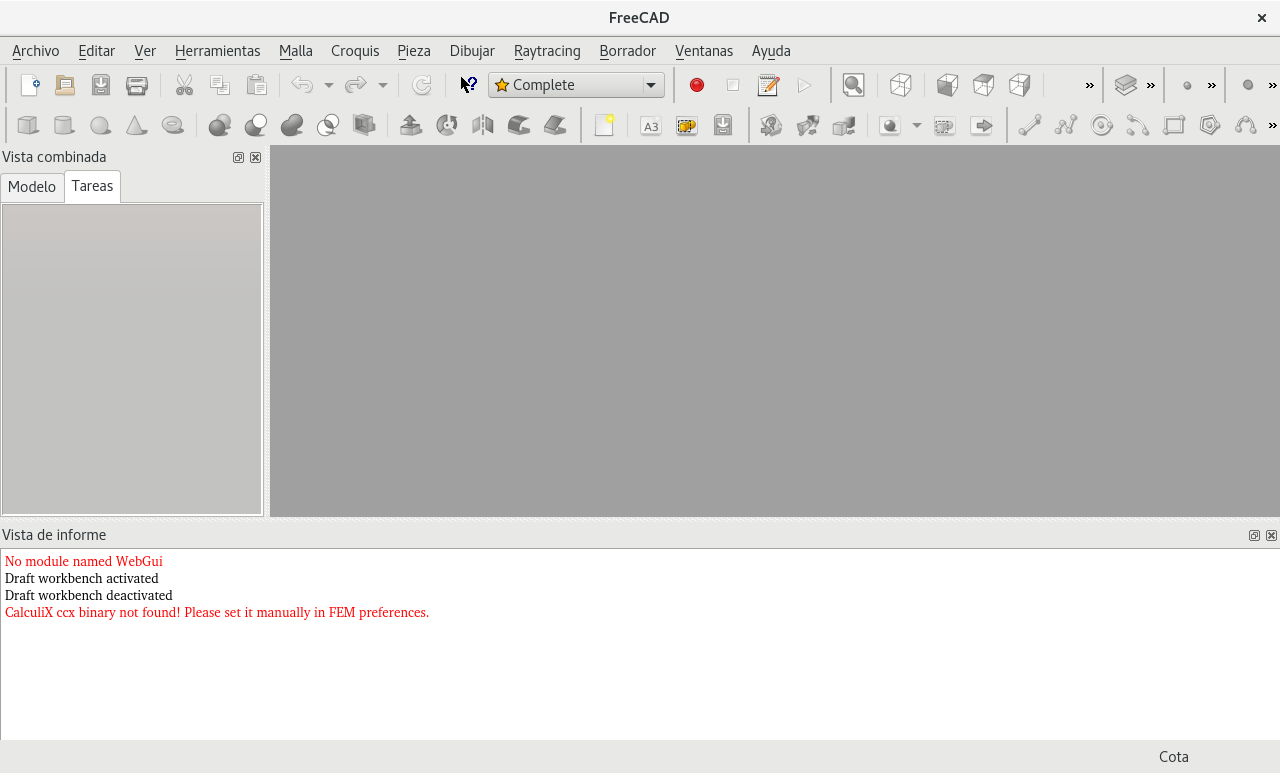
Here is the Complete workbench. Each workbench has a different set of tools for separate jobs to be done.
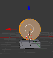
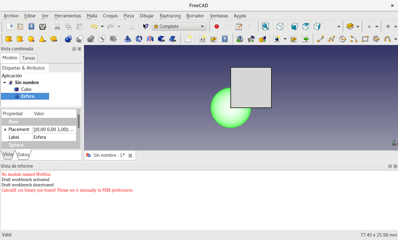
Made a sphere and a cube.
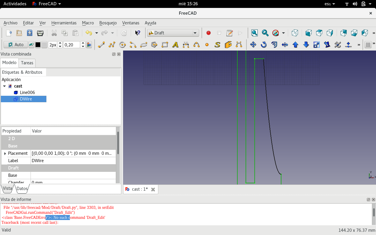
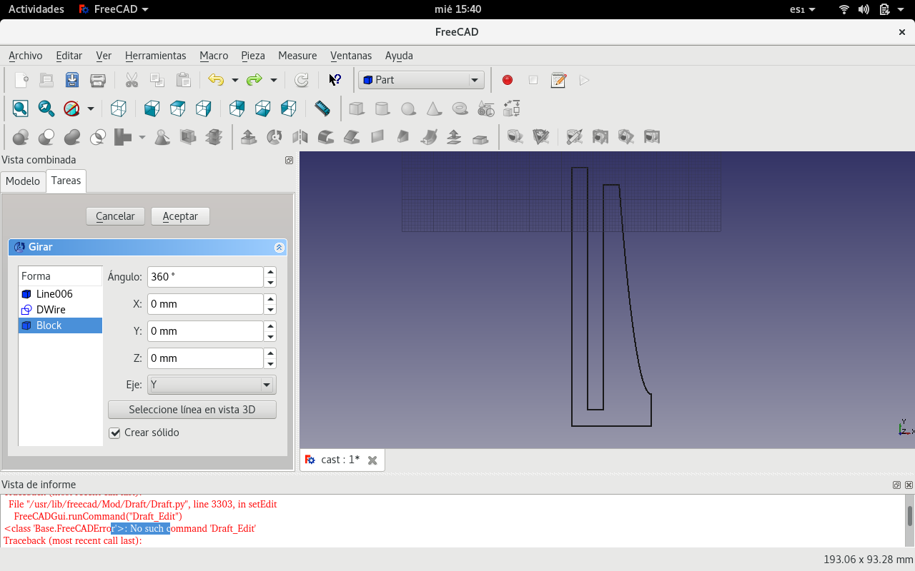
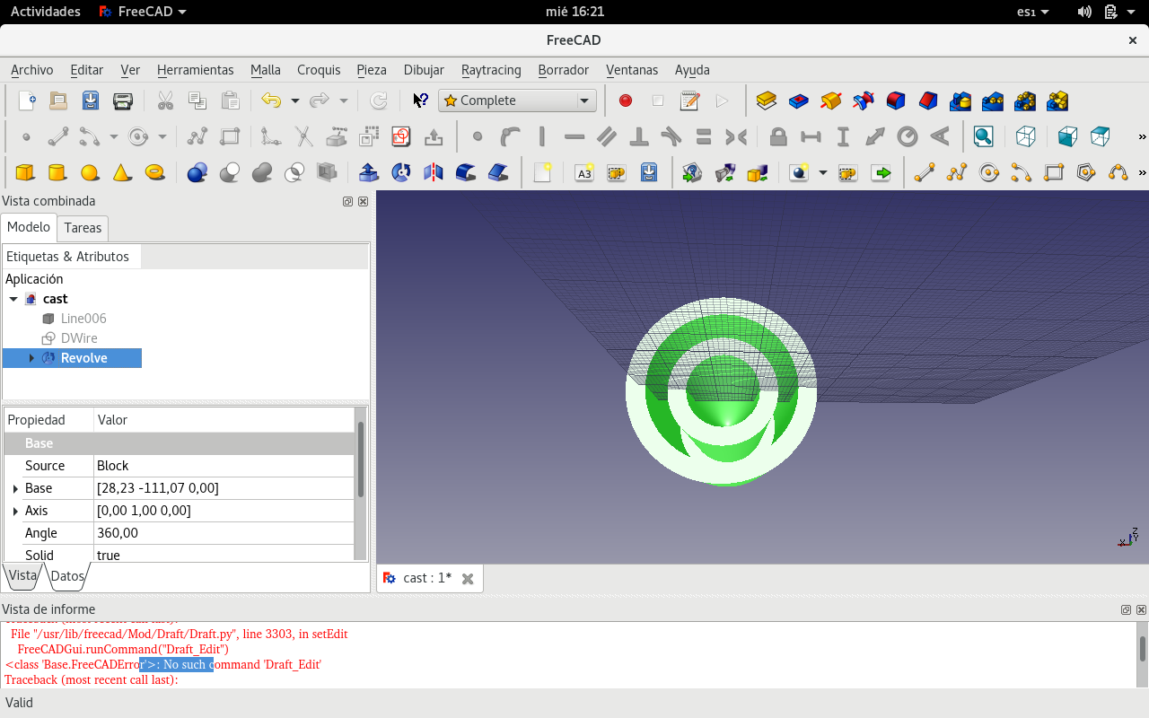
After redrawing the original FreeCAD orthogonal lines in one continuous wire, I could connect the parabola SVG generated in OpenSCAD with the thick UP arrow. Then I selected both objects and used the Revolver function in order to make a solid from the 2D design of the resulting combination of the orthogonal lines with the parabola line.
One object made with all the 2D composing lines
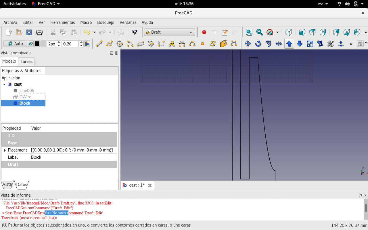
Used the join tool
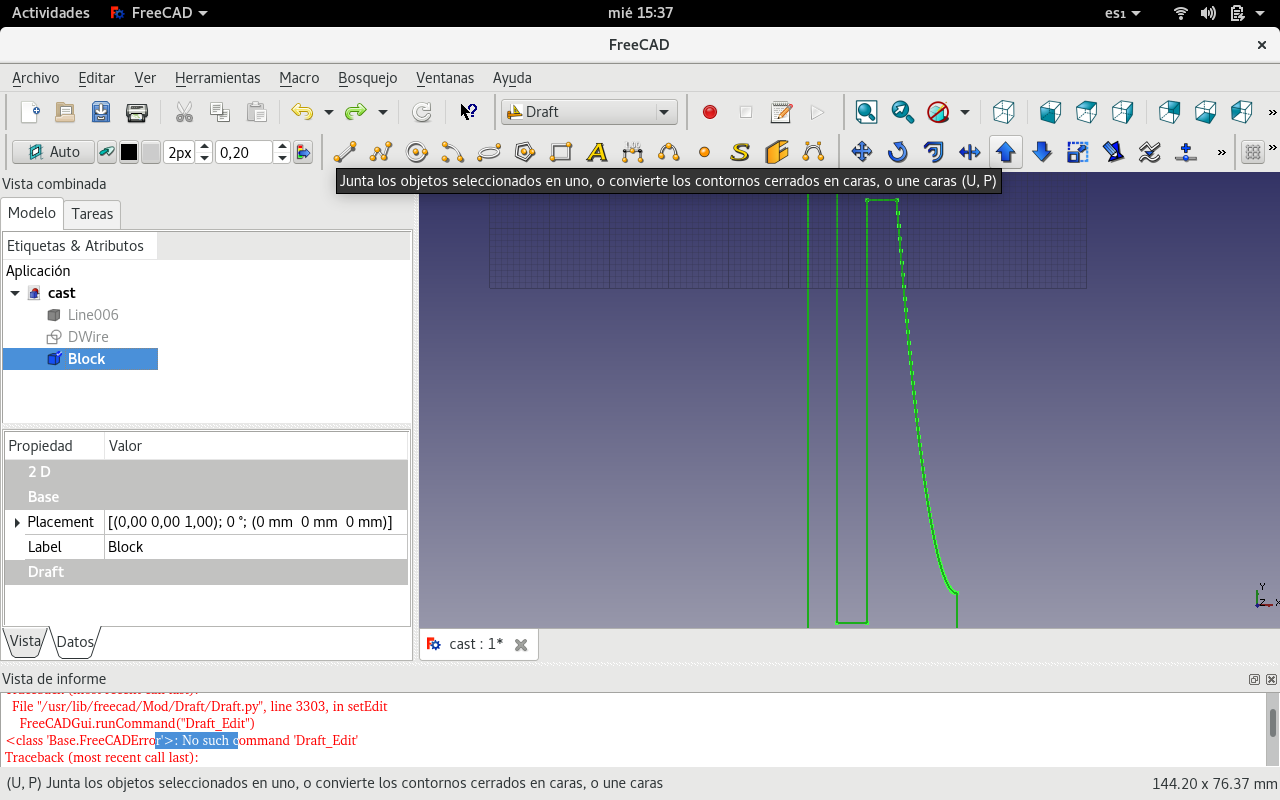
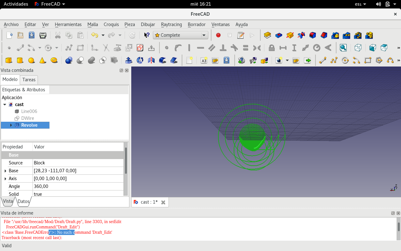
Was about to use the rotate tool. But tryed the revolve tool instead.
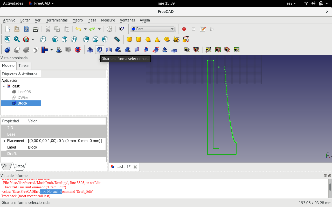
Defined the revolution axis
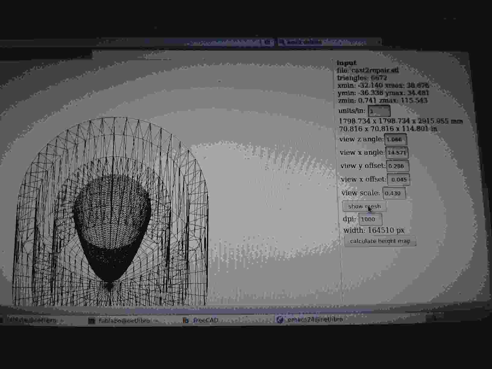
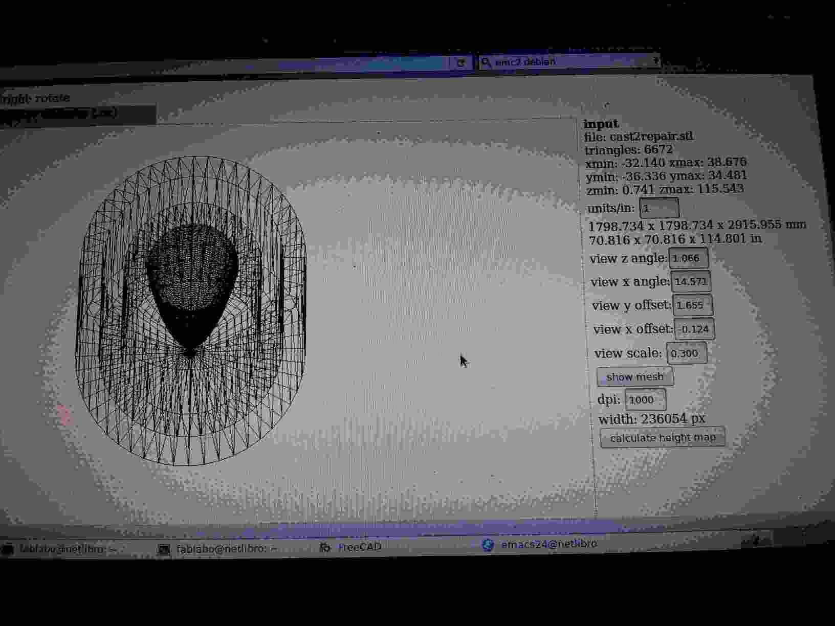
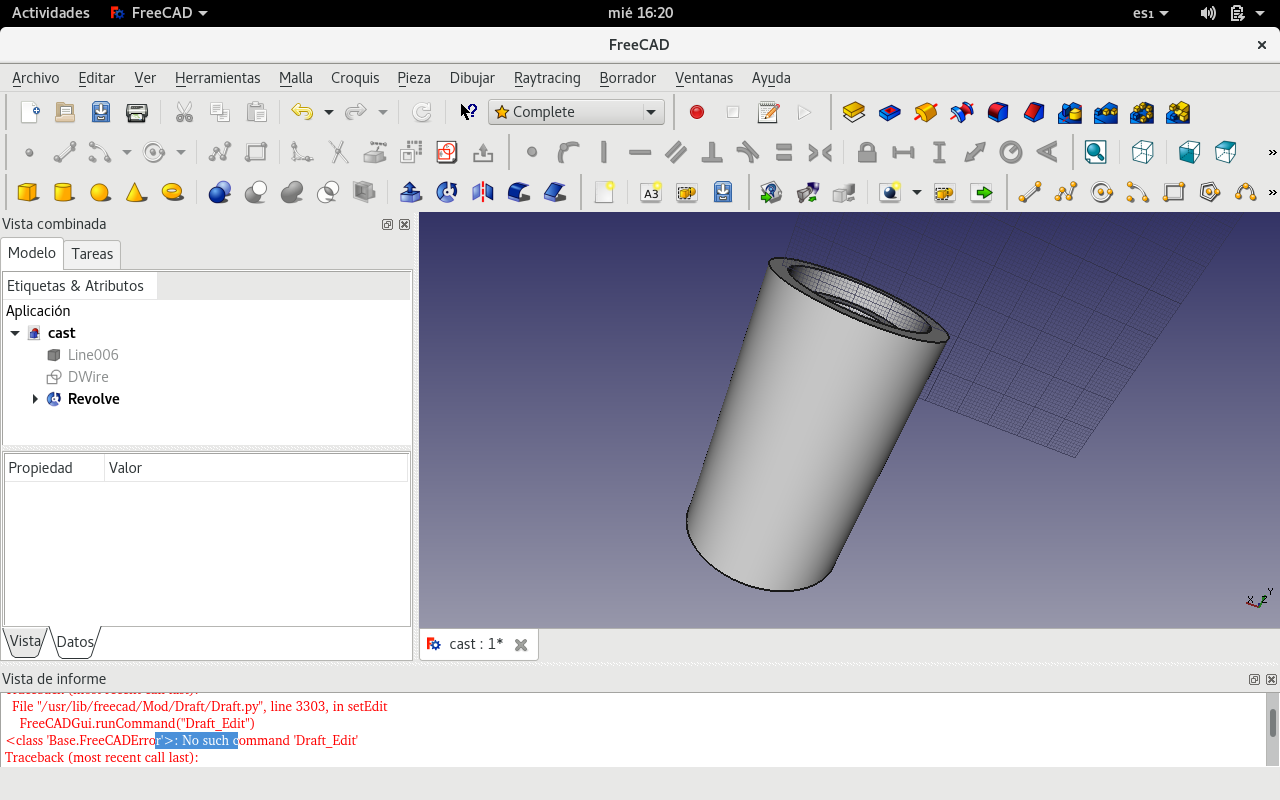
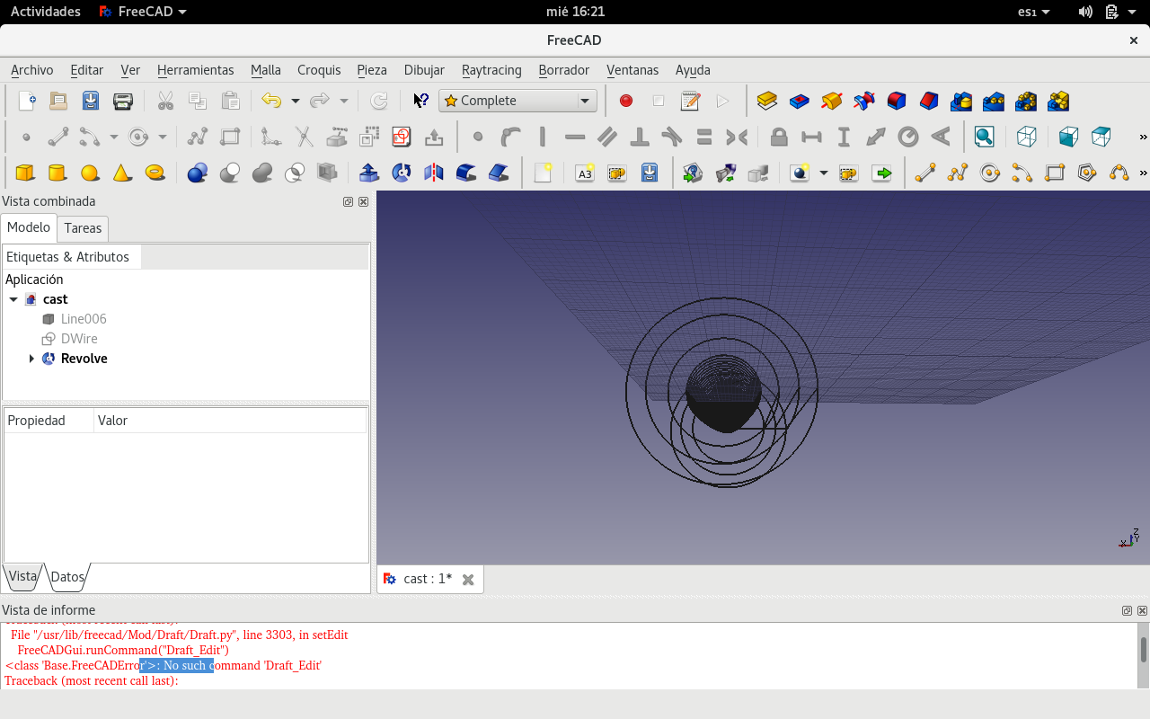
We can see different views of the resulting 3D figure for machining a piece to make a mold for the paraboloid reflector.
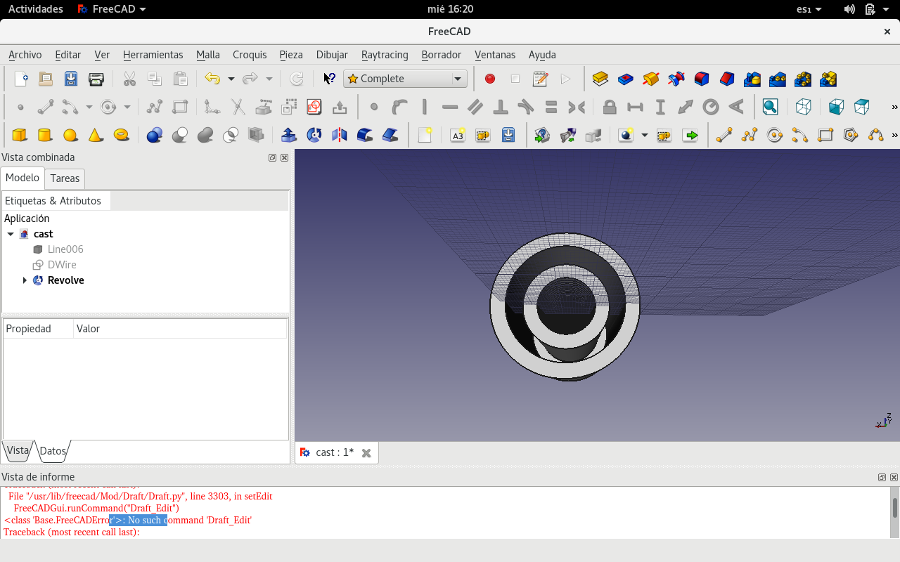
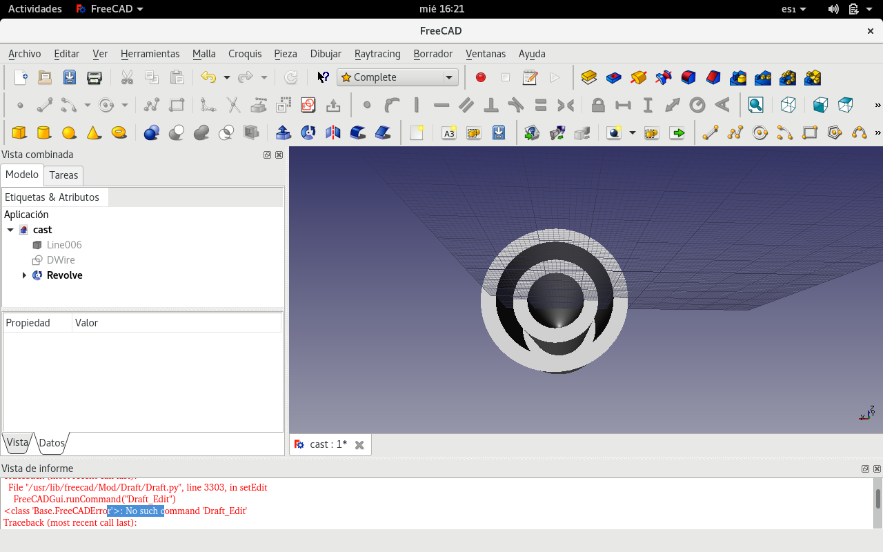
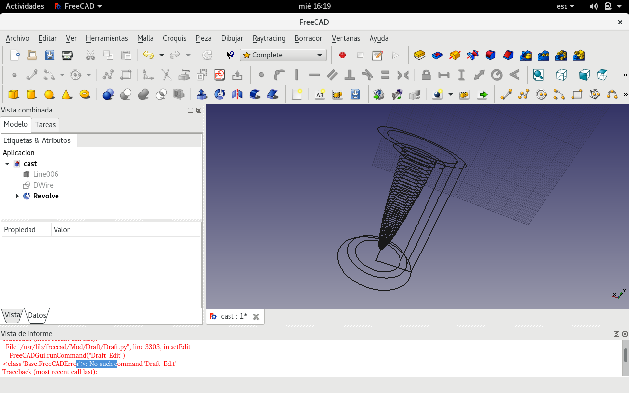
And these are views of the piece from a wire mesh perspective.
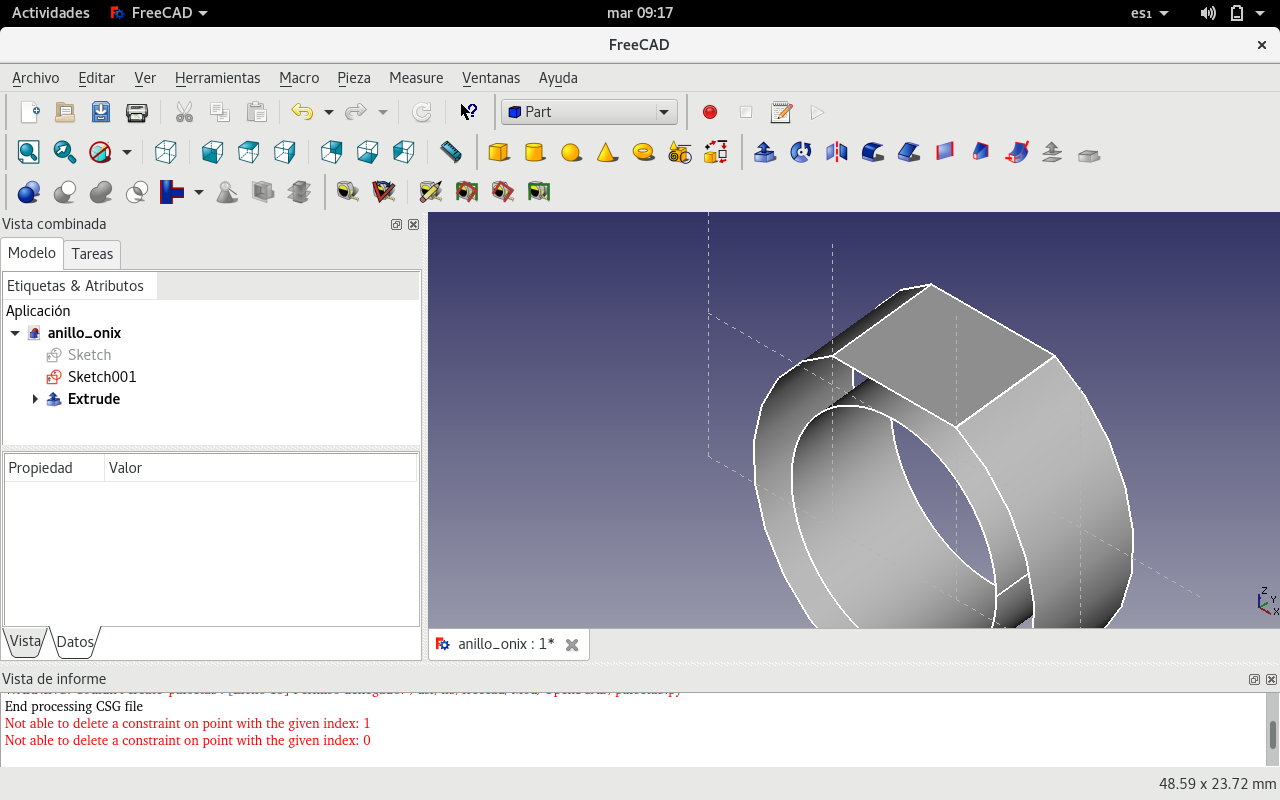
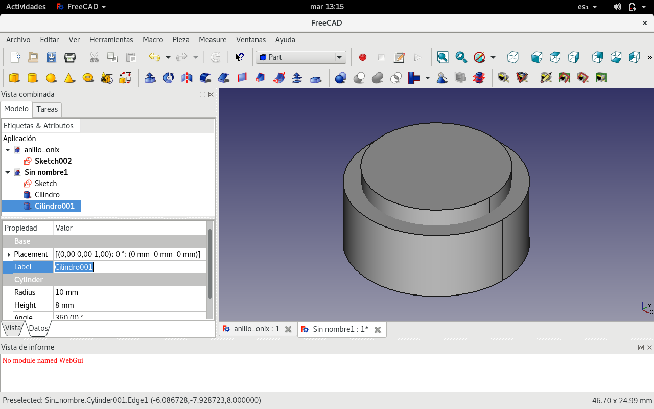
Designing a ring with FreeCAD
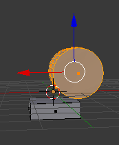
I made two cylinders with the same center but of different diameters and lengths.
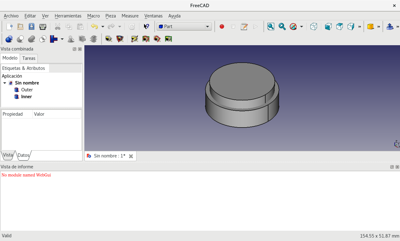
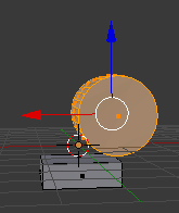
Then I made a Boolean subtractive operation. Just chose the figure that stays before the figure that subtracts. (Held the Control key when selecting the second figure.)
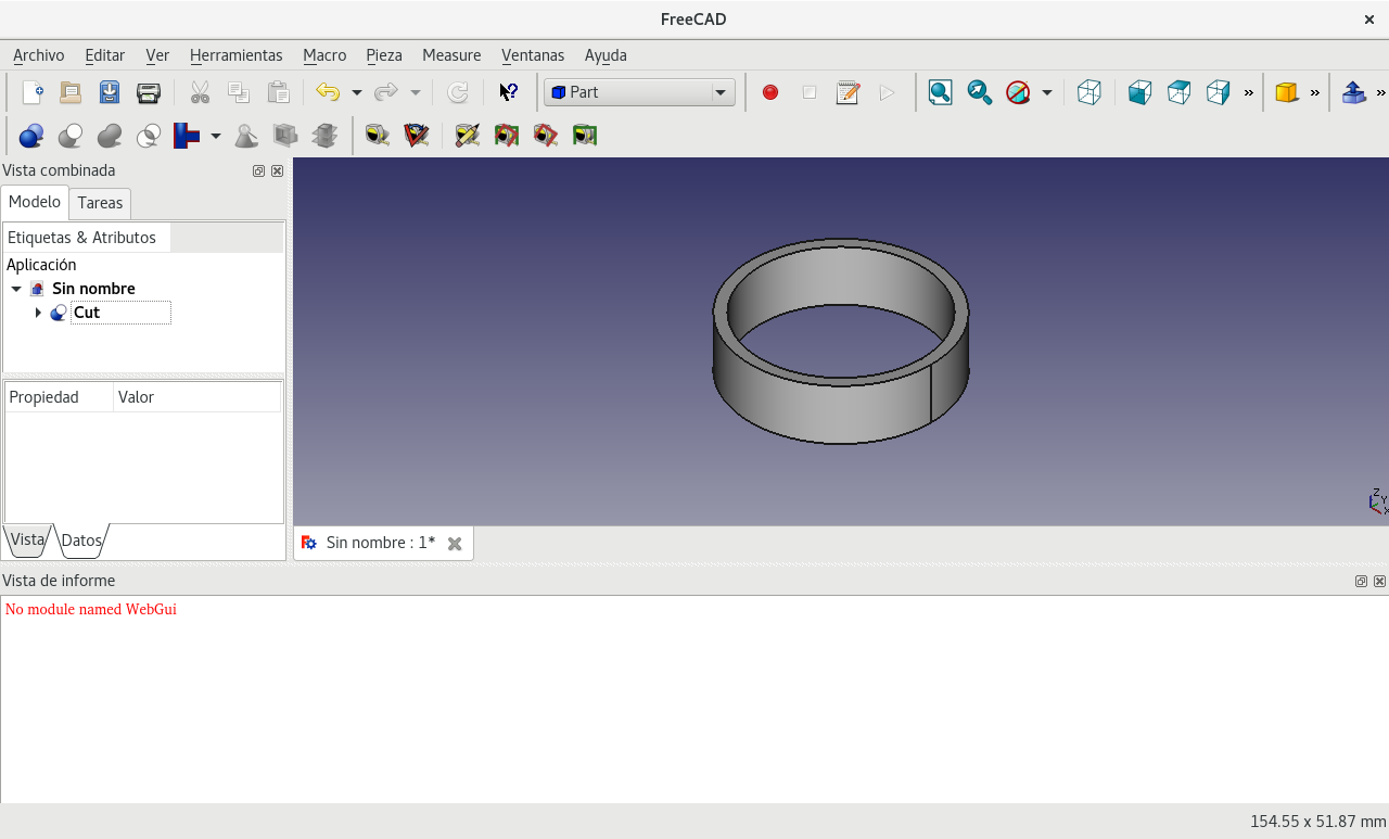
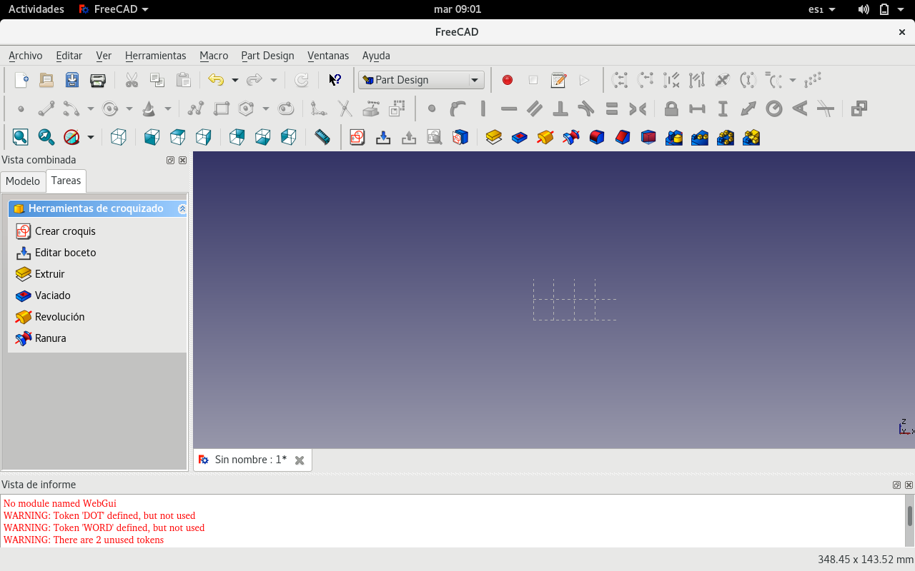
But decided to start again on the Part Design workbench.
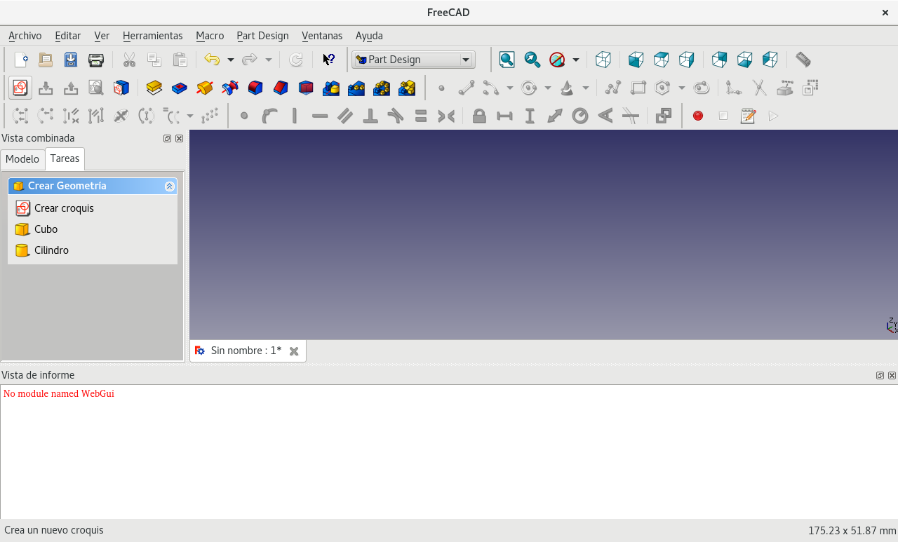
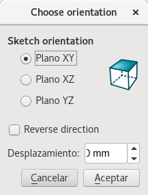
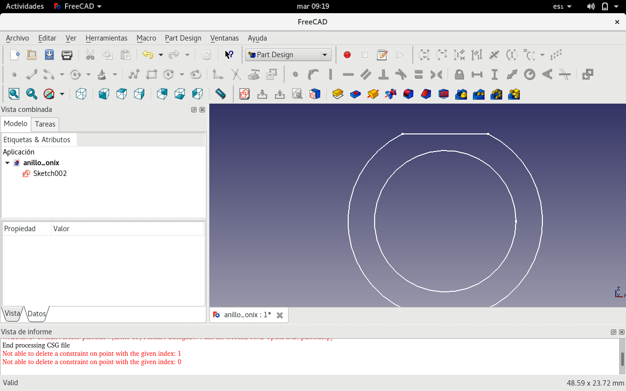
Created a sketch on XY plane.
Drew two concentric circles and a rectangle inscribe between them.
But the program closed unexpectedly. Fortunately, the software is designed to recover files.
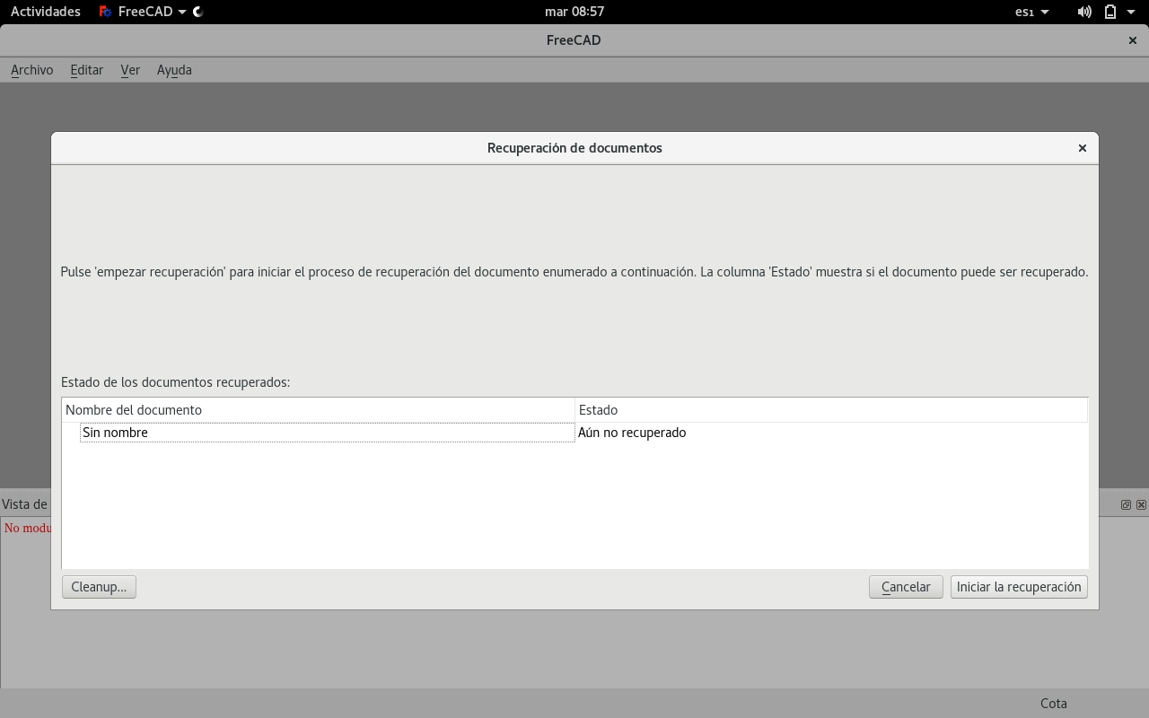
And it did so successfully.

But not with the latest data. So I had to start again.
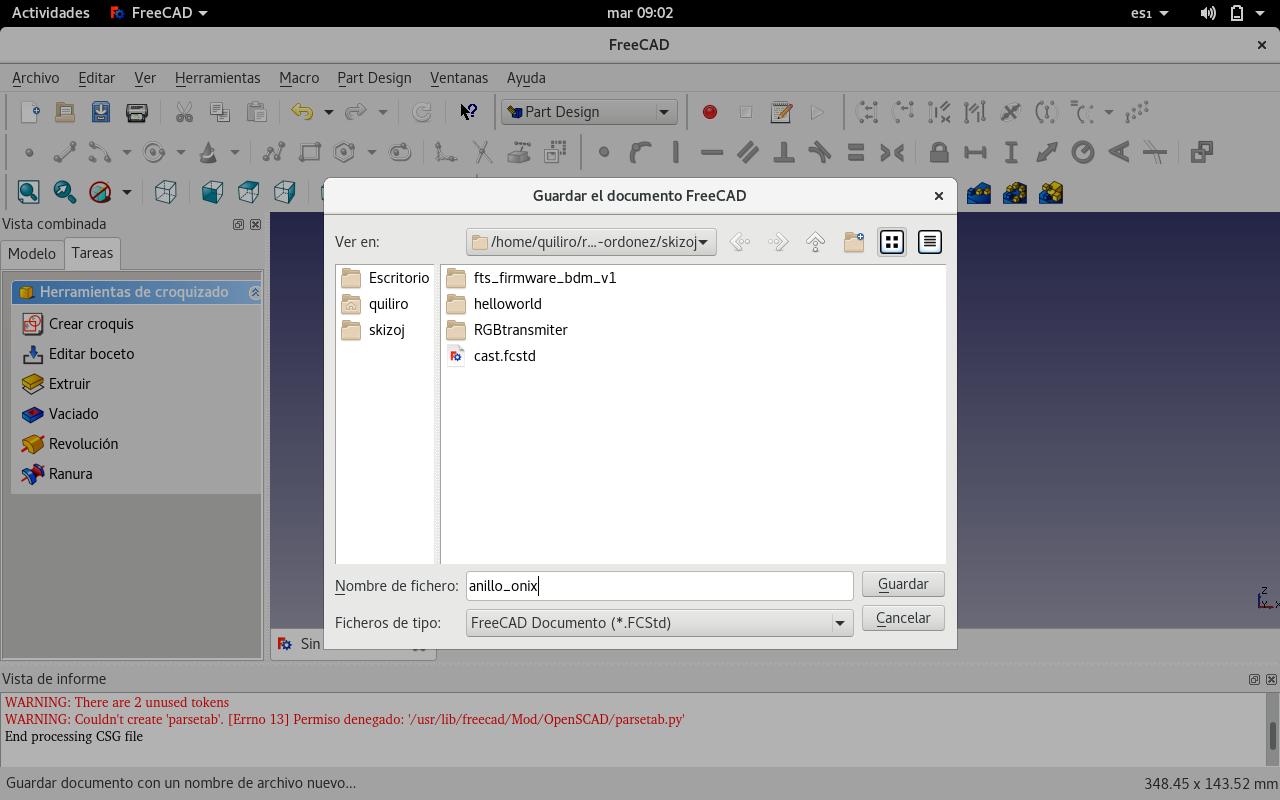
And decided to save the image soon.
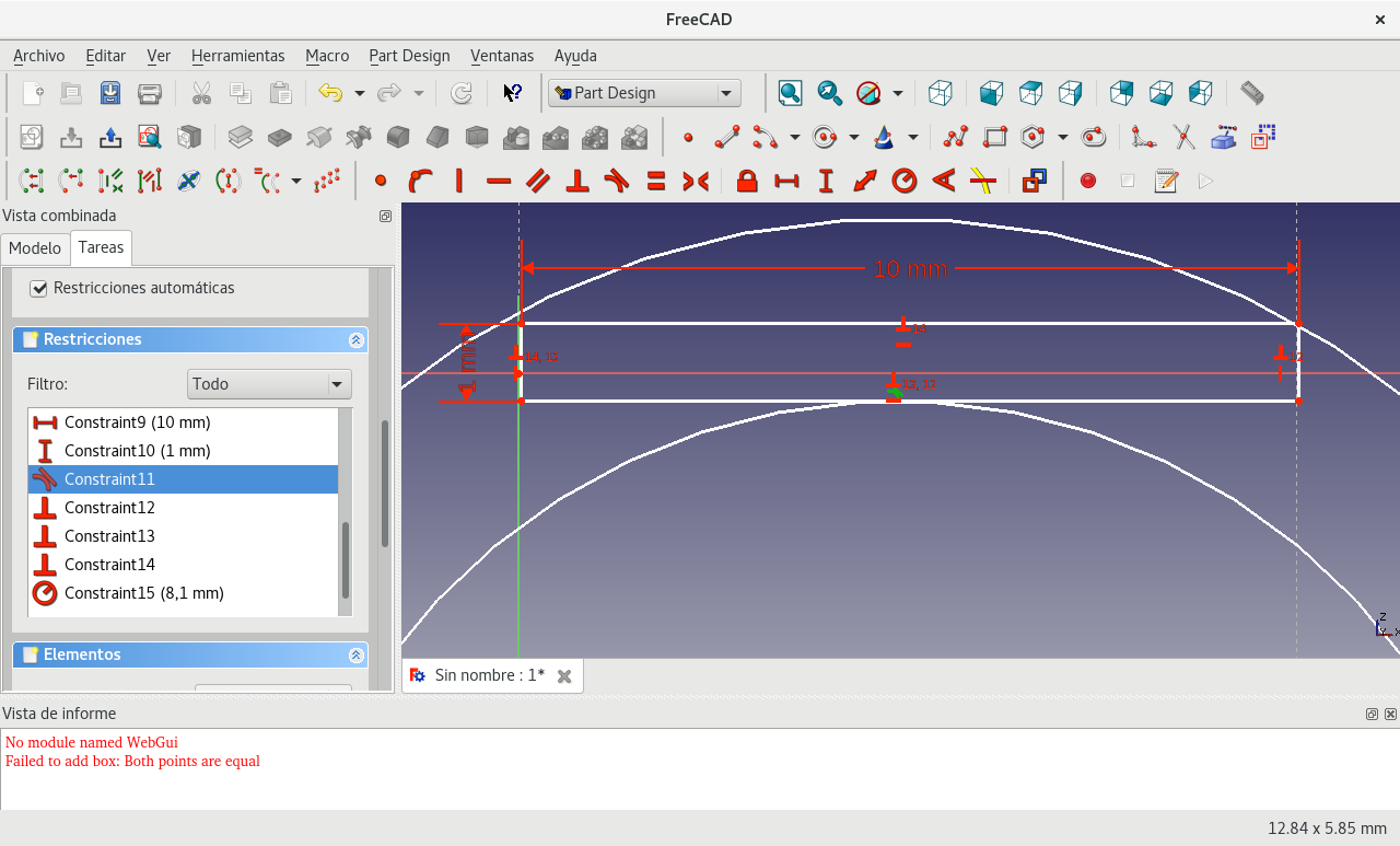
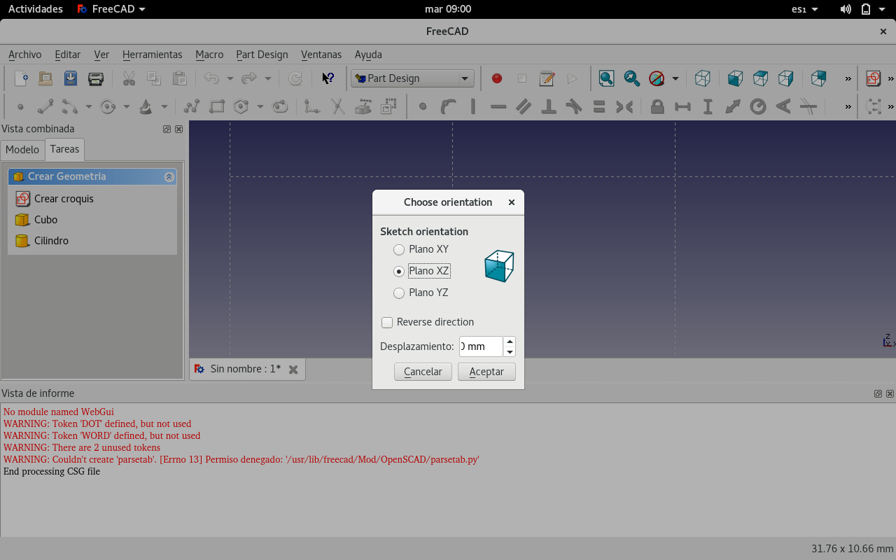
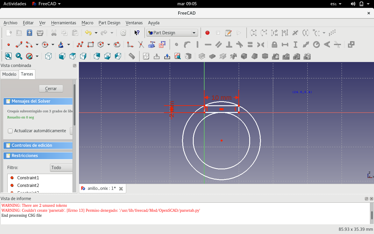
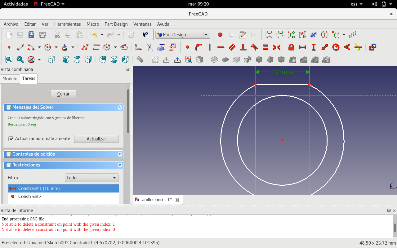
I sketched on the XZ plane this time.
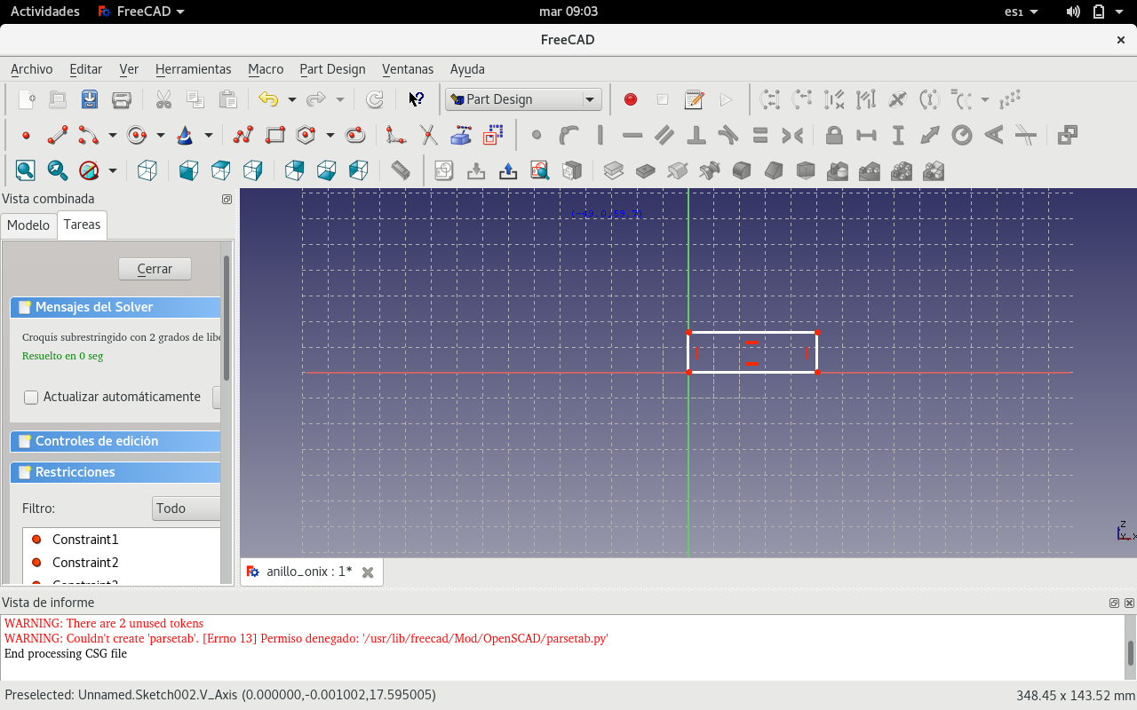
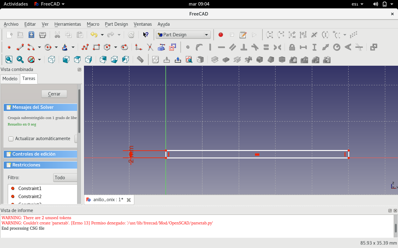
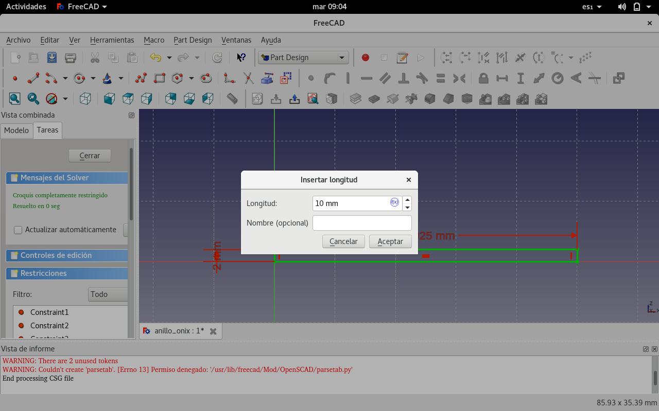
Started with a rectangle.


And inscribed it between two concentric circles again.
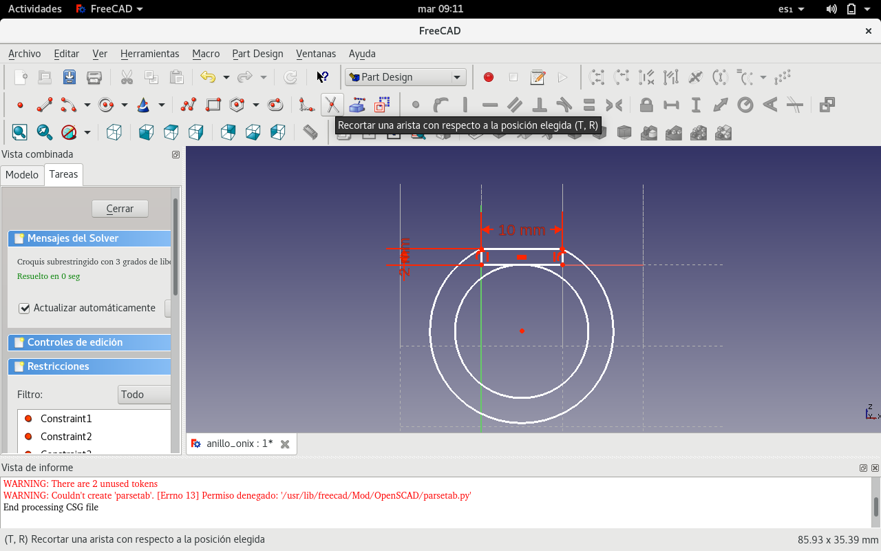
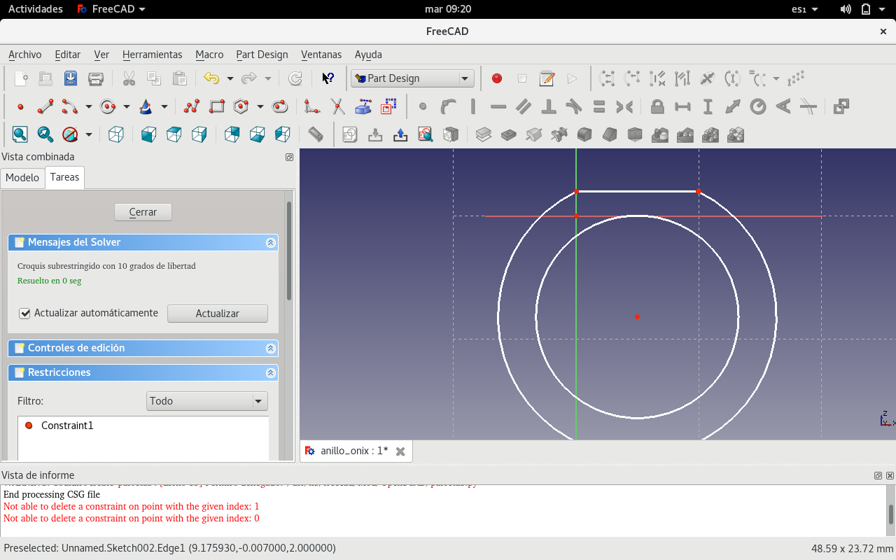
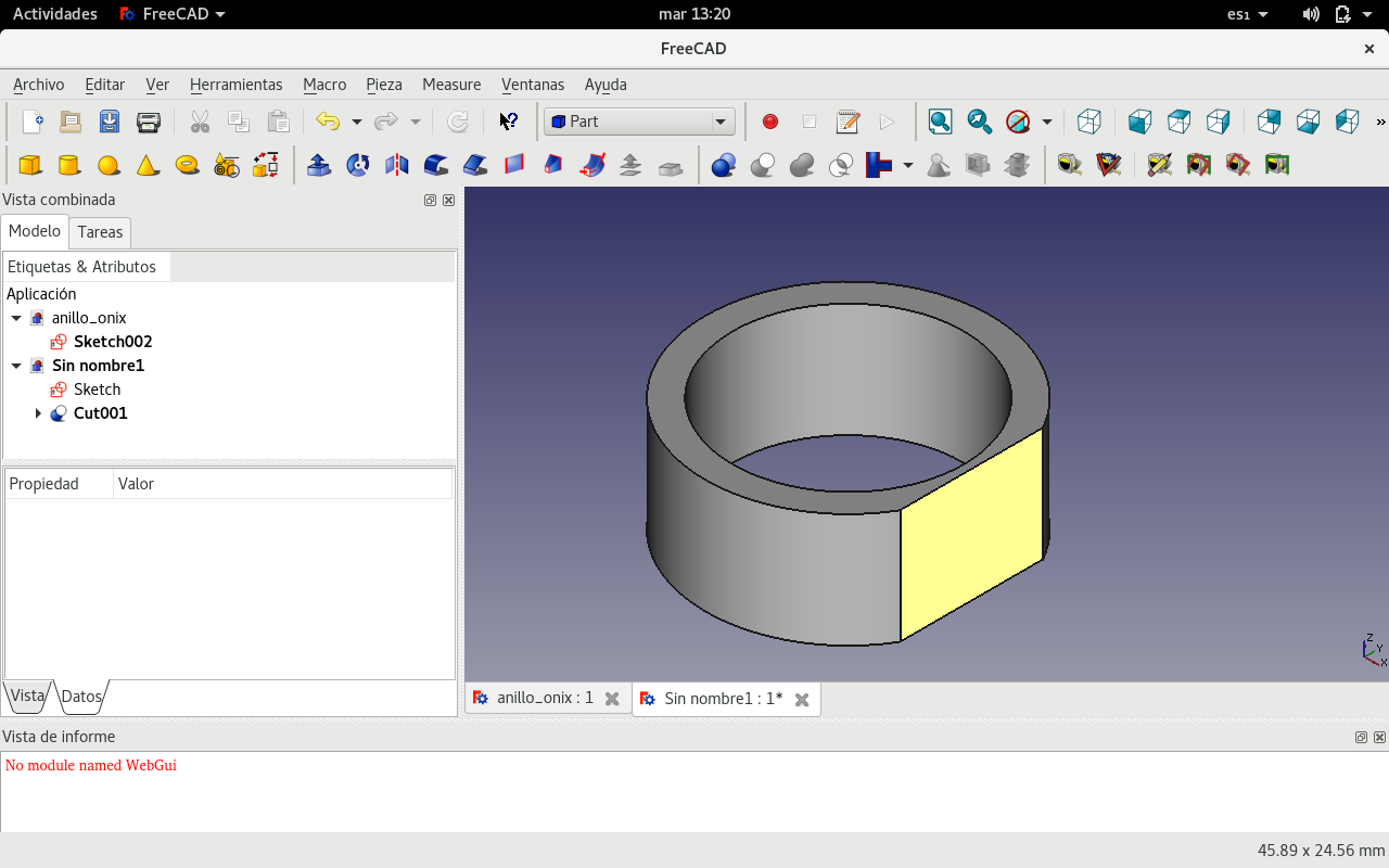
I cut the outer circle at the intersection of the rectangle.
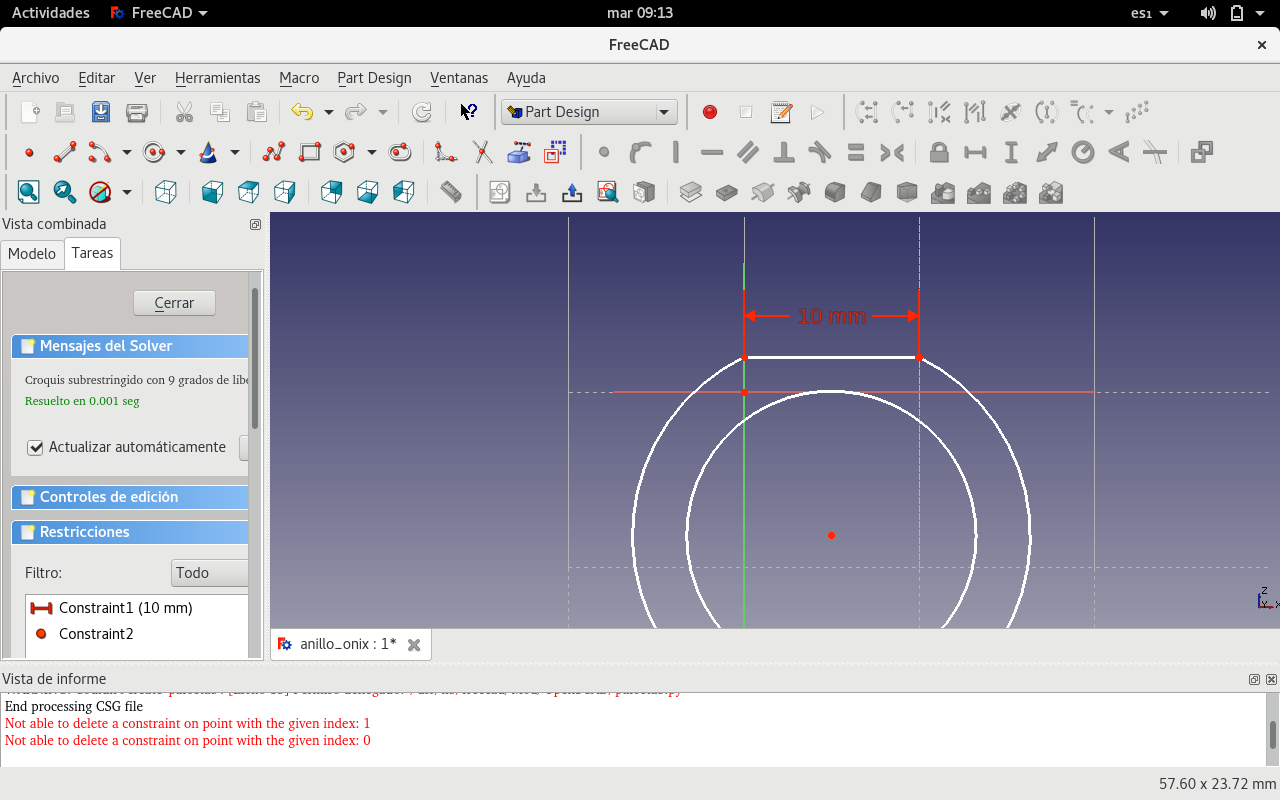
And removed the rest of the rectangle.
Selected all the elements and proceeded to extrude.
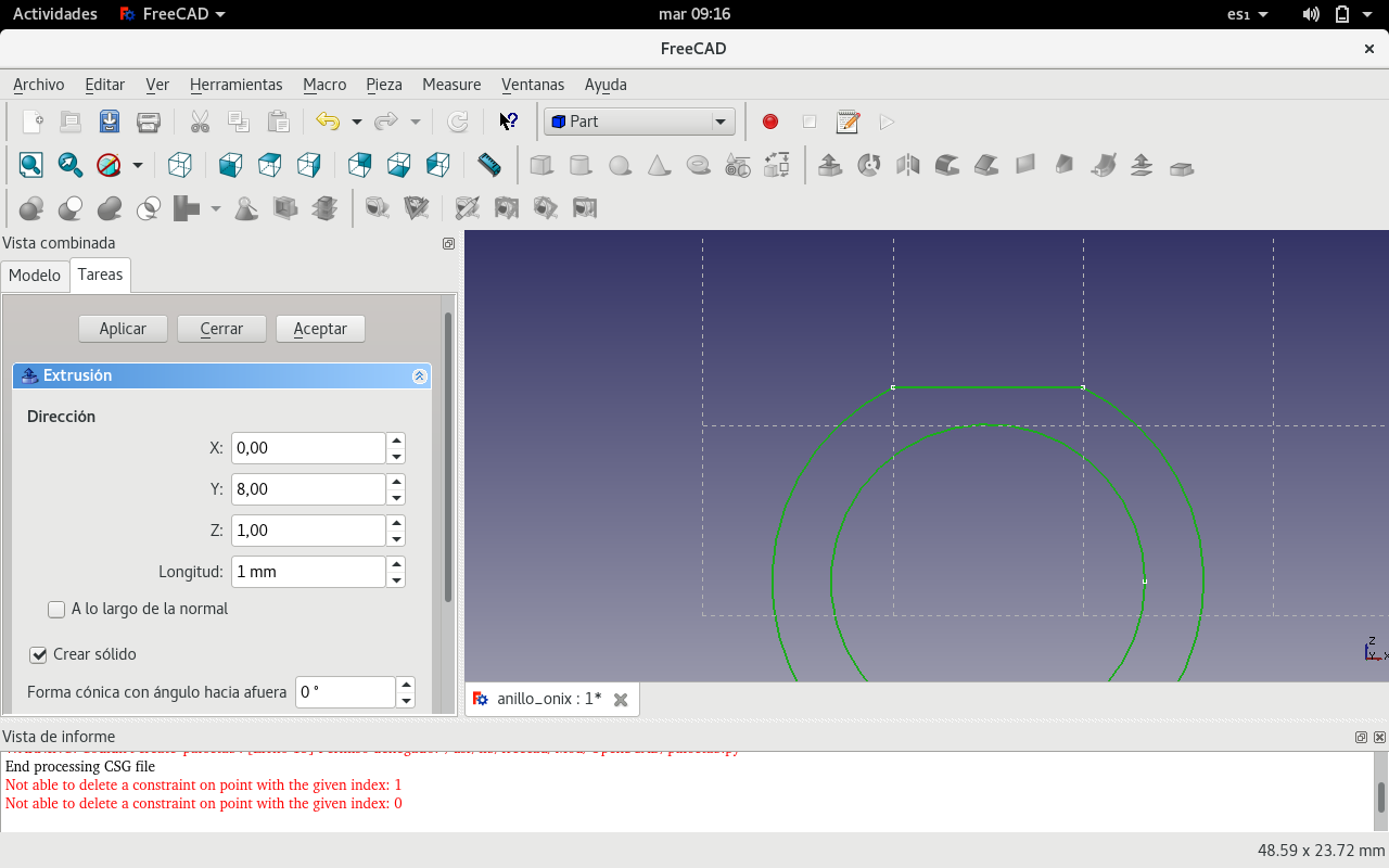
But that was not the desired result. So I went back to the starting point.
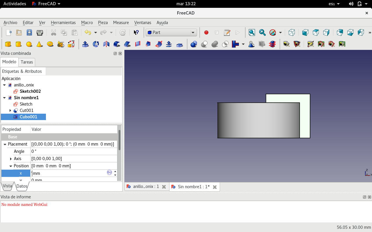
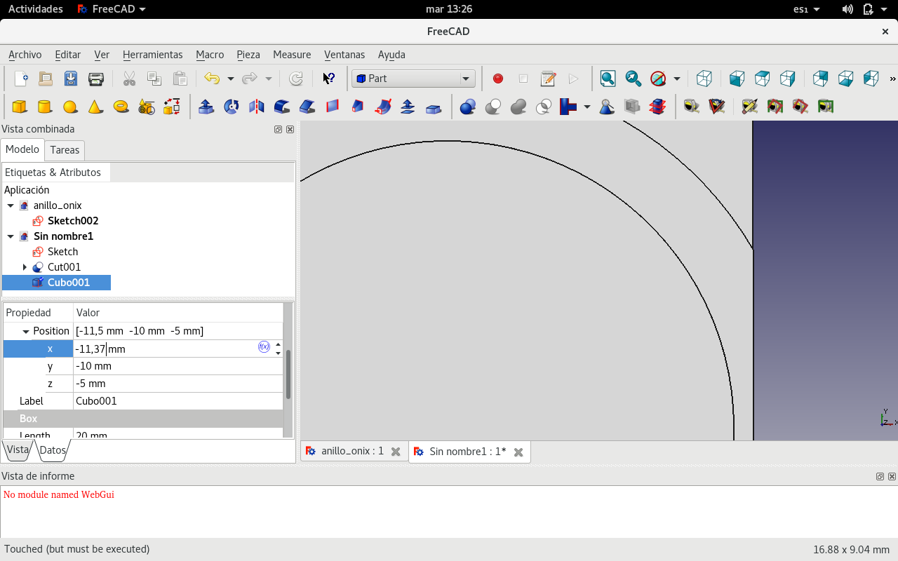
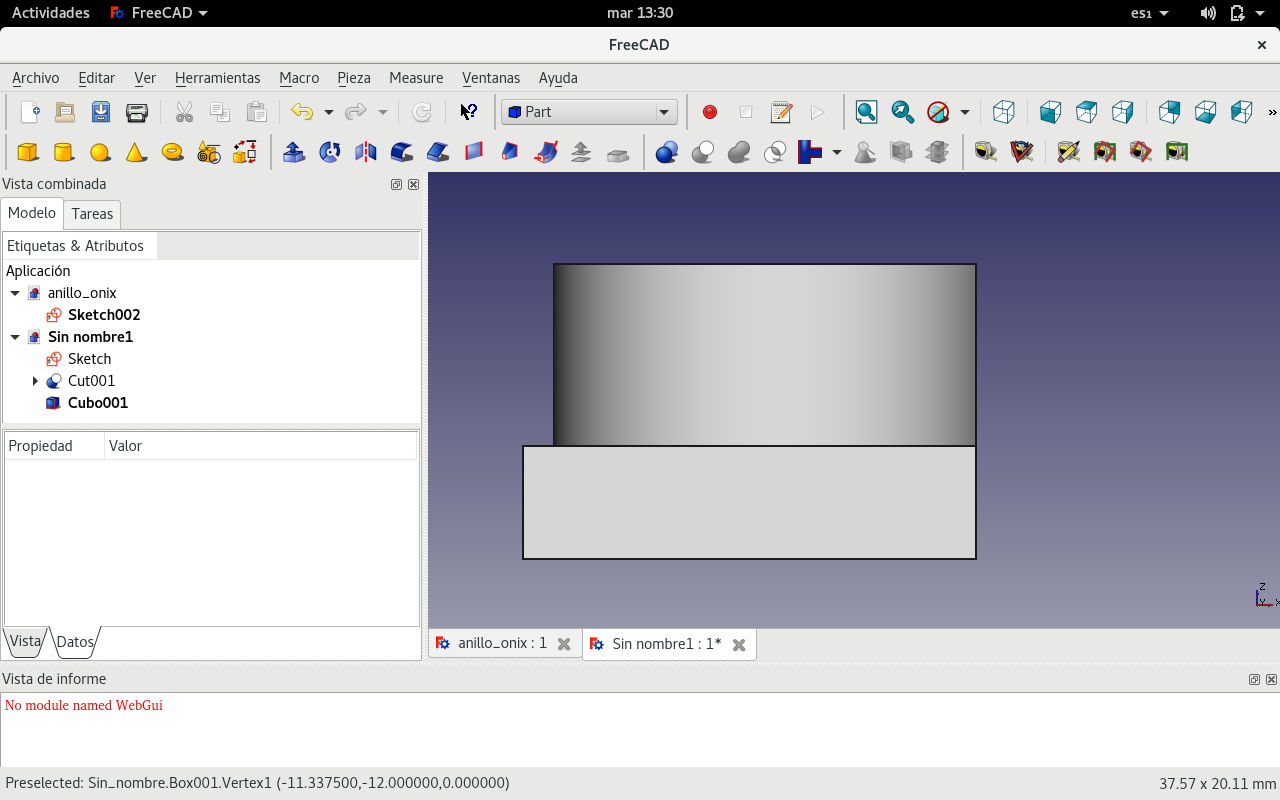
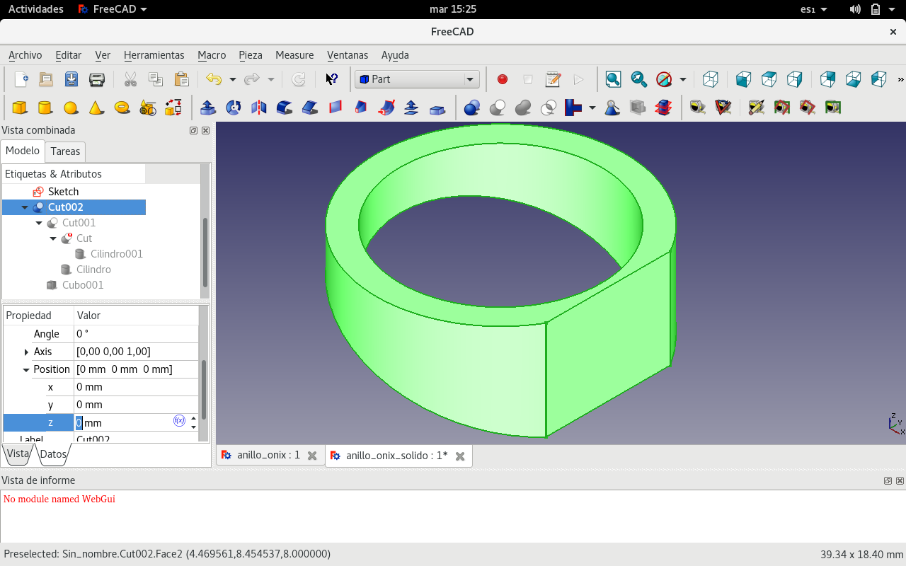
I needed to make a thin ring bottom. So I used Boolean subtraction with an angled cube to achieve it.
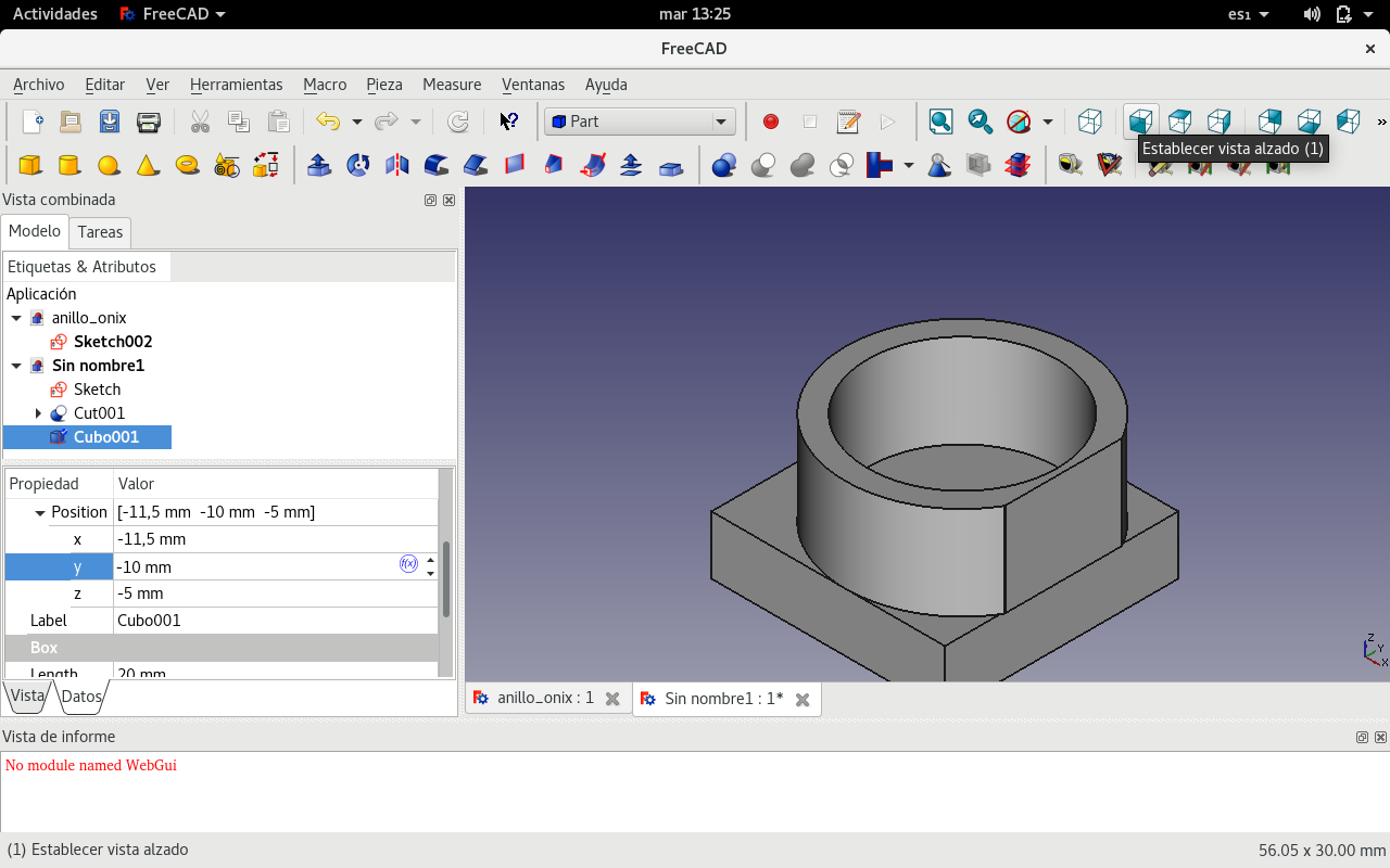
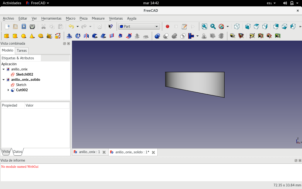
So here it is!
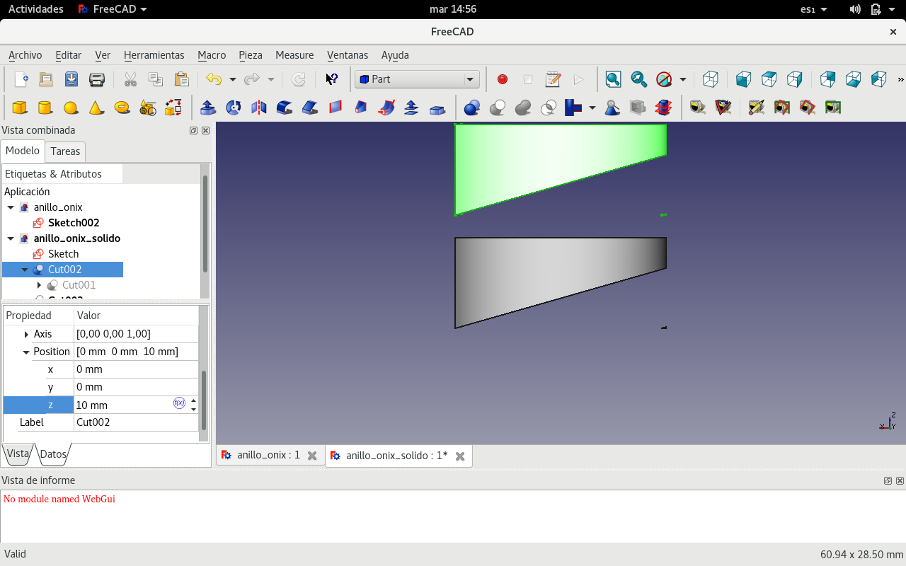
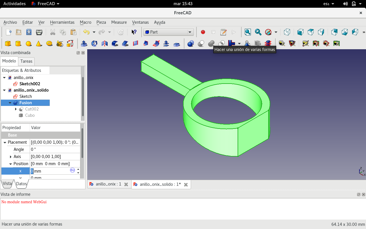
And this is it with the feeding duct for the silver to enter.
Conclusions
There are many softwares for 3D design, ranging from the most visual to the least and from the most functional to the least. Usually, as with most software, the more visual it is, the least functional. Nevertheless, the entry barrier to less visually oriented software is greater. Among software that is free (as in freedom or libre in another word), there are various alternatives for raster and vector, for 2D and 3D. But I felt the best way to choose is the less visual one because it provides more possibilities to learn more and even modify the software to suit the user's needs. Of course that, for modifying, it is necessary to learn new skills according to the modifications that are needed: from documenting, to reporting, to designing usability, all the way to programming. But learnind and applying those skills provides autonomy and freedom.
- Mods is very interesting because it can work remotely as well as locally. It is very important to be able to control the software stack. So a local installation is a plus. It is a nice framework to transform images to Gcode for milling among many other things.
- Blender can be parametric 3D vector app (which gives it an engineering edge) but it is more visual rather than command-line (which makes it heavier and less adequate for mathematical and geometrical tasks) in the non-animation perspective.
- Inkskape seems a very good GUI 2D vector app which can be extended. But I think that mastering ImageMagick can be a more valuable skill for working faster and having more power.
- GIMP is very powerful for GUI 2D raster. I would rate it as I did with Inkscape: mastering Imagemagick could prove more valuable in the long run.
- FreeCAD seems to be the most powerfull 3D vector tool. Learning Openscad which is command-line with visual representation looks good too.
3D Substractive and additive processes require closed meshes that need experience to build because structures need to be closed in order to produced with CNC additive and substractive processes. They also require developing skills to transform 2D shapes to 3D shapes.
Keystrokes help make work faster. But they require good memory. The best balance comes when the GUI shows the keybindings for the commands that are being used in that moment. That way the user learns by repetition.
Platonic and Aristotelian solids provide a way of understanding the geometric structure of solid shapes. These are useful for building geodesic domes.
Sources
You can download the paraboloid matrix 3D file made in FreeCAD.
and also the parametrized version of the paraboloid matrix 3D file.
Here is the ring source file.
Here is the source OpenSCAD parabola file.
Source file for parabola drawn in Inkscape.


