Materials, tools and software
Roland MXD - 40 (Tools)
plaque copper (Materials)
Eagle (Software)
DesignSpark (Software)
 |
 |
 |
 |
|---|
Roland MXD - 40 (Tools)
plaque copper (Materials)
Eagle (Software)
DesignSpark (Software)
First, use a program called DesignSpark, a program that you recommend in class. In the link you can know more about this program.
DesignSpark PCB is here to help your company explore more design options - leading to increased innovation. At the core of this unique software is a powerful software engine that enables you to capture schematics and design PCB boards and layouts.

This software has a great variety of processes such as mechanical design, no limitation on your schematic size, Integration with
PCB Part Library and more.
For the download this program did not ask us for any kind of payment, nothing more than that we registered creating an account. To create
a gutter you must follow the following steps:
Note: You must be connected to the internet throughout this process.
1. At the DesignSpark homepage create an account.
2. Activate this user account by clicking the verification link within the email.
3. Confirm that your account works by logging in to the DesignSpark homepage.
4. Download the DesignSpark PCB software.
5. Run the program to install on your system. You must be an Administrator to be able to do this.
6. Launch from the short cut icon to complete the process by registering the software. You will have to run the program with administrator
rights as it accesses the internet. Right click on the shortcut on your desktop and select "Run as Administrator". NOTE: This is different
from being logged in to Windows as an Administrator as it gives the program higher privileges.
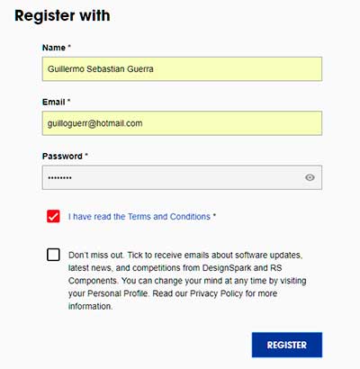
7. Complete the registration screen. Complete ALL required fields including the Job Title / Position and accept the T & C's. If clicking
the button produces no action, check ALL of the fields are complete and look for errors. Ensure you email address is valid and correct.
Incorrect entries will result in errors later on.
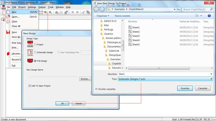
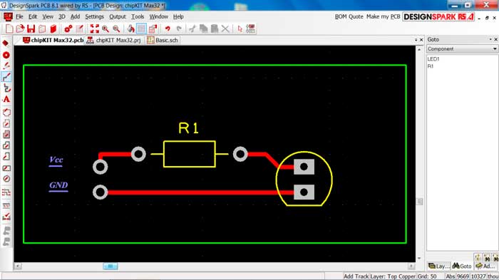
When we open we choose to create a new document by clicking on FILE and then on NEW, this gives us a window in which we choose the file type that we are going to choose and for this process we choose PCB DESIGN as the next step we choose in the place that we want to save .
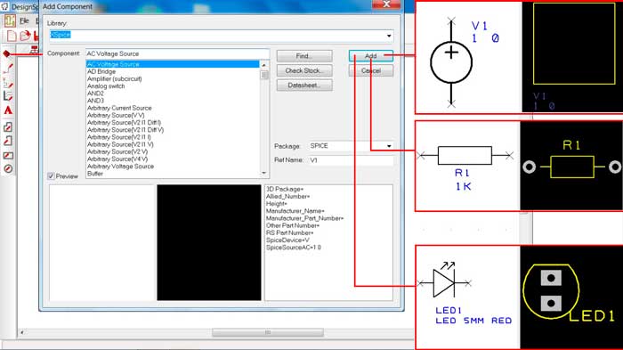
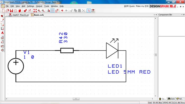
Once the above processes have been completed, it allows us to generate the schematic within which we will select the components for the PCB that we need to develop. First we add voltage source for, a led and a resistance of 330 ohm, for this we click on the button ADD COMPONENT selecting the components detailed before and with the tool ADD SCHEMATIC CONNECTION we will connect each of the components between them from the source directly to the cathode and the anode with the positive resistance of the source.
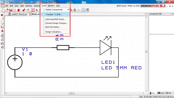
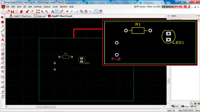
As next step we select the top bar the tool button and click on TRANSLATE TO PCB and this will take us to the graphic window with the chosen components with which we can design our board creating the communication blocks between each component.
As a first step we modify the work area with the mouse cursor by clicking and dragging until we get the measurements that we consider correct.
To join the components creating the tracks we use the tool called ADD TRACK with which we join the components following the connections of the schematic.
It is an intuitive program, easy to handle and for many reasons like its interface, its navigation tools, among others is a program similar to Eagle.
Then you can see the use of Eagle for the development of PCB, this software is used for the development of the circuit to be machined.
For the development of this assignment we will use eagle software with which we will design our electronic circuit.
As a guide, reference was made to the assassination of Carlos Moreno, who can see his work in the following link.
For the selection of the components, we analyzed the basic needs to perform the practice and the
engraving of the software for it we selected the following components:
- 1 Atini 44
- 2 resistances de 4.99 k
- 1 resistance de 0 ohm
- 1 resistance de 499 k
- 1 resonator de 20 Mhz
- 1 capacitor de 0.1 uF
- 1 led
- 2 button
- 1 header (espadin 6)
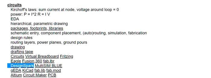
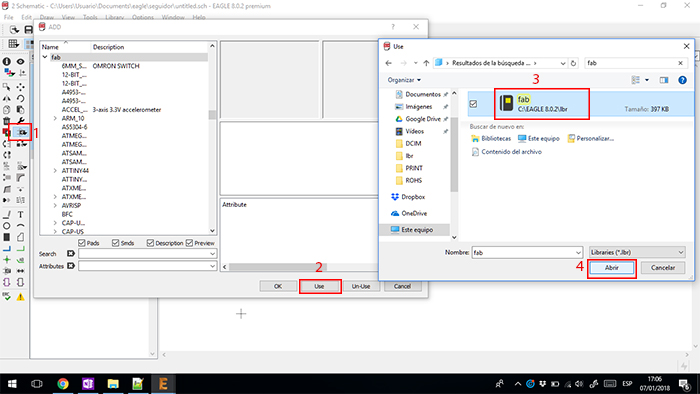
first download the "fab.lbr" file you can get it in the following link.
We save the downloaded file in the library folder of the program and open it to be able to select its components. Select the "Add" button and followed by the "Use" button and choose the library.
For this assignment, I use eagle. In this software, you can analyze the position for communication between components.
First install eagle and import the "Fab library" in this library you can see all electronics components for the fab academy course.
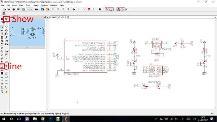
To generate the plate open Eagle and choose a new project and choose the components mentioned above.
The connection made thinking of a way to record the same microcontroller and in turn for the project to fulfill its function.
once chosen the components to use we select the "Line" tool with which we will connect the different components and with the "Show"
tool we check that the lines are connected between the components.
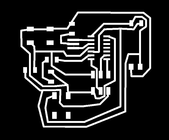
Third, Generate routing. Do you check the correct position and way of the traces for the components.
To organize the components we create a board in which we mobilize the elements looking for the appropriate
layout in which we select the best routes to generate communication paths on the board.
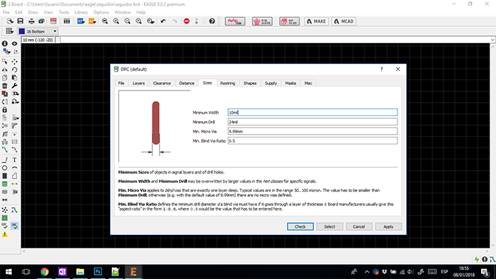
The next step is to check that the width of the track is adequate.
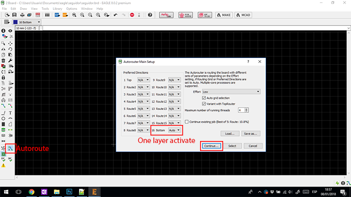
Then we chose the "Autorouter" tool and check that everything is in a single layer we can go to the next step in which the program give
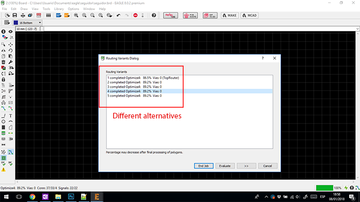
us alternatives we chose one of them and we improved it to eliminate the lines that we have to change and create another line.
Next we can see the different routes that the software gives us.
We select the option that helps us the most and we correct some clues that we can draw a better route and in this way it helps us a lot to be able to optimize the process. To achieve this step we select and eliminate the clues that we can improve your route and with the ROUTE tool we draw the tracks again.
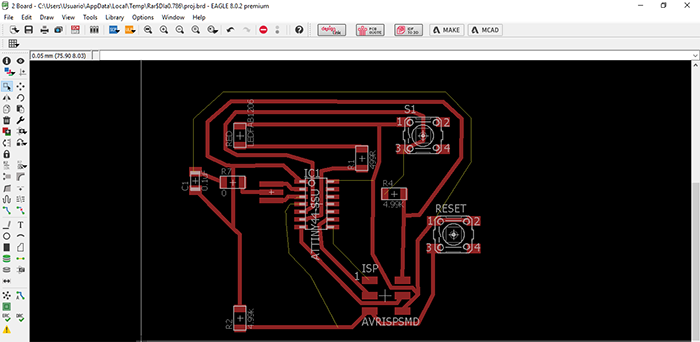
And finally you can see the finished process to move to mechanize the file.
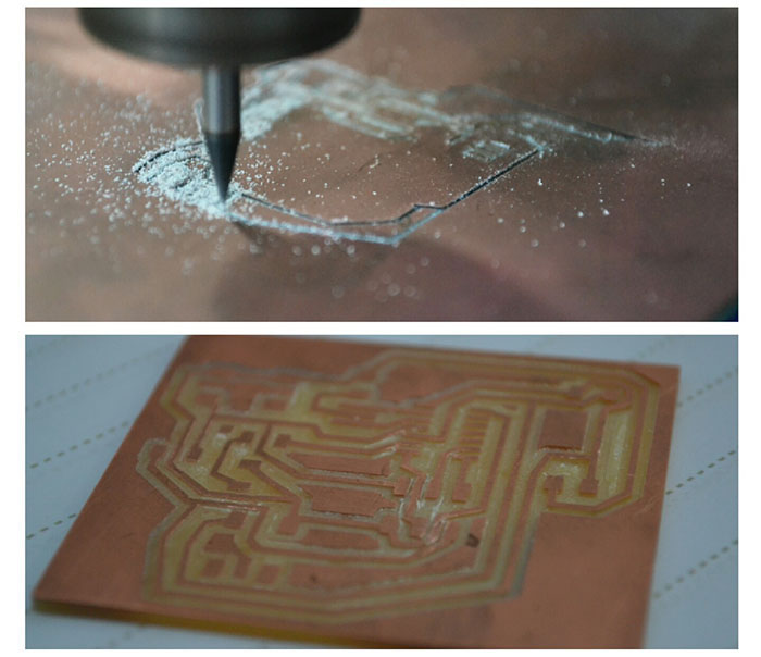
For end this assignment, we use the combination with assignment of "Electronic Production".
Use the roland machine for make de the board.
If you like to learn a little more about this process you can follow the link to go to the website of the week of electronic production
and learn more about this process.
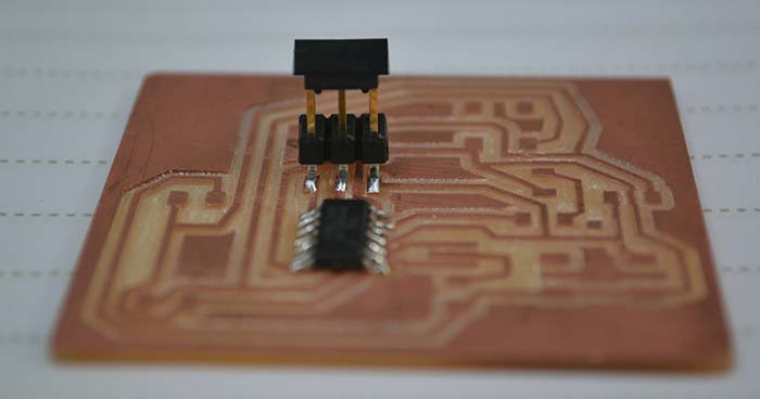
For this plate try another form of soldering of the components was placed each of the components and one by one is added tin so that this one to the component and the plate.
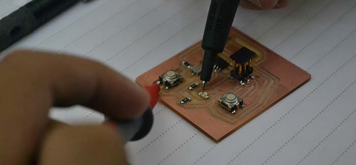
Once the previous process is finished we check continuity of the tracks and that they are not connected with others that should not be.
in the week of "Embedded programming" you will find the programming and a video with the board in operation.
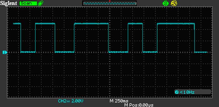
With the oscilloscope we will check the measurement of current flow for this we connect the plate to the struts of the oscilloscope and in the breadboard we connect the plate to be able to supply with a 5v source.

In this way we can see in the following image how it is in 0 and when we turn on the source it changes the oscilloscope reading the scale of the oscilloscope is 2 volts per frame.
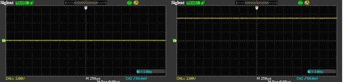
We can also analyze, based on the pulse, the changes that this generates with the passage of current since when we press we can observe how the time that is held down the reading rises and when the button is released it returns to 0.